Pro-Peak Sigma EQ Hyper User manual

Please read this entire operating manual completely and carefully, as it
contains a wide variety of specific programming and safety information.
The selection of the correct operating parameters is the responsibility of
the user. Keep this manual in a safe place, and be sure to pass it on to
the new owner if you ever sell your Sigma EQ Hyper.
Operating Manual
Intelligent Balance Charger Microprocessor controlled
high-performance rapid charger/discharger with integrated balancer
USB PC link and temperature sensor. Charge current up to 10A,
discharge current up to 5A, 1-6 series of Li-ion/Li-Fe, 1-18 cells of NiCd/
NiMH, 2 to 24V of Lead-acid (Pb)

- 2 - - 3 -
Introduction
Thank you for purchasing this Sigma EQ Hyper Charger by Pro-Peak.
This charger provides you with a rapid charger/ discharger plus an integrated balancing
circuit. It is computerised with a high performance microprocessor and specialised
operating software. It can maintain your battery at its best condition and control it safely.
Please read this operating manual completely as it contains a wide variety of specific
programming and safety information.
You need to keep this manual in a safe place, and be sure to pass it on to the new
owner if you ever dispose of the Sigma EQ Hyper.
Special Features
Operating Software
Every operating program in the unit is controlled with mutual links and communications
to prevent any possible error. It introduces maximum safety, including input voltage
warning, reverse polarity protection and a Lithium cell-count input error warning.
High-Power and High-Performance Circuit
The Sigma EQ Hyper ensures the circuit has maximum output power of 200Watts. As
a result it can charge or discharge up to 18 cells of NICd /NiMH and 6 series of Lithium
batteries with maximum current of 10A. Furthermore, the cooling system works with
extreme high efficiency and can run this high power without effecting the circuit or
operating system.
Individual Cell Voltage Balancer for Lithium Batteries
The Sigma EQ Hyper has an individual cell voltage balancer inside. It does not need a
separate balancer when charging Lithium batteries (Li-ion/ Li-Po/ Li-Fe).
Balance Individual Cells on Discharge
The Sigma EQ Hyper can also monitor and balance individual cells in a Lithium battery
pack during the discharge process. If the voltage of any one cell varies abnormally, the
process will be stopped with an error message.
Various Types of Lithium Battery
The Sigma EQ Hyper can accept three types of Lithium battery-Li-ion, Li-Po and
Li-Fe. Each has different characteristics due to their chemistry. Any one of these can
be selected before the job is processed. For their specifications, please refer to the
‘Warnings and Safety notes’ section.

- 2 - - 3 -
Lithium Battery ‘Fast’ and ‘Storage’ Modes
A Lithium battery can be charged for special purposes. The ‘Fast’ charge reduces the
charging time of a Lithium battery and ‘storage’ mode controls the final voltage of the
battery to suit storage for long periods of time.
Maximum Safety
Delta-peak sensitivity: The automatic charge termination program works on the principle
of the Delta-peak voltage detection.
Data Store/Load
The data store/load can store a maximum of 10 different pre-set battery regimes. The
data can be established within the program settings of the charger. This data can be
found at any time and the process can be executed without program settings needing
to be made.
Cyclic Charging/Discharge
Performs 1-5 cycles of charge>discharge or discharge>charge continually for battery
refreshing and balancing.
PC Based Analysis using USB Communication (*)
For the more advanced user, the Sigma EQ Hyper offers a PC based program that
can analyse the characteristics of the battery via the USB port. It can produce a graph
of voltage, current, capacity and temperature curves. It can also show the individual
voltage of each cell in a Lithium battery pack.
Special Features (Continued)
(NiCd/NiMH) Auto-Charge Current Limit
Capacity Limit
When charging NiCd or NiMH in ‘AUTO’ current mode, you can set the upper limit of the
charge current to avoid feeding too high a current to the battery. This is very useful when
charging low impedance and small capacity NIMH batteries in ‘AUTO’ mode.
The charging capacity is always calculated by multiplying the charging current and total
amount of time. If the charging capacity exceeds the limit the process will be terminated
automatically when you set the maximum value.
*Separately purchased program kit (CD plus USB link cable).

- 4 - - 5 -
Input Power Monitor
In order to protect the source DC battery from damage, the input voltage must be
continuously monitored. If the voltage drops below the lower limit the process will be
stopped automatically.
Automatic Cooling Fan
The electric cooling fan comes into action automatically only when the internal
temperature of the charger is raised.
The temperature of the battery whilst charging will rise due to its internal chemical
reaction. If the temperature limit is set, the process will terminate when the limit has
been reached.
Temperature Limit (**)
Processing Time Limit
You can also set the maximum processing time to prevent damage from any possible
defects not otherwise detected.
DC Output Sockets (14V)
There are two 4mm sockets on the left side of the charger that can supply a 14V DC
power source for other chargers when using the AC input source (only). It is rare to use
all of the 200W power supply output and this feature allows you to power smaller DC
chargers at the same time.

- 4 - - 5 -
DEC. INC.
Batt. Type Start
LiIon/LiPo/LiFe: 1-6 cells NiCd/NiMH: 1-18 cells Pb: 2-24V
Charge Range: 0.1-10A Discharge Range: 0.1-5.0A
Circuit Power: Max.Charging 200W / Discharging 25W
BALANCE
CHARGER
DISCHARGER
DUAL
POWER
AC Input 180V-240V
Output charge lead
4mm banana
female
Individual cell
balance ports
LCD Screen
16 Characters, 2 lines
DC Input 11V-18V
(T-Plug Socket)
Temperature
Sensor
Batt type/Stop
To select main program
To stop the operation
Dec/Inc
To select sub program
To alter the value
Start/Enter
To resume or start the
operation
USB Port
Charger Overview
• Never leave the charger unsupervised when it is connected to its power supply.
If any malfunction occurs the process must be terminated immediately.
• Keep the unit away from dust, damp, rain, heat, direct sun light and vibration.
• Do not drop the unit.
• This unit and the battery, to charge or discharge, should be set up on a heat-
resistant, non-flammable and non-conductive surface. Never place them on a car
seat, carpet or similar. Keep all flammable and volatile materials well away from
the operating area.
• Please note: It is very important that the information provided is read thoroughly
and accurately before program setup is begun. If the program is set up
incorrectly, the battery can be severely damaged. If a Lithium battery is over
charged, combustion or explosion may occur!!
Warnings and Safety Notes
4mm DC Output
Power Sockets
from Internal Power
Supply (14V)

- 6 - - 7 -
NiCd/NiMH
Voltage level: 1.2V/cell
Permitted fast charge current: 1C~2C depends on the performance of cell discharge
voltage cut off level: 0.85V/cell (NiCd), 1.0V/cell (NiMH)
Li-ion
Voltage level: 3.6V/cell
Max. charge voltage: 4.1V/cell
Permitted fast charge current: 1C or less
Min. discharge voltage cut off level: 2.5V/cell or higher
Li-Po
Voltage level: 3.7V/cell
Max. Charge voltage: 4.2V/cell
Permitted fast charge current: 1C to 3C depending on the battery manufacturer’s
specification. 1C is recommended.
Discharge voltage cut off level: 3.0V/cell or higher
Li-Fe
Voltage level: 3.3V/cell
Max. Charge voltage: 3.6V/cell
Permitted fast charge current: 4C or less (e.g.A123M1)
Discharge voltage cut off level: 2.0V/cell or higher
Pb
Voltage level: 2.0V/cell
(Lead-acid) Max. Charge voltage: 2.46V/cell
Permitted fast charge current: 0.4C or less
Discharge voltage cut off level: 1.75V/cell or higher
Warnings and Safety Notes

- 6 - - 7 -
• To prevent an accidental short circuit, always connect the charger cable to the unit
first and only then to the battery to be charged or discharged.
• Reverse the sequence when disconnecting.
• Do not connect more than one battery pack to the charge lead at any
one time.
• Do not attempt to charge or discharge the following types of battery:
• Please ensure that the following points are checked before charge operation.
Warnings and Safety Notes
• Battery packs which are made up of different types of cell (including
different manufacturers).
• Any battery which is already fully charged or just slightly discharged.
• Non-rechargeable batteries (combustion hazard).
• Batteries that require a different charge technique from NiCd, NiMH, Li-ion,
Li-Po, Li-Fe or Pb.
• Any faulty or damaged batteries.
• Any battery fitted with an integral charge circuit or a protection circuit.
• Batteries installed into a device or which are electrically linked to other
components.
• Batteries that are not expressly stated by the manufacturer to be suitable
for the currents the charger delivers during the charge process.
• Has the appropriate program been selected for the battery type?
• Has an adequate current been set up for charging and discharging?
• Lithium battery pack can be composed with parallel and series circuits
mixed. Has the composition been checked before charging?
• Are all connections firm and safe? Is there an intermittent contact at any
point in the circuit?

- 8 - - 9 -
Charging
A specific quantity of electrical energy is fed into the battery during the charge process.
The charge quantity is calculated by multiplying the charge time. The maximum
permissible charge current varies according to the battery type or its performance,
and can be found in the information provided by the battery manufacturer. It is only
permitted to charge batteries at rates higher than the standard charge current if they
are stated to be capable of quick-charge.
Connect the battery to be charged to an output terminal of the charger using a suitable
charge lead. A red lead is positive (+) and black is negative (-). The charge cannot detect
the difference between the internal resistance of the battery pack, cable resistance and
connector transfer resistance. The first requirement, in order for the charger to work
correctly, is for the charge lead to be connected to an adequate conductor cross-
section. High-quality connectors (normally gold-contact type) must be fitted to both
ends.
Refer to the information provided by the battery manufacturer regarding charging
methods, and verify the recommended charge current and charge time. This is
especially important for lithium batteries. The charge instructions provided by the
manufacturer must be strictly adhered to.
Do not attempt to disassemble the battery pack.
Please exercise caution when verifying the capacity and the voltage of a Lithium battery
pack. It may be composed of a mixed parallel and series connection. In a parallel link,
the capacity of the battery pack is multiplied by the number of cells and the voltage
remains the same. That kind of voltage imbalance may cause combustion during the
charge process. We recommend you compose Lithium battery packs in series only.

- 8 - - 9 -
Discharging
The typical purpose of discharge is to determine the residual capacity of the battery or
to lower the voltage of battery to a defined level. When the discharge process is being
used, the procedure must be monitored for the duration of the process. In order to avoid
the battery becoming deep-discharged, set the final discharge voltage correctly. Lithium
batteries should not be deep-discharged, so please set the final discharge voltage
manually. If this is not done, it will lead to a rapid loss of capacity or a total failure.
Generally, you do not need to discharge Lithium batteries voluntarily.
Some rechargeable batteries are said to have a memory effect. If they are partly used
and recharged before the whole charge is drawn out, the battery will 'remember' this
and the next time the battery is charged it will only use that part of it’s capacity. This
is a 'memory effect', NiCd and NiMH batteries are said to suffer from memory effect.
They prefer complete cycles; fully charge then use until empty. Do not recharge before
storage, allow them to self-discharge during storage. NiMH batteries have less memory
effect than NiCd.
Lithium batteries prefer a partial discharge rather than a full discharge. Frequent full
discharges should be avoided if possible. Instead, please charge the battery more often
or use a larger battery.
A brand-new NiCd battery pack is partially useful with its capacity until it has been
subjected to 10 or more charge cycles. The cyclic process of charge and discharge will
optimise the capacity of battery pack.
These warnings and safety notes are very important. Please follow the instructions
accurately for maximum safety. If these safety notes are not adhered to, the battery can
be severely damaged. There is also a risk of combustion and fire when the charger is
not used responsibly.
- 10 - - 11 -
Diagram

- 10 - - 11 -
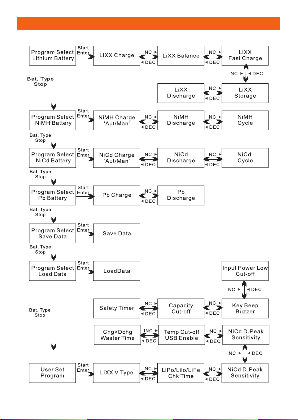
Initial Parameter Set Up (User Set Program)
The Sigma EQ Hyper will be operated with the default values of the essential user
settings when it is connected to a power source for the first time. The screen displays the
following information in sequence and the user can change the value of the parameters
on each screen. In order to alter the initial value in the program, press the Start/Enter
key and the light will flash. Change the value with the INC>or<DEC key. The value will be
stored by pressing the Start/Enter key once.
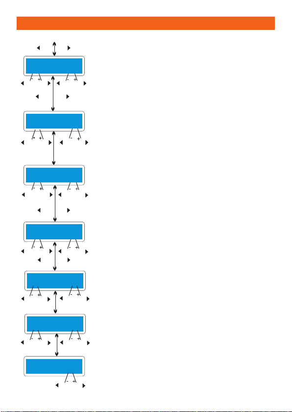
This screen informs you of its designation.
The screen displays the voltage of a Lithium battery. There are
three kinds of Lithium battery; Li-Fe (3.3V), Li-ion (3.6V) and Li-Po
(3.7V). It is very important that the battery is checked carefully
and set up correctly. If it is different from a correct value and the
charger is set up incorrectly, the battery can explode during the
charge process.
The Sigma EQ Hyper will recognise the cell count of the
Lithium battery automatically at the beginning of the charge
or discharge process to avoid the use of an incorrect setting.
However, deeply discharged batteries can be perceived
incorrectly. To prevent this error, the time term can be set to
verify the cell count by the processor. The cell count will read
correctly after 10 minutes. For a battery with a larger capacity,
you may extend the time term. If the time term is too long
for a battery with a smaller capacity, then the cell count will
be erroneous and will cause a false result. If the processor
recognizes the cell count is incorrect at the beginning of the
charge or discharge process, you may extend the time.
On most occasions it is best to use the default count.
This shows the trigger voltage for automatic charge termination
of NiMH and NiCd battery. The effective value ranges from 5
to 20mV per cell. If the trigger voltage is set higher, there is a
possibility of premature termination. Please refer to the technical
specification of the battery. (NiCd default: 12mV/cell, NiMH
default: 7mV/cell)
An additional optional feature is the temperature probe which
is in contact with the surface of the battery. The temperature
cut-off option can be on or off. If this setting is on, the maximum
temperature must be set. When the battery reaches this
temperature during operation, the process will be terminated to
protect the battery.
USER SET
PROGRAM
LiFe
V.Type 3.3v
LiPo/LiIo/LiFe
CHK Time 10 min
NiMH Sensitivity
D.Peak Default
NiCd Sensitivity
D.Peak Default
Temp. Cut-Off
ON 80C
INC
INCINCDEC DEC
INCDEC
INCDEC
INCDEC
INCDEC
DEC INC INCDEC
INC
DEC
DEC INC
- 12 - - 13 -
When the battery is in the process of being charged and
discharged it can often become warm after the charge or
discharge period. The program can insert a time delay to
occur after each charge and discharge process to allow the
battery adequate time to cool down before being subjected to
the next process. The value ranges from 1 to 60 minutes.
The trickle charge mode can be set to either on or off. If it
is set to on, the charger will automatically supply the trickle
charge current to achieve the full charge without overheating
the battery after the fast charge has been terminated.
When the charge process is started, the integral safety
timer automatically starts running at the same time. This
is programmed to prevent overcharging the battery. If the
battery is faulty or if the termination circuit cannot detect that
the battery is full, the value for the safety timer should be
generous enough to allow a full charge of the battery.
This program sets the maximum charge capacity that will
be supplied to the battery during charge. If the delta-peak
voltage is not detected or the safety timer has expired for any
reason, this feature will automatically stop the process at the
selected capacity value.
Initial Parameter Set Up (User Set Program- Continued)
Waste time
CHG/DCHG 5min
NiMH/NiCd/Pb
Trickle 100mA
Safety timer
ON 120min
Input power low
Cut-off 10.0V
Key Beep ON
Buzzer ON
Back-Light
100%
DEC INC
DEC DEC
DEC
INC INC
INC
DEC INC DEC INC
DEC INC DEC INC
DEC INC
DEC INC DEC INC
DEC INC
Capacity Cut-Off
ON 5000mAh
The beep sounds every time the buttons are pressed to
confirm your action. The beep or melody sounds at various
times during operation are to alert you to different mode
changes. These audible sounds can be on or off.
This program monitors the voltage of the input DC battery.
If the voltage drops below the set value, the operation will
forcibly terminate in order to protect the input battery.
The brightness of the LCD screen can be adjusted during
the charge process.
DEC INC
DEC INC
DEC INC
DEC INC
DEC INC

- 12 - - 13 -
Lithium Battery (Li-ion/Li-Po/Li-Fe) Program
The following programs are only suitable for charging and discharging Lithium
batteries with a nominal voltage of 3.3v, 3.6v and 3.7v per cell. These batteries need
to adopt different charge techniques which are referred to as; the constant voltage
(CV) and constant current (CC) methods. The charge current varies according to the
battery’s capacity and performance. The final voltage of the charge process is also very
important; it should be precisely matched with the charged voltage of the battery. They
are 4.2V for Li-Po, 4.1V for Li-ion, and 3.6V for Li-Fe. The charge current and optimal
voltage must always be correct for the cell count set in the charge program. To alter the
parameter value in the program, press the Start key to make it flash, then change the
value with the INC or DEC key. The value will be stored by pressing the Start key once.
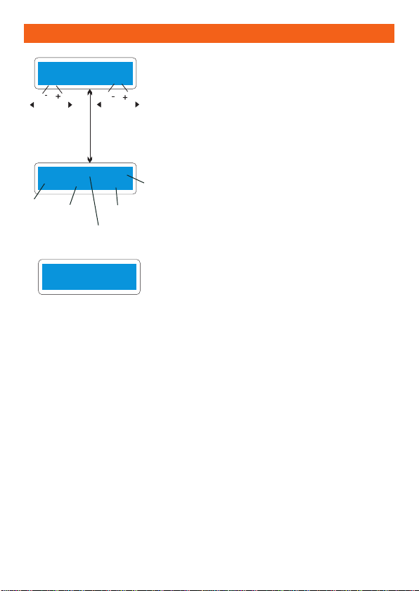
In order to identify the type of battery in use, the
information will be visible on screen. The left side
of the first line will show the type of battery that
has been selected by the user settings. The value
on the left side on second line sets the charge
current. The value on the right side of second line
sets the voltage of the battery pack. After setting
the current and voltage press and hold the Start
key for over 3 seconds to start the process (Charge
current: 0.1~10.0A, Voltage:1~6series).
This shows the number of cells than can be set
up and the amount the processor detects. 'S:'
represents the number of cells selected by you at
the previous screen. If both numbers are identical
you can start charging by pressing the Start button.
If not, please press the Batt type button to go back
to previous screen. The quantity of cells within the
battery pack then needs to be counted carefully.
The screen shows the present situation during the
charge process. To stop charging press the Batt
type key once.
Charging a Lithium Battery
LiPo BALANCE
2.0A 11.1V(3S)
R: 3SER S:3SER
CONFIRM (ENTER)
Li3s 1.2A 12.59V
BAL 022:43 00682
DEC INC DEC INC
Batt type
Stop
Start
Enter
‘>3 Seconds’
Start
Enter
Number
of
Cells
Charging
Time
Charging
Current
Battery
Voltage
Charged
Capacity

- 14 - - 15 -
Charging a Lithium Battery in Balance Mode (Continued)
The value displayed on the left side on the second line sets
the charge current. The value on the right side on the second
line sets the nominal voltage of the battery pack. After setting
the current and voltage, press the Start key for more than
3 second to start the process (Charge current :0.1~10.0A,
Voltage:1~6 series).
The number of cells that have been set up and detected by
the processor should now be visible where ‘R’ is shown. 'R:'
represents the number of cells found by you in the previous
screen. If both numbers are identical, the charging process
can begin.
If the numbers are not the same, the Batt type button should
be pressed, which will lead back to the previous screen. The
number of cells within the battery pack then needs to be
counted carefully.
The screen will show the situation throughout the charge
process. To stop charging press the Batt type key once.
Charging a Lithium Battery in Balance Mode
This is used to balance the individual cell voltages within a Lithium battery pack. In order to do this,
the battery pack being charged should have an individual cell connector lead/plug. This is usually
called the ‘balance’ plug and there are various types. The balance plug should be connected to the
appropriate port on the right side of the charger, usually via a short lead and a suitable adaptor board
that fits your battery pack. There are four types, TP, XH, EH and PQ. A TP board and lead is supplied
and other boards are available as optional extra items. The individual sockets in the side of the charger
are the XH style and no adaptor board is needed. The main battery output plug should be connected
to the output sockets of the charger. In this mode, the charging process will be different from the
ordinary charging mode in the correct polarity. The internal processor of the charger will monitor the
voltages of each cell in the battery pack and will control the charging current that is fed to each cell so
that voltages match as much as possible. It is always recommended to charge Lithium battery packs
in this way.
LiPo BALANCE
2.0A 11.1V(3S)
R:3SER S:3SER
CONFIRM (ENTER)
Li3s 1.2A 12.59V
BAL 022:43 00682
Start
Enter
DEC INC DEC INC
Number
of
Cells
Charging
TimeCharging
Current
Battery
Voltage
Charged
Capacity
Batt type
Stop
Start
Enter
‘>3 Seconds’
Individual Cell Connection Diagram (Pin-Assignment of 8-Pin)

- 14 - - 15 -
‘FAST’ Charging with a Lithium Battery
'FAST' charging a Lithium battery occurs when the charging current gets smaller as
the process goes to the end of the Lithium battery charging process. By finishing the
charging process earlier, this program will eliminate certain parts of the CV process. The
charging current will go to 20% of the initial value to end the process while the normal
charge will go to 10% during the CV term. The charging capacity may be slightly smaller
than the normal charging capacity, but the process time will be reduced.
The storage option can be used for charging or discharging a Lithium battery that will
not be used immediately. The program will charge or discharge the battery to any
voltage depending on the voltage of the battery at its initial stage. There are a variety of
different types of Lithium battery with various voltages, 3.75V for Li-ion, 3.85V for Li-Po
and 3.3V for Li-Fe per cell. If the voltage of the battery at its initial stage of charging is
over the voltage level of storage, the program will commence discharge.
‘STORAGE’ Control Lithium Battery
The charging current and the voltage can be set
whilst the battery pack is being charged. When
the Start/Enter button is pressed, the voltage
confirmation will be displayed. In order to confirm
this amount, press the Start/Enter button again to
begin charging.
The screen will display the present state of ‘FAST’
charging. In order to cease charging, press the
Batt type/stop key once.
The current and the voltage of the battery pack can
be set up to be charged. The current will be used
to charge or discharge the battery to reach the
optimum ‘storage’ voltage.
This screen will show the progress in which the
charging process is in throughout. To stop charging
press the Batt type/Stop key once.
LiPo FAST CHG
2.0A 11.1V (3S)
Li3s 2.0A 12.59V
FAS 022:43 00682
LiPo STORAGE
2.0A 11.1V (3S)
Li3s 2.0A 12.59V
STO 022:43 00682
DEC INC DEC INC
DEC INC DEC INC
Batt type
Stop
Start
Enter
‘>3 Seconds’
Number
of
Cells
Elaposed
Time
Current
Battery
Voltage
Supplied
Capacity
Start
Enter
‘>3 Seconds’
Batt type
Stop
Charge
or Discharge
Number
of
Cells
Elapsed
Time
Current
Voltage
Battery
Supplied
Capacity
Charge
Current

- 16 - - 17 -
Please note: The value of discharge current on
the left side of screen may not exceed 1C. The
final voltage on the right should not be under the
voltage level that is recommended by the battery
manufacturer. This is to avoid deep discharging.
To start to discharge press the Start/Enter key for
more than 3 seconds. (Discharge current: 0.1-5.0A)
The screen will then show the present state of
discharge. To stop discharging, press the Batt type/
Stop key once.
Discharging a Lithium Battery
*Voltage balancing and monitoring during discharge
This process monitors the voltage of individual cells during 'storage-mode' and
'discharge' of a Lithium battery pack. It attempts to normalise the voltages to an equal
level. For this feature, the balance plug of the battery pack should be connected to the
balance port in the charger. This may need an appropriate adaptor board. If the voltage
of any one or more cells varies abnormally during the procedure, the Sigma EQ Hyper
terminates the process with an error message. If this happens, the battery pack contains
the faulty cell, or there is a faulty connection in the cable or plug. You can easily identify
which cell is faulty by the pressing INC> button whilst error message is displayed.
If the processor has found that the voltage of one
cell in the Lithium battery pack to be too low.
In this instance, the 4th cell has a fault. In the
case of a connection-break in the cable or plug,
the voltage value may show zero.
LiPo FAST CHG
2.0A 11.1V (3S)
Li3s 2.0A 12.59V
FAS 022:43 00682
BATTERY VOL ERR
CELL LOW VOL
C1:3.50 C2:3.52
C3:3.48 C4:1.82
C5:3.46 C6:3.50
C7:3.42 C8:3.48
DEC INC DEC INC
INC
INC
Batt type
Stop
Start
Enter
‘>3 Seconds’
Number
of
Cells
Elapased
Time
Current
Battery
Voltage
Supplied
Capacity
Charge
current

- 16 - - 17 -
These programs are for charging or discharging NiMH (Nickel-Metal-Hydride) or NiCd
(Nickel-Cadmium) batteries commonly used for R/C model applications. To alter the
value at the display, press the Start/Enter key to make it flash, then the value needs to
be adjusted using the INC> or <DEC keys. The value will be stored by pressing the
Start/Enter key once.
To start the process, press and hold the Start/Enter button for more than 3 seconds.
Charging NiCd/NiMH Battery
Set the discharge current on the left hand side of the
screen and the final voltage on the right hand side.
The discharge current ranges from 0.1 - 5.0A and the
final voltage ranges from 0.1 - 25.0V. In order to start
the process, press and hold the Start/Enter key for
more than 3 seconds.
When the screen displays the current state of
discharge, it is possible to alter the discharge current
by pressing the Start/Enter key during the process.
Once the current value has been changed it can be
stored by pressing Start/Enter button again. To stop
discharging, press the Batt.Type/ Stop key once.
The audible sound will indicate the end of the
process.
Discharging NiCd/NiMH Battery
This program simply charges the battery using
the current that has been set in 'Auto' mode, the
upper limit of charge current will need to be set to
avoid feeding a high current that may damage the
battery. Some batteries with a small capacity can
have a higher charge current from the processor in
automatic charge mode. Whilst in 'Man' mode, the
battery will be charged to the set limit on the display.
Each mode can be switched by pressing the INC>
and <DEC buttons simultaneously when the current
field is flashing.
The screen displays the current state of charging.
To stop this process, press the Batt. Type/Stop key
once. The audible sound should indicate the end of
the process.
NiMH CHARGE AUTO
CUR LIMIT 5.0A
NiMH 2.0A 7.42V
CHG 022:45 00890
NiMH DISCHARGE
3.0A 11.5V
NiMH 2.0A 7.42V
DSC 022:45 00890
DEC INC
DEC INC DEC INC
Batt type
Stop
Start
Enter
‘>3 Seconds’
Batt type
Stop
Start
Enter
‘>3 Seconds’
- 18 - - 19 -
Charge-Discharge & Discharge-Charge Cycle NiCd/NiMH Battery
Set the sequence on the left hand side of the
screen and the number of cycles on the right.
This function can be used to balance, refresh and
break-in a battery. There will be a brief cool-off
period that is already fixed in the 'User setting'
after each charge and discharge process. The
cycling number ranges from 1 - 5.
To stop the process, press the Batt.Type/Stop key
once. The current for the discharge or charge can
be changed by pressing the Start/Enter key once
during the process. The audible sound will indicate
the end of the process.
At the end of the process, the charged and
discharged capacities of the battery are visible at
each cyclic process. By pressing the INC> or <DEC
buttons, the screen will show the result of each
cycle in order.
NiMH CYCLE
DCHG>CHG 3
NiMH 2.0A 7.42V
D>C 022:45 00890
DCHG 1 1314mAh
CHG 1 1430mAh
DEC INC DEC INC
Batt type
Stop
Start
Enter
‘>3 Seconds’
Number
of
Cells
Elapased
Time
Discharged
Capacity
Battery
Voltage
Discharge
Current

- 18 - - 19 -
Charging a Pb Battery
This program is for charging a Pb (lead-acid)
battery with a nominal voltage from 2 - 24v.
Pb batteries are very different to NiCd or NiMH
batteries. They can only deliver relatively low
current in comparison to their capacity and
similar restrictions apply to charging. The
optimal charge current will be 10% of the
capacity. Pb batteries must not be charged
rapidly. Always follow the instructions supplied
by the manufacturer of battery.
In order to alter the parameter value in the
program, press the Start key and you should see
it flash. Change the value with the INC> or <DEC
keys. The value will be stored by pressing the
Start key once.
Discharging a Pb Battery
Set the discharge current on the left and the
final voltage on the right. The discharge current
ranges from 0.1 to 5.0A. To start the process,
press and hold the Start key for more than 3
seconds.
The screen will display the current state of
the discharge. You can change the discharge
current by pressing the Start key during the
process. Once the current value has been
changed, store it by pressing the Start button
again. To stop discharging, press the Batt type
key once. The audible sound will indicate the
end of the process.
Pb DISCHARGE
4.0A 12.0VP
Pb-6 4.0A 7.42V
DSC 022:43 00682
DEC INCDEC INC
Batt type
Stop
Start
Enter
‘>3 Seconds’
Battery
Type
Elapased
Time
Battery
Capacity
Charged
Capacity
Charge
Current
Pb CHARGE
4.0A 12.0V (6)
Pb-6 4.0A 12.59V
CHG 022:43 00682
Battery
Type
Elapsed
Time
Battery
Capacity
Charged
Capacity
Charge
Current
DEC INC
Batt type
Stop
Start
Enter
‘>3 Seconds’
- 20 - - 21 -
The Sigma EQ Hyper has data storage and load programs for your convenience.
This feature can store up to 10 different preset battery regimes. They are stored by
number and represent the individual specification of the batteries that you are using
regularly. They can be selected for charging or discharging without setting up the
program again. To set up the parameter value in the program, press the Start/Enter key
until the flashing value is visible and then change the value with the INC> or < DEC keys.
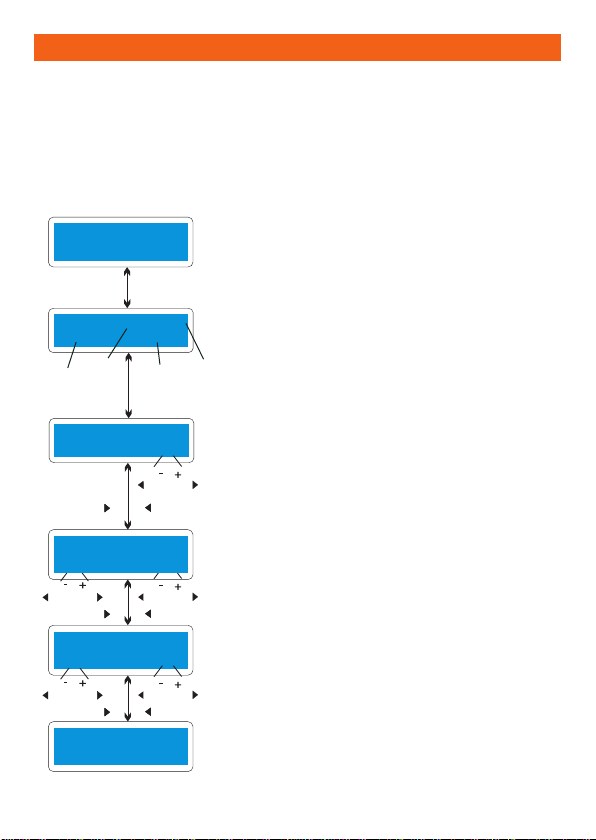
Save Data Program
The parameter value set up in this screen does
not affect the charge or discharge process. They
only represent the specification of the battery. The
following screens will automatically be displayed
exactly matched to the battery type you set up. The
example shows the battery pack of NiMH, 12 cells
and 3000mAh capacity.
Set up the charge current for manual charge mode
or use the current limit for automatic charge mode.
Each mode can be switched by pressing the
INC> and <DEC buttons at the same time when
the current field is flashing.
Saving the data.
DEC INC
DEC INC DEC INC
DEC INC
DEC INC
INC DEC
DEC
INC
DEC
INC
PROGRAM SELECT
SAVE DATA
SAVE [01] NiMH
14.4V 3000mAh
NiMH CHARGE At*
CUR LIMIT 5.0A
NiMH DISCHARGE*
4.0A 11.0V
NiMH CYCLE *
DCHG>CHG 3
SAVE . . .
Battery Type
Stop
Voltage Capacity
Data
Number
Type of
Battery
Start
Enter
‘>3 Seconds’
Start
Enter
Setting up the sequence of charge and discharge
and the cycling number.
Setting up the discharge current and final voltage.
Table of contents
Languages:
Other Pro-Peak Batteries Charger manuals


