Ocular IQ WALLBOX User manual

OCULAR IQ WALLBOX
& IQ SOLAR
INSTALLATION GUIDE
IOCAW13-7S/7T & IOCAW13-22S/22T
IOCAW13-7S/7T- SOLAR & IOCAW13-22S/22T- SOLAR
OCULAR CHARGING AUSTRALIA
Email: sales@ocularcharging.com.au
Web: www.ocularcharging.com.au

OCULAR IQ WALLBOX INSTALLATION
Follow steps 1-4
OCULAR IQ SOLAR INSTALLATION
Follow steps 1-10

1
CONTENTS
24
27
27
SPECIFICATIONS
PRODUCT OVERVIEW
SAFETY INSTRUCTIONS
INSTALLATION
LCD DISPLAY DETAILS
TROUBLESHOOTING
MAINTENANCE AND REPAIR
.............................................................................
.................................................................................
....................................................................
......................................................................................4
..............................................................................5
............................................................................6
...........................................................................................7
NOTES BEFORE INSTALLATION
TOOLS REQUIRED
OVERVIEW OF STEPS
STEP ONE - CHECK BOX CONTENTS
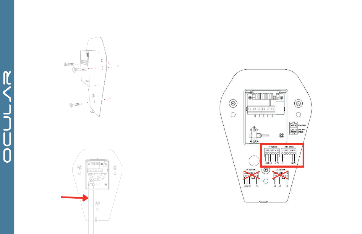
STEP TWO – WALL MOUNTING & WIRING
STEP THREE – INSTALL THE CHARGER
STEP FOUR - INTERNET CONNECTION
WIRING DIAGRAM
STEP FIVE - CT CLAMP INSTALLATION & WIRING
STEP SIX - CT CLAMP SPEC REQIREMENTS
STEP SEVEN - CT CLAMP CONFIGURATION
STEP EIGHT (A) - CT SINGLE PHASE SETUP
STEP EIGHT (B) - CT THREE PHASE SETUP
STEP NINE - CT CLAMP CONFIGURATION (CONTINUED)
STEP TEN - VERIFY THE INSTALLATION
......................................................................................7
............................................................................................................7
...........................................................................................................7
............................................................................7
............................................................8
................................................................9
...........................................................................9
..................................................................................................12
....................................................13
................................................................13
.................................................................15
...................................................................16
..................................................................18
..........................................20
......................................................................22
For information on how to charge your electric vehicle, refer to the documentation
provided with your vehicle.
IMPORTANT !
READ THIS ENTIRE DOCUMENT BEFORE INSTALLING OR USING
THE CHARGER. FAILURE TO DO SO OR TO FOLLOW ANY OF THE
INSTRUCTIONS AND WARNINGS IN THIS DOCUMENT CAN
RESULT IN FIRE, ELECTRICAL SHOCK, SERIOUS INJURY OR DEATH.
THE CHARGER MUST BE INSTALLED BY A QUALIFIED
ELECTRICIAN.
THE ENTIRE INSTALLATION MUST COMPLY WITH THE LATEST
AS 3000 STANDARDS
3
SOLAR INSTRUCTIONS

230V AC single-phase: LIVE, NEUTRAL ,and EARTH. 400VAC three-phase:L1,L2,L3,NEUTRAL,and EARTH.
Maximum 32A and 7kW Maximum 32A and 22kW
50-60 Hz
AC 30mA, DC 6mA
OCPP 1.6J, 2.0
SAE J1772, IEC62196 Type-2
1 x Physical Button
ISO 14443 A/B
2.8’’ LCD
Ethernet, WLAN
-30°C to 50°C
-40°C to 70°C
495 x 375 x 330 mm
6.7Kg 7.7Kg
2
SPECIFICATIONS
IP55
EN IEC 61851-1, EN IEC 61851-21-2, EN 61008-1, IEC 62955
All specifications and descriptions contained in this document are verified to be accurate at the time of printing. However, because continuous
improvement is a goal at Ocular Charging, we reserve the right to make product modifications at any time.
IOCAW13-7S / 7T | IOCAW13-7S / 7T-SOLAR IOCAW13-22S / 22T | IOCAW13-22S / 22T-SOLAR
ELECTRIC VEHICLE CHARGER
SPECIFICATIONS
4
Model
Voltage and Wiring
Current and Power
Frequency
Internal RCD
Data Protocol
Charging Connector
Buttons
RFID
Display
Network Connectivity
Working Temperature
Storage Temperature
Working Humidity
Enclosure Dimensions
Shipping Dimensions
Shipping Weight
IP Rating
Certifications
380 x 288 x 141 mm
5% - 95% without condensation

3
FEATURES
ELECTRIC VEHICLE CHARGER
SELF-MONITORING AND RECOVERY
OCPP 1.6J, 2.0 FULL PROFILES & SMART
CHARGING SUPPORT
PRODUCT OVERVIEW
The charger will automatically resume charging after a minor fault
such as OVP, UVP, OTP or OCP, with no user intervention required.
The charger supports OCPP 1.6J, 2.0 including the latest smart
charging profile to balance the load of charging stations with limited
power supply.
1
2
3
4
5
6
LED indicator
2.8’’ LCD screen
Status indicator, Fault, Online, Charging
RFID card reader
Physical button
Type-2 charging socket
No
.
Item
WORKPLACE PEDESTAL CHARGER
5
1
3
4
2
6
5

4
SAVE THESE IMPORTANT SAFETY INSTRUCTIONS
Do not install or use the charger near flammable, explosive, harsh, or combustible
materials, chemicals, or vapors.
Turn off input power at the circuit breaker before installing or maintaining.
Do not use or stop using the charger if it is defective, appears cracked, frayed,
broken or otherwise damaged, or fails to operate.
Do not attempt to open, disassemble, repair, tamper with, or modify the charger.
The charger is not user serviceable. Contact iocharger or authorized service
provider for any repairs.
Do not touch the charger sockets with sharp metallic objects, such as wire, tools or
needles.
Do not put fingers into the charger sockets.
Do not use this charger if the EV charging cable is frayed, has broken insulation, or
displays any other indication of damage.
Do not use this charger if the enclosure or the EV charging connector is broken,
cracked, open, or shows any other indication of damage.
This document contains important instructions and warnings that must
be followed when installing and maintaining the workplace pedestal
charger
The charger should be installed only by a qualified approved technician.
Make sure that the materials used and the installation procedures follow local
building codes and safety standards.
Incorrect installation and testing of the charger could potentially damage either the
vehicle’s Battery and/or the charger itself. Any resulting damage is excluded from
the warranty for both the vehicle and the charger.
Do not operate the charger in temperatures outside its operating range of -30°C to
+50 °C.
Ensure that the EV charging cable is positioned properly to the charging sockets.
Do not use cleaning solvents to clean any of the charger’s components.
WARNINGS: CAUTIONS:
ELECTRIC VEHICLE CHARGER
SAFETY INSTRUCTIONS
Ferrules must be used to
ensure warranty is valid
6

5
IN ST ALLA TION
ELECTRIC VEHICLE CHARGER
TOOLS REQUIRED
OVERVIEW OF STEPS
NOTES BEFORE INSTALLATION STEP ONE - CHECK BOX CONTENTS
Philips #2 screwdriver
Electric drill
TURN OFF THE POWER SUPPLY. Then follow these steps to install
the Charger:
1. Check box contents
3. Wall mounting & wiring
4. Install the charger
5. Internet connection
2.CT Clamp Spec Requirements
6. CT Clamp installation & wiring
7. CT Clap Configuration
Rated residual operating current not exceeding 30 mA
Type-A
The charger should be protected by an external Residual Current
Device (RCD) to be installed in the upstream circuit which complies
with the following:
Ferrule crimps x 4
User Manual x 1
EV Charger with backplate
Ferrule crimps x 3
If any of these components are damaged or missing, contact Ocular
Charging.
Expansion screws x 3
Ferrule crimps must be used to ensure warranty is valid
8. CT Single phase setup
9.CT Three phase setup
10. Verify the installation
3
FEATURES
ELECTRIC VEHICLE CHARGER
7

6
STEP TWO– WALL MOUNTING & WIRING
1.
2. Connect the cable through the bottom of the junction box ensure
conduit is connected to the bottom of the power box
Remove the backplate from the charger and mount the
backplate to the wall
3. Electrical Connection
In Australia only the TN network is used, as shown on the label on the
back plate.
conduit
Ferrule crimps must be used to ensure warranty is valid
8

Ethernet - Commercial, Apartment or Home installations
Please connect the ethernet cable to the WAN port this should connect
automatically to the internet if there's no IT restrictions,
( if static IP address is required please refer to the Ocular Configuration manual)
(See Ocular or local supplier for manual)
7
IN ST ALLA TION
STEP THREE – INSTALL THE CHARGER STEP FOUR – INTERNET CONNECTION
1.
2.
Install the charger to the backplate
Fix the charger and backplate with screw
Wi-Fi
(Not recommend in commercial installations or apartments.) Please
note: unstable/weak WI-FI connection may cause undesired
operational issues. Please call installer if Wi-fi signal is insufficient.
Screw
Button
9

8
INSTALLATION ELECTRIC VEHICLE CHARGER
Wi-Fi Connection Guide-
Do not change settings other than outlined below as this may affect
operations.
Step 1: Find the chargers’ local hotspot
This hot spot will have the following SSID: IOC – 2.4GHz - ******
The password for this Hotspot is: IOC12345
Step 2: Navigate to the web-interface of the Ocular Charger
After being connected to the Hotspot, open Microsoft Edge or Google
Chrome and navigate to: 192.168.10.1:8900
The web interface will ask for Username and Password, the information is:
Username : install
Password : installer123
Step 3: Navigate to the Network and set up WIFI configuration
Ocular charger support connection via WiFi. Simply press the “Scan”
button to start scanning for available WiFi network
After this, press the down arrow in the drop list to see all the available
WiFi networks
Choose the Wi-Fi SSID that you prefer, and then input the Wi-Fi Password
If Static IP address is required, simply disable DHCP under WiFi section
and put in the Static IP Address for the device
Step 4: Submit then reboot the charger to apply changes
10
10

8
10
11
Please note:
Step 5 and onwards
is for Ocular IQ Solar
Installation only.
11

SDaodwaiojdoaiwjd
SDaodwaiojd
oaiwjd
Power connection
Internet connection (required for smart functions)
Regarding the installation of the Ocular IQ Solar, each charger will need a power connection and an additional internet connection to allow smart charging with energy tracking , smart
control and load management.
Regarding the power connection of the chargers, each charger will have its own designated circuit from the distribution board as per required in Appendix P, AS 3000:2018 Australia
Standard for EV charging stations. We recommend 40A type A RCBO for the IQ Solar to avoid nuisance tripping
Regarding the Internet connection, we recommend running an Ethernet cable from the communication infrastructure comms cabinet to the charger for internet connection. Wi-fi can be
used when the signal is strong. Above 3 bars
4
ELECTRIC VEHICLE CHARGER
CT Clamp Connection
Distribution Board
Wi-Fi or Ethernet Connectivity
Residential/Home Wiring
8
INSTALLATION ELECTRIC VEHICLE CHARGER
10
12

CT1
CT2
CT3
RED
P1
P2
P3
BLACK
N1
N2
N3
1. Please run the CT clamp wires through the grey gland/hole
located at the bottom of the charger.
2. Please connect internally following this diagram:
STEP FIVE– CT CLAMP INSTALLATION & WIRING
13

Description
Current Transformer
Rated Current Ratio
100A:50mA
TYPE
IOCCT100
Electrical Specifications
Mechanical Dimensions in mm
Same polarity:*--*
Direction for use
:
Rated Primary Current (A)
100A
Secondary Current (mA)
50mA
Maximum Current Imax (A)
120A
Rate Transformation Ratio
2000:1
Power-Frequency Withstand
Voltage
4000 Vrms
Current Error
±0.5%
Rated Phase Displacement
≤80ʹ
Rated Frequency
50/60Hz
Rated Short-Time Thermal
Current
400A
(
≤1s
)
Rated Resistive Burden (Ω)
≤ 20Ω
Insulation Resistance (MΩ)
>
500MΩ
Mechanical Specifications
Encapsulant
Epoxy Resin
Weight (g)
110g
Tolerance
(
mm
)
±1.5
Storage Temperature (℃)
-40℃<T<+85℃
Working Temperature (℃)
-25℃<T<+75℃
Working Humidity
0-90% (no
condensation)
Enclosure Flame Retardant
Grade
UL94 V-0
8
STEP SIX – CT CLAMP SPEC REQUIREMENTS
Prior to setting up the CT clamps, please ensure that you have the correct CT
and CT Ratio setup.
Only use CT clamps provided by Ocular – The wrong CT clamps will cause a
misreading and void warranty. If you must use your own CT please speak to
Ocular and confirm suitability.
The Rate Transformation Ratio must be 2000:1 or the CT clamps will generate
incorrect readings.
INSTALLATION
10
14

13
STEP SEVEN – CT CLAMP CONFIGURATION
Do not change settings other than outlined below as this may affect
operations.
Step 1: Log in to the configuration page of the web page.
Step 2: Go to the 'Advanced' section
Step 3: Navigate to the balance page.
Step 4: In 'Mode' , select 'Master TCP Server'.
Step 5: In 'Data Format', select 'Modbus RTU' and the TCP port will
automatically allocate the default address of 22401.
Step 6: In 'Power Type', select 'Gateway'
Step 7: Set 'SelfGroupId' to 1
Step 8: Set 'JoinGroupId' to -1
Step 9: Set Basic Broadcast Port to 10000
Step 10: Turn on the "Solar" switch and set the energy mode to "Full" by
default customer will be able to change this on the APP. Do not change on
the backend
15

STEP EIGHT (A) – CT SINGLE PHASE SETUP
Do not change settings other than outlined below as this may
affect operations.
Step 1: Turn on the HUB1 switch.
Step 2: Set the address to 254.
Step 3: Turn off the 3-Phase switch.
Step 4: Set the CT1 position to "Main." Set the ratio to
2000:1 and set the phase to default to "L1."
The CT clamp is connected to the P1-N1 terminals
using the red and black signal wires.
The CT clamp is installed in the main MCB input
terminal at the L1 position, with the direction pointing
from the grid to the home as below
INSTALLATION
10
16

17
SINGLE PHASE CT INSTALL

Do not change settings other than outlined below as this may affect
operations.
Step 1: Turn on the HUB1 switch.
Step 2: Set the address to 254.
Step 3: Turn on the 3-Phase switch.
Step 4: Set the CT1 position to "Main." Set the ratio to 2000:1 and
set the phase to default to "L1."
STEP EIGHT (B) – CT THREE PHASE SETUP
18
CT Clamp 1, CT Clamp 2, and CT Clamp 3 are
connected to the P1-N1, P2-N2, and P3-N3
terminals respectively using the red and black signal
wires.
CT Clamp1, CT Clamp2, and CT Clamp3 are installed
in the main MCB input terminals at the L1, L2, and L3
positions respectively, with the direction pointing
towards the direction of the grid.

15
THREE-PHASE CT INSTALL
19

STEP NINE – CT CLAMP CONFIGURATION
(Continued)
Rated Current: This is the maximum current that the main MCB can
handle.
Safe Current: This is the safe current reserved to prevent the circuit
from overloading. The actual available current for the charging station
is calculated as follows: Actual available current = Rated current - Safe
current - Load current.
Limit Total Charger Current: This is the actual available current in the
circuit, which is equal to the rated current plus the solar power
generation current. The default maximum value is usually 65535. This
should not be changed.
Grid Current (*please note scale is 0.1A so 1 Amp is a value of 10*)
1.
2.
3.
For example, a 80Amp distribution board should have
Rated Current – 800
Safe Current –80 (10% safety is recommended as a minimum This
can be higher is required. The charger will load manage and stop
charging completely if it sees load above 720 which is 72 Amps.)
20
This manual suits for next models
9
Table of contents
Other Ocular Batteries Charger manuals
Popular Batteries Charger manuals by other brands

Synthes
Synthes Universal Battery Charger II user manual

Schumacher
Schumacher SC1324 owner's manual

LSL
LSL AMP-L-START installation instructions

FONESTAR
FONESTAR SCI-790C quick start guide

Analytic Systems
Analytic Systems BCD600-32-12 Installation & operation manual

XD XCLUSIVE
XD XCLUSIVE Ontario P308.42 Series manual