Safety
Quantum:EV OpenCharge EVQROCM-01-V01-R0 Installation and Operation Manual
Page 4of 21 September 2020
Safety
This manual is specifically applicable to the Quantum:EV OpenCharge electric vehicle
charging product and is provided as a guide to its installation and operation.
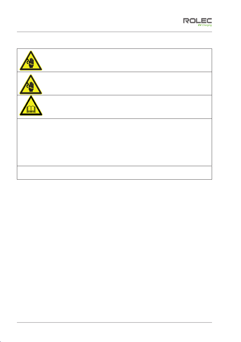
WARNING: Electrical Power
Make sure electrical power is isolated BEFORE starting this procedure.
xTurn power OFF at SOURCE.
IMPORTANT: Installers and End Users must read and understand the content
of this manual before installation and/or use of the product.
Installation must only be performed by someone who is properly qualified and
competent to do so in accordance with the current legislation in force in the
geographical location of the installation.
xIf the advice in this manual is not understood, contact Rolec for further advice
and/or training BEFORE attempting installation/operation of the equipment.
xRolec Services Ltd cannot accept any responsibility for improper installation or any
problems arising from improper installation.
NOTE: Damage to the equipment, connected systems or to property caused by
improper installation are the responsibility of the installer.
xThe information provided in this manual must ONLY be used with the model(s) listed on
page 2 of this manual.
xThe information provided in this manual must NOT be used with any other product.
xThe content of this manual may be updated as required.
xDo NOT use the equipment for anything other than its intended purpose.
xDo NOT modify the equipment unless specifically instructed to do so by the
manufacturer.
xDo NOT attempt to repair the equipment unless specifically instructed to do so by the
manufacturer.
xThis product is electrically safe when in normal use. To maintain electrical safety, the
body enclosure of the product (access covers) must be secured in their correct
location using the supplied fasteners and the seal must be sufficient to maintain the IP
rating of the enclosure.
xFasteners used to mount the product in its working location must be sufficient for the
task and the specific mounting point.
xIf required, fasteners used to mount the product in its working location should be
sealed to maintain the IP rating of the enclosure.
xIf required, cable entry apertures should be sealed to maintain the IP rating of the
enclosure.
xDamage to the body enclosure, access covers, seals may render the product unsafe.
The product must be electrically isolated and NOT used until appropriate remedial
action has been performed.
Product Overview
EVQROCM-01-V01-R0 Installation and Operation Manual Quantum:EV OpenCharge
September 2020 Page 5of 21
Safety Advice within this Manual
Rolec manuals use a system of warnings, cautions and notes.
xWARNINGS concern the safety of installers/end user and will be given before the
detail/instructions in the manual.
xCAUTIONS concern the potential for damage to the equipment and will be given
before the detail/instructions in the manual.
xNOTES are given to provide additional information and/or to highlight information of
importance. They will be given either before or after the detail/instructions as
appropriate and may use different wording (such as IMPORTANT) where emphasis is
required.
Warnings, Cautions and Notes may be repeated several times as appropriate and may
be preceded by a hazard symbol where appropriate.
Product Overview
The Quantum:EV OpenCharge is an OCPP compliant, smart charging unit which has been
designed to provide the user with a simple, smartphone interactive, EV charging solution
via an online application and/or RFID card/fob. The EV driver/Charger Operator can
control the charging activity of the unit using their mobile phone, and/or RFID card/fob, as
well as allowing them to monitor / record all their charging activity, data and history via
their driver application dashboard.
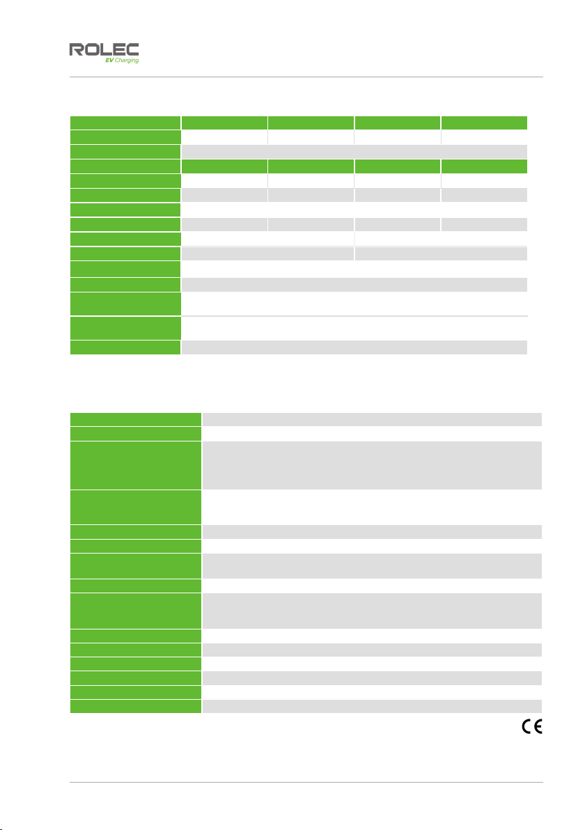
The Quantum:EV OpenCharge is available with the following power options:
Quantum EV OCPP Single Phase - 1x 3.6kW (16A)
Quantum EV OCPP Single Phase - 1x 7.2kW (32A)
Quantum EV OCPP Single Phase - 2x 3.6kW (16A)
Quantum EV OCPP Single Phase - 2x 7.2kW (32A)
Quantum EV OCPP Three Phase (Superfast) - 1x 11kW (16A)
Quantum EV OCPP Three Phase (Superfast) - 1x 22kW (32A)
Quantum EV OCPP Three Phase (Superfast) - 2x 11kW (16A)
Quantum EV OCPP Three Phase (Superfast) - 2x 22kW (32A)
Refer to the Product Specification on page 6 for further details.
Features
xOCPP Compliant
xOLEV Grant Fundable under the Electric Vehicle Workplace Charging Scheme (WCS).
xSmart charging.
xBuilt-in AC overload protection (MCB).
xBuilt-in AC & DC fault protection (RCD).
xBuilt-in LED charging status indicator.
xBuilt-in LED area illumination.
xBuilt-in Class 1 MID compliant kWh metering.
xBuilt-in Modem and roaming sim or Ethernet connection.
xBuilt-in GPRS communication antenna.
xFire retardant & impact resistant design.
xIP Rated.
xcertified.