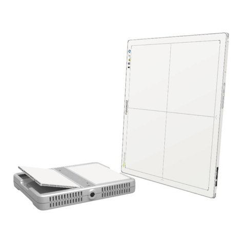
Pro-tec RAPIXX Series Instruction Manual

PROTEC GmbH & Co. KG
In den Dorfwiesen 14, 71720 Oberstenfeld, Germany
Version: 2.0
Effective from: 2020-06-30
Subject to alterations
RAPIXX 2530V1V Wifi Set
RAPIXX 2530V2V Wifi Set
Di ital X-ray detector system
Model/ID: 4486-9-1000L
4487-9-1000L
Installation & User Manual
Ident. No. 5436-0-0004

5045
-
0
-
0001
© 2016 PROTEC GmbH & Co. KG, Oberstenfeld
Comments and questions about the documentation please contact:
PROTEC GmbH & Co. KG
In den Dorfwiesen 14 | 71720 Oberstenfeld
Germany
Tel: + 49 (0) 7062 – 92 55 0
Fax: + 49 (0) 7062 – 92 55 60
E-Mail: protec@protec-med.com
Internet: www.protec-med.com

RAPIXX DR System Installation & User Manual
5420
-
0
-
0004
3
of
20
Table of contents
Pa e
Table of contents ........................................................................................................................... 3
Document Version ........................................................................................................................ 5
Mechanical and Electrical Warnin ............................................................................................ 6
Radiation Warnin ........................................................................................................................ 6
To the User ..................................................................................................................................... 6
Improvement Recommendations .............................................................................................. 6
1
General .................................................................................................................................. 7
1.1 Inspection of delivery packaging ............................................................................................................................................ 7
1.2 Inspection of the scope of delivery ....................................................................................................................................... 7
1.3 System requirements ..................................................................................................................................................................... 7
1.4 Environmental Conditions .......................................................................................................................................................... 7
1.4.1 Operating Conditions ........................................................................................................................................................ 7
1.4.2 Storage Conditions.............................................................................................................................................................. 7
2
Description of the RAPIXX DR-systems ............................................................................ 8
2.1 General Description ......................................................................................................................................................................... 8
2.2 Intended Use ....................................................................................................................................................................................... 8
2.3 Intended User Group ...................................................................................................................................................................... 8
2.4 Combination with other products ......................................................................................................................................... 8
3
Important notes for the preparation of the detector installation ............................... 9
3.1 General Information ........................................................................................................................................................................
3.2 Notes for installing a new digital X-ray system ..............................................................................................................
3.3 Notes for upgrading an existing CR- or analogue X-ray system ..........................................................................
4
Installation .......................................................................................................................... 10
4.1 Check list ............................................................................................................................................................................................. 10
4.2 Connection of the components ........................................................................................................................................... 10
4.3 Setup the network ........................................................................................................................................................................ 10
4.4 W-LAN connection to the Detector ................................................................................................................................... 11
4.5 Copying detector specific data ............................................................................................................................................. 11
4.6 Installation of CONAXX 2 .......................................................................................................................................................... 11
5
Calibration of the DR System ........................................................................................... 12
6
Startup of the DR system.................................................................................................. 13
6.1 First start of CONAXX 2 ............................................................................................................................................................... 13
6.2 Necessary settings in CONAXX 2.......................................................................................................................................... 13
6.3 Licensing of CONAXX 2 .............................................................................................................................................................. 13
6.4 Setup dose indicator for detector ....................................................................................................................................... 14
7
Status information ............................................................................................................ 15
7.1 Daily Operation ............................................................................................................................................................................... 15
7.2 Switch on sequence after changing the battery ....................................................................................................... 15
7.3 Troubleshooting ............................................................................................................................................................................. 15
8
Handlin of the RAPIXX DR system ................................................................................ 16
8.1 Operation of the RAPIXX DR system .................................................................................................................................. 16
8.1.1 Startup order for daily use ........................................................................................................................................... 16
8.1.2 Error during operation with the X-ray generator .......................................................................................... 16
8.1.3 Error during operation with the modality .......................................................................................................... 16
8.2 Operation of the CONAXX 2 software .............................................................................................................................. 16
8.3 Operation of the detector with accessories .................................................................................................................. 16
8.3.1 Handling and change of the battery ..................................................................................................................... 17
9
Safety and Maintenance ................................................................................................... 17
.1 Introduction ...................................................................................................................................................................................... 17
.2 Cleaning and disinfection ......................................................................................................................................................... 17
.3 Checkup and maintenance ..................................................................................................................................................... 18

RAPIXX DR System Installation & User Manual
5420
-
0
-
0004
4
of
20
.3.1 Daily controls prior to or during the unit operation .................................................................................... 18
.3.2 Safety-related controls ................................................................................................................................................... 18
.3.3 Maintenance ........................................................................................................................................................................ 18
10
Liability ................................................................................................................................ 18
11
Guarantee ......................................................................... Fehler! Textmarke nicht definiert.
12
Disposal ............................................................................................................................... 19
13
Electroma netic compatibility (EMC) accordin to EN 60601-1-2 ............................ 19
13.1 General ................................................................................................................................................................................................. 1
13.2 Detector with accessories ........................................................................................................................................................ 1
14
Description of symbols and abbreviations ................................................................... 20
14.1 Symbols ............................................................................................................................................................................................... 20
14.2 Abbreviations ................................................................................................................................................................................... 20

RAPIXX DR System Installation & User Manual
5420
-
0
-
0004
5
of
20
Note
The information contained in this document conforms to the confi uration of the equipment as
of the date of manufacture. Revisions to the equipment subsequent to the date of manufacture
will be addressed in service notes distributed by PROTEC GmbH & Co.KG.
Document Version
Revision Date List of revised pa es Comments
1.0 October 2016 --- First edition Installation &
Operation Manual
2.0 2020-06-30 12; 1 NOTE Calibration new;
Warranty changed

RAPIXX DR System Installation & User Manual
5420
-
0
-
0004
6
of
20
Mechanical and Electrical Warnin
All of the movable assemblies and parts of this equipment should be operated with care and
routinely inspected in accordance with the manufacturer's recommendations contained in the
equipment accompanying documents. Maintenance and service is only to be performed by
technicians authorized by PROTEC GmbH & Co. KG.
Touchin electrical live parts can be lethal.
Do not remove flexible hi h-tension cables from X-ray tube housin or hi h-tension enerator
and/or access covers from X-ray enerator.
For all components of the equipment protective earthing means must be provided in compliance with
the national regulations.
Failure to comply with the fore oin may result in serious or fatal bodily injuries to the
operator or those in the area.
Caution! Electrostatic sensitive device.
Handling instructions have to be respected!
Radiation Warnin
The component of the equipment described within this document is part of a system for the intended
generation of X-rays for medical diagnosis.
X-rays generate a potential risk for both patients and operators.
For this reason the application of X-rays for a given medical purpose must aim at the minimization of
radiation exposition to any persons.
Those persons responsible for the application must have the specific knowledge according to legal
requirements and regulations and must establish safe exposure procedures for these kind of systems.
Those persons responsible for the plannin and installation of this equipment must observe the
national re ulations.
To the User
The user of this document is directed to read and carefully review the instructions, warnings and
cautions contained herein prior to beginning operation, installation or service activities. While you may
have previously operated equipment similar to that described in this document, changes in design,
manufacture or procedure may have occurred which significantly affect the present operation.
The installation and service of equipment described herein is to be performed by authorized, qualified
PROTEC GmbH & Co. KG technicians.
Although the product was subject to a risk analysis and the design corresponds to the current state of
the art, residual risk will remain in clinical use. These are displayed in the following user manual by
application limitations, contraindications, warnings and precautions.
Technicians and other persons not employed by nor directly affiliated to PROTEC GmbH & Co. KG
technical services are directed to contact the local PROTEC GmbH & Co. KG office before attempting
installation or service procedures.
Improvement Recommendations
Users of this document are encouraged to report errors, omissions and improvement
recommendations to PROTEC GmbH & Co. KG.

RAPIXX DR System Installation & User Manual
5420
-
0
-
0004
7
of
20
1
General
1.1 Inspection of delivery packa in
Check the packaging for any damages.
1.2 Inspection of the scope of delivery
Please check if the system has been completely delivered.
Following parts should be included:
- Detector RAPIXX 2530V1V Wifi / RAPIXX 2530V2V Wifi
- Battery charger incl. power supply
- 2 batteries
- Detector CD
- CONAXX 2 CD
1.3 System requirements
For an optimal use of the DR detector, it is necessary that the hardware fulfils the system requirements
described in the document “System requirements”.
1.4 Environmental Conditions
1.4.1 Operatin Conditions
Temperature: 10 °C – 35 °C
Humidity: 10% RH - 0% RH
Atmospheric pressure: 70 kPA – 106 kPA
1.4.2 Stora e Conditions
Temperature: -20 °C – +70 °C
Humidity: 15% RH - 80% RH
Atmospheric pressure: 70 kPA – 106 kPA
Caution!
When the flat panel sensor is used in hi h temperature condition for lon period
of time, it may cause ima e artefacts and/or failure of the device.

RAPIXX DR System Installation & User Manual
5420
-
0
-
0004
8
of
20
2
Description of the RAPIXX DR-systems
2.1 General Description
The digital X-ray detector systems of the RAPIXX series are assembled of single components, which are
separate medical devices. To fulfil their intended use they must be combined together.
The system components are listed under point 1.2 in this manual.
2.2 Intended Use
The digital X-ray detector systems of the RAPIXX series are intended for acquisition, processing and
data transfer of digital conventional X-ray images. They are used as a system component of digital X-ray
system, which is used in the diagnostic veterinary medicine (e.g. small animal practice and clinic, horse
practice and clinic).
2.3 Intended User Group
The digital X-ray detector systems of the RAPIXX series are only intended for the usage by professional
users, which are specially trained on the operation of diagnostic X-ray units, according to the
correspondent national requirements and which are instructed into the appropriate operation (usage
and operations as well as in permitted connection with other veterinary medical devices, objects and
accessories).
2.4 Combination with other products
The digital X-ray detector systems of the RAPIXX series are subsystems, which must be put
together/combined with other products to an X-ray system to fulfil their intended use.
Required combination products:
•High-frequency generator
•X-ray tube
•Collimator
•PC and monitor
Optional combination products:
•Ionisation measuring chamber
•Anti-scatter grid
•Dose area product meter
•Bucky (for moving anti-scatter grid) / grid entity (for fixed anti-scatter grid)
•X-ray table
•X-ray stands (wall stand/table stand/ceiling suspension)
•PACS software

RAPIXX DR System Installation & User Manual
5420
-
0
-
0004
of
20
3
Important notes for the preparation of the detector installation
3.1 General Information
Do not use cable extensions
Use only the delivered network cables or at least well-shielded CAT 6 cables
Anti-scatter grid:
oUse grid with ratio 12:1 and 40 lines/cm
oFor radiology use source image distance (SID) 120cm and 180cm. For orthopaedics use
120cm SID or 150 cm if chest X-rays are taken as well. Just one grid for all SIDs is not sufficient.
PROTEC GmbH & Co KG is not liable for the selection of the used anti-scatter rid
3.2 Notes for installin a new di ital X-ray system
The generator cut-off dose should be in the range between 3.0 and 3.3μGy.
3.3 Notes for up radin an existin CR- or analo ue X-ray system
Increase the generator cut-off dose to 3.2µGy at least.
Adjust the values of the organ programs for exposures under table, which had been exposed on the
table before.
Check all old components on site which are located inside the ray path:
Replace wood cover plate by new cover plate made of carbon
Use state-of-the-art HF generators
Check grounding of detector grid entity/Bucky and panel
Check the swivel of swivel arm installations if there are any kinks in the cables
Check measurement chamber if it is capable for DR

RAPIXX DR System Installation & User Manual
5420
-
0
-
0004
10
of
20
4
Installation
4.1 Check list
If PROTEC GmbH & Co. KG already prepared the installation, only the following sub-chapter from this
chapter must be considered:
4.2 Connection of the components
Then proceed with chapter 5 Calibration of the DR System on page 12.
4.2 Connection of the components
Connect the components as described in the following diagrams.
WiFi
PC
CONAXX
Hand switch
X-ray generator
RAPIXX 2530V1V
RAPIXX 2530V2V
4.3 Setup the network
During the installation of CONAXX 2 the “
E
B
US
D
RIVER
I
NSTALLATION
T
OOL
” appears. It is also possible to start
this tool via the start menu of Windows (A
LL PROGRAMS
\CONAXX2\DR-P
ANEL
\P
LEORA
D
RIVER
T
OOL
).
After starting the tool all detected network interface cards and wireless adapters are listed. Select the
device with which the detector connection is to be established and select the entry “I
NSTALL
U
NIVERSAL E
-
BUS
D
RIVER
” in the column “A
CTION
”. Then press “I
NSTALL
”. Confirm all security messages of Windows and
cancel all restart requests of Windows. After the successful installation close the driver tool.
Go into “C
ONTROL PANEL
”, open „N
ETWORK AND SHARING CENTER
” and further “C
HANGE ADAPTER SETTINGS
”.
Select the device with which the detector connection is to be established with the right mouse button
and open the “P
ROPERTIES
”. Then select “I
NTERNET PROTOCOL
V
ERSION
4
/TCP/IP)” from the list. By clicking
“P
ROPERTIES
” you will get to a window, in which you can type in the IP address manually.
Please enter there the IP address 192.168.2.11 and 255.255.255.0 for the subnet mask.
The setup of the network is completed now.

RAPIXX DR System Installation & User Manual
5420
-
0
-
0004
11
of
20
4.4 W-LAN connection to the Detector
You have to setup the W-LAN connection to the detector once. Open the list with the found W-LAN
networks. Use the password “asdfg12345678 0” for the connection.
Please note: You must check the option “C
ONNECT AUTOMATICALLY
” so that the PC will automatically
connect to the detector e.g. after battery changing.
4.5 Copyin detector specific data
Install from the Detector CD the calibration data. Normally the installation starts automatically. If not
please start the installation via “setup.exe” directly from the CD. The path in the installation must not be
changed.
4.6 Installation of CONAXX 2
Install the CONAXX 2 Software. During installation of CONAXX 2 please select the driver “RAPIXX
2530V1V/-V2V Wifi”.
Note:
Check the “CONAXX 2 Installation Manual” for detailed CONAXX 2 installation information.

RAPIXX DR System Installation & User Manual
5420
-
0
-
0004
12
of
20
5
Calibration of the DR System
Note:
Please make sure that all detector specific data is installed on the PC as described above.
Note:
For the calibration make sure that the detector runs at least 2 hours so that a sufficient operating
temperature is reached.
General note for calibration:
- use the maximum SID that you might use for a real exposure
- open the collimator so that the complete area of the detector is exposed
- try to always use 70kV for all calibration exposures
- For portable detectors, which are used at several workstations, the calibration is carried out on
the table.
- Perform “Gain calibration” every 6 months.
Start the program “VARIAN ViVa” from the start menu “CONAXX2\DR-Panel“. Now a new window appears.
Please select “A
CQUISITION
” from the menu and then “R
ECEPTOR
S
ETUP
...”. Make sure that the installed
detector is selected and close the window. Click on “O
PEN LINK
” in the “A
CQUISITION
” menu.
Start the “Gain calibration” by clicking the button “G
AIN
C
ALIBRATION
” in the “A
CQUISITION
” menu. The
detector now acquires 8 images without x-ray radiation. After that follow the instructions on the screen
and acquire 8 more images without an object. Please make sure, that there is no object between tube
and detector during the acquisition. After the 8th image has been acquired close the calibration window
with the button “F
INISH
”.
Now you can read out the value for “G
AIN MEDIAN
” in the according field. This value should be about 000.
In case the value is to high reduce the dose. In case the value is to low increase the dose.
To check if you reached the value around 000 you can make the first step of the calibration and then
click on “F
INISH
”. Then you can see if your parameters are ok to reach 000.
If they are ok you can do the complete calibration.
The calibration is now complete. Close the software “V
I
V
A
”.
NOTE
If problems occur when calibrating the detector, please calibrate
according to the
included user manual provided by the detector manufacturer.

RAPIXX DR System Installation & User Manual
5420
-
0
-
0004
13
of
20
6
Startup of the DR system
6.1 First start of CONAXX 2
Start CONAXX 2 with a double click on the desktop icon. Check the document “CONAXX 2 User
Manual” for more details.
6.2 Necessary settin s in CONAXX 2
After the first start of CONAXX 2 open the configuration by clicking the button “Configuration” in the start
menu of CONAXX 2 and change into the section “S
YSTEM
>
M
ODALITY
”.
Select in the area “S
ELECTED
M
ODALITY
” the Detector that you would like to use, e.g. “RAPIXX 2530V1V WiFi”.
Select the file path, where you installed the specific detector data (e.g. “C:\IMAGERs\AB-CDEF123”).
The property “M
ODE
” specifies the duration of the exposures. The value “0” means exposure duration of
550ms.
Now insert the value for “T
HRESHOLD FOR CLIPPING ALGORITHM
”. You can find this value on the report “G
ENERIC
R
ECEPTOR
ATP
R
ESULTS
” which is delivered with the detector. The value is placed in the section “S
ENSITIVITY
”
in the field “M
AX
C
OUNTS
”.
Depending on how the detector is built in it might be necessary to rotate the acquired images in
CONAXX 2. This can be changed in “R
OTATIONS
” in the same configuration section.
Now restart CONAXX 2.
6.3 Licensin of CONAXX 2
After the restart of CONAXX 2 a message that the license does not fit to the system appears.
Confirm this message.
Note:
For the licensing procedure it is necessary that CONAXX 2 can communicate with the detector. Please
do not change the system environment (network card, connected detectors …) because this can make
the license invalid. In case of using more than one detector please connect all detectors to the computer.
Open the configuration of CONAXX 2 by clicking the button “C
ONFIGURATION
” in the start menu of
CONAXX 2 and change into the section “S
YSTEM
>
R
EGISTRATION
”. In the section “G
ENERATE HARDWARE KEY
”
select the function “S
AVE KEY AS
…” to create a license request. In the next step please choose the type of
licensing.

RAPIXX DR System Installation & User Manual
5420
-
0
-
0004
14
of
20
CONAXX 2 supports two different types of licensing:
Type of licensin Properties
Detector
-
based
This type
links
the license with the detector.
Computer
-
based
This type
links
the license with the computer.
In case of having no question to choose the type of licensing, the detector supports computer-based
licensing only.
Note:
The module “Advanced image processing (AIP)” is always linked to the computer. It is not possible to use
it on other computers, even if the detector-based licensing is used.
There are two ways to send the hardware key:
a) Online with the licensing page of the dealer backroom or
b) by e-mail
For the online licensing, please login to the dealer backroom and navigate to the page “L
ICENSING
”. Select
the desired license and upload the hardware key with the function “S
ET
”. Download the license afterwards
with “G
ET
”.
For the licensing by e-mail, send the hardware key to [email protected]. You will then get the valid
license key by e-mail.
This license file can be imported with the function “Import license…” in the section “S
YSTEM
>
R
EGISTRATION
” of the CONAXX 2 configuration.
Now restart CONAXX 2. CONAXX 2 is now ready to acquire images with the detector. The proceeding
with the DR system is described in the document “CONAXX 2 User manual”.
Note:
For detailed information on CONAXX 2 licensing please refer to the document "CONAXX 2 User
Manual".
6.4 Setup dose indicator for detector
For each detector the document “RAPIXX calibration values” is included. Follow the instructions in the
document to setup the dose indicator.

RAPIXX DR System Installation & User Manual
5420
-
0
-
0004
15
of
20
7
Status information
7.1 Daily Operation
1. Switch on the Detector
2. Wait until the green LED lights up
3. Please start CONAXX 2*
4. Once the orange LED lights continuously, the connection is established
* Please note: At 70% of CONAXX 2 Starts the communication with the detector
If no error message appears at CONAXX 2 startup, the connection is established correctly and
the system is ready for use.
If no connection can be establish, proceed as described in 7.3 Troubleshooting.
7.2 Switch on sequence after chan in the battery
1. Open “Toolbox” ( ) in CONAXX.
2. Change the battery
3. As soon as the new battery level is displayed, the connection is ready and you can close
the toolbox.
If no error message appears at CONAXX 2 startup the connection is established correctly and
the system is ready for use.
If no connection can be establish, proceed as described in 7.3 Troubleshooting.
7.3 Troubleshootin
If the connection cannot be established you can set up it manually in the tool box.
1. Open Toolbox ( )
2. Press the button “Disconnect”
3. Make sure that the detector is switched on and the blue and green LED light.
4. Please press the button “Connect“
If no error message appears at CONAXX 2 start up the connection is established correctly and
the system is ready for use.
Observe followin notes when there are permanent problems with the wireless
connection:
- Is any obstacle, which is in the transmission path, reducin the si nal?
- Is there a jammer close to the wireless connection (mobile or DECT
phone, baby monitor, wireless speakers etc.)?
- Is the wireless function switched on at the detector?

RAPIXX DR System Installation & User Manual
5420
-
0
-
0004
16
of
20
8
Handlin of the RAPIXX DR system
8.1 Operation of the RAPIXX DR system
8.1.1 Startup order for daily use
If CONAXX 2 cannot connect to the modality or generator after launching the program there will
appear an error message. In this case, CONAXX 2 has to be restarted to initiate a new connection.
Further hints you can find in the indicated error message.
If no error message appears after starting the program, the connection was established successfully.
8.1.2 Error durin operation with the X-ray enerator
Should an error appear during the daily operation with the X-ray generator, the error message will
show hints to solve the problem.
Is the connection to the generator during operation with CONAXX 2 interrupted, CONAXX 2 has to be
restarted to establish a new connection. If no error message appears after the restart, the connection
has been established successfully and the generator can be used.
8.1.3 Error durin operation with the modality
Should an error appear during the daily operation with the modality (e.g. communication error, power
blackout), the error message will show hints to solve the problem.
Is the connection to the modality during operation with CONAXX 2 interrupted, CONAXX 2 has to be
restarted to establish a new connection. If no error message appears after the restart, the connection
has been established successfully and the modality can be used.
8.2 Operation of the CONAXX 2 software
Detailed information please find in the enclosed user manual of the CONAXX 2 software.
Note
To keep the ima e quality and the battery power in wireless detector systems optimally, it is
recommended to click the “Start exposure” button in the CONAXX 2 software first, when
everythin is prepared for the exposure (e. . patient positionin ) and the X-ray system is ready
to release.
8.3 Operation of the detector with accessories
Detailed information please find in the enclosed original user manual Varian Pax Scan 2530W Operating
Instructions of the detector manufacturer.
1. Switch on
X-ray generator Switch on detector
2. Wait 15 seconds
3. Start CONAXX 2
4. The system is now ready to use.

RAPIXX DR System Installation & User Manual
5420
-
0
-
0004
17
of
20
8.3.1 Handlin and chan e of the battery
Detailed information about the handling of the battery and the battery charger, as well as the battery
change, please find in the enclosed original user manual Varian Pax Scan 2530W Operating Instructions
of the detector manufacturer.
Caution!
In case of receivin technical incorrectly ima es (e. . missin ima e content,
stripes structures) the complete X-ray system must be restarted. Please make
afterwards a test exposure without any patient. For a further re ularly usa e of
the system please ensure that the taken exposure is correct. If not inform your
technical contact person.
9
Safety and Maintenance
9.1 Introduction
In this chapter, you will find details regarding safety and maintenance, which is required to ensure the
correct and reliable function of the system after the initial installation.
9.2 Cleanin and disinfection
The flat panel receptor and connected cables are likely to be soiled during use. The specific material
most likely to become soiled is the X-ray grade carbon fibre input window and aluminium/magnesium
housing.
Cleaning and disinfecting of the input window should be performed as needed. Wiping the surfaces
with a soft cloth dampened with soap and water will generally clean the surfaces.
Proper disinfection requires that a disinfectant solution be used; such as Sani-Cloth® Plus, a hospital
grade, EPA registered low to intermediate-level product for hard, non-porous surfaces and equipment.
Use disinfectants in accordance with the manufacturer’s instructions. Alternatively, the below chemical
cleaning solutions may also be used.
Cleaning and disinfecting of the battery and battery compartment should also be performed as needed
using the same practices described above. Care should be taken when cleaning the battery contacts,
use a non-abrasive cleaner that will not damage the copper contact material.
The battery charger can be cleaned with a wet cloth using one of the chemicals below. The battery
charger cannot be submerged any time during cleaning.
Chemical Cleaning Solutions Recommended:
- Isopropyl alcohol, 70% aqueous solution.
- Mild soap and water.
- Chlorine bleach, 3% aqueous solution. Do not clean electrical contacts or connector with bleach.
- Quaternary ammonium compounds, such as Steris “Coverage Plus NPD” (one part Coverage
Plus NPD to 255 parts water).
- CaviWipes®. Use in accordance with the manufacturer’s instructions
Caution!
The use of corrosive or abrasive cleanin a ents as well as solvents is not
allowed. These materials can cause dama e to the outer surface of the unit or to
the coatin of the individual components.
Do not use an excessive amount of ethanol (or neutral deter ent), as doin so
may allow the liquid to enter from the ap on the outer surfaces, resultin in the
dama e to the flat panel sensor, or cause the labels to come off.
Do not use a solvent such as thinner or benzine, as it corrodes the outer surfaces.

RAPIXX DR System Installation & User Manual
5420
-
0
-
0004
18
of
20
9.3 Checkup and maintenance
9.3.1 Daily controls prior to or durin the unit operation
The detector surface must be daily checked before operating start if there are any visible damages. In
case of visible damages, a technical homogeneity X-ray (without any patient) should be taken to ensure
that the damages are not visible inside the image. If damages are visible inside the image, please
contact a PROTEC dealer.
9.3.2 Safety-related controls
In the interest of the safety of the patient, operator and external 3
rd
parties, the check /control activities
related to maintaining the operational safety and /or functionality of the unit are required to be
undertaken in regular 12 month intervals by the PROTEC service department or a PROTEC authorized
service provider. This includes the control of the image quality as well.
It is recommended to calibrate the RAPIXX DR system every six months at least. The instruction for the
calibration you can find under the chapter 5 Calibration of the DR system in this manual.
9.3.3 Maintenance
Before openin the device always switch off the device, pull out the mains plu
and check that the parts are de-ener ised.
Secure the device a ainst restartin .
The required maintenance and inspection must be completed every 12 months by the PROTEC service
department or a PROTEC authorized service provider in order to ensure the reliable operation of the
unit.
As the manufacturer, PROTEC is responsible for safety-related characteristics/performance of the unit as
long as the maintenance, repair and corresponding changes are undertaken by PROTEC or an expressly
by PROTEC authorized technicians and when components (related to the safety of the unit) are
replaced, in the case of component failure, with original spare parts.
Only use ori inal spare parts in case of component replacement is required.
In the case that the required maintenance is not completed as intended, PROTEC is no longer
responsible for damages/injury to the operator and/or third party, provided that the damage is the
result of improper or missing maintenance.
Prior to operation (creation of X-Ray images), the operator must ensure that all safety related
mechanisms, indicators and/or switches described within the user manual are fully functional and that
the RAPIXX DR system is overall operationally ready.
Detailed information about safety and maintenance you can find in the enclosed ori inal user
manual
Varian PaxScan 2530W Operatin Instructions
of the detector manufacturer.
10
Liability
We hereby expressly point out, that under following mentioned situations any liability of PROTEC is
excluded:
oBreach of maintenance intervals
oOperation by not trained staff
Do never submer e any components durin cleanin .

RAPIXX DR System Installation & User Manual
5420
-
0
-
0004
1
of
20
oService and maintenance work not made by PROTEC service department or PROTEC authorized
service technicians.
11
Warranty
NOTE
The current conditions of guarantee are deposited in the order papers or in the valid
pricelist to the time of purchase.
All repairs and replacement of components because of misuse and/or incorrect operation are excluded
from the warranty.
PROTEC service department of PROTEC authorized technicians may only do service and maintenance
work.
12
Disposal
Do not dispose the RAPIXX DR system with household waste. All mechanical and plastic
components are to be disposed of in accordance with the corresponding national
guidelines. Correctly disposing of this product will help to save valuable resources and
prevent any potential negative effects on human health and the environment, which could
otherwise arise from inappropriate waste handling. In cases of any doubt, contact PROTEC.
13
Electroma netic compatibility (EMC) accordin to EN 60601-1-2
13.1 General
oThe PRAPIXX DR system is, as a medical electric device, subject to particular precautionary
measures in regard to EMC and is required to be installed and prepared for initial use as
described within the accompanying documents.
oPortable and mobile HF- communication units can have an influence upon medical electric
devices
oThe RAPIXX DR system sends out electromagnetic waves during operation, which could cause
interference with other devices or it could be interfered by other devices.
13.2 Detector with accessories
Detailed information to the electromagnetic compatibility of the detector and its accessories you can
find in the enclosed original user manual Varian PaxScan 2530W Operating Instructions of the detector
manufacturer.

RAPIXX DR System Installation & User Manual
5420
-
0
-
0004
20
of
20
14
Description of symbols and abbreviations
14.1 Symbols
Attention, consult accompanying documents
Refer to user manual
CE-Mark
Classification according to EN 60601-1 (Type B)
Electrostatic sensitive device
Large focus
Small focus
System (CONAXX 2)
Modality (CONAXX 2)
X-ray generator
Electrical product. Do not dispose in the household waste.
14.2 Abbreviations
mm
Millimeter
cm
Centimeter
lb.
Pound
kg
Kilogram
°C
Degree
-
Celsius
hPa
Hectopascal
DIN
German Industry Standard
EN
European Standard
CE
CE
-
Mark
Hz
Hertz
ED
Duty cycle
A
Ampere
SN
Serial number
This manual suits for next models
4
Table of contents
Other Pro-tec Security Sensor manuals
Popular Security Sensor manuals by other brands
A.E.B.
A.E.B. 1050 Assembly instructions
Hansen Technologies
Hansen Technologies WLT Specifications, Applications, Service Instructions & Parts

rollease acmeda
rollease acmeda AUTOMATE ARC Motion Sensor instructions
Hubbell
Hubbell Dual-Lite PGR LED Sconce Installation, operation and service instructions

ORBILOC
ORBILOC OUTDOOR DUAL quick guide
Menlo Systems
Menlo Systems FPD510 operating manual
