Pro PRO PS03 User manual

Product Manual
MNX10010 / REV B
MODEL PS03
3-Channel Power Supply

MNX10010 / Rev B
4/11/2008 1
Section I
Overview
Introduction.................................................................................….… 2
Description.......................................................................................... 2
Section II
Installation
Installation………................................................................................ 5
Section III
Operation
Operating Procedure.......................................................................... 6
Coupling Time Constant and Low Frequency Response................... 7
Optional Direct Coupled Connection for Quasi-Static
Measurements.................................................................................... 8
High Frequency Response................................................................. 9
Section IV
Maintenance
Changing the Batteries....................................................................... 9
General............................................................................................. 10
Warranty........................................................................................... 11
Figures
Figure 1 (Schematic Diagram)............................................................ 3
Figure 2 (Systems Interconnect).…………..………..……........……… 5
Figure 3 (Optional Direct Coupled Connections)…………............….. 7
Figure 4 (Optional Direct Coupled Connections)................................ 8
Table
Table 1 (Specifications)………………………….………….........….…. 4
Contents

MNX10010 / Rev B
4/11/2008 2
Introduction
The PRO Model PS03 Power Supply unit is a battery operated 3-channel,
portable power unit designed to operate Integrated electronics, piezo electric
(IEPE) sensors.
NOTE: SENSORS may refer to accelerometers, pressure sensors, hammers
and force transducers, etc. The words SENSOR and TRANSDUCER are
used interchangeably in this guide.
Sensors require a source of constant current, usually in the range of 2 to 20 mA
at a supply (compliance) voltage range of +18 to +30 VDC.
Model PS03 supplies fixed constant current (called sensor drive current) to up to
three sensors, of 2 mA at a +18 Volt compliance voltage level.
Power to operate the sensors is supplied by two 9 Volt transistor radio type dry
cell batteries, operating in series, to produce +18 Volts DC.
A low current voltmeter located on the front panel of the PS03 constantly
monitors the voltage appearing at the ‘Sensor’ jack of any of the three sensors
selected for monitoring by a front panel rotary switch. This DC voltage is the
quiescent bias voltage of the sensor and measuring this voltage is very useful in
testing for faulty operation of cables and sensors.
A momentary pushbutton switch located just below the meter checks the battery
voltage without disturbing the test in progress.
Both ‘Sensor’ and ‘Output’ jacks are BNC.
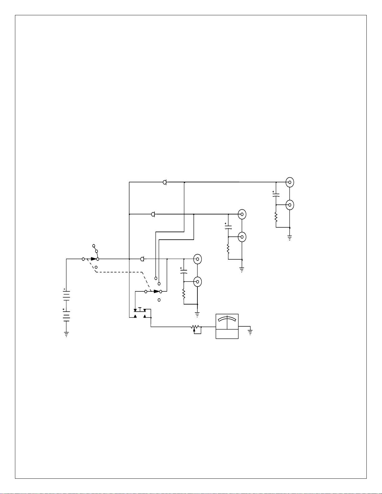
Description (Figure 1)
Model PS03 utilizes three 2 mA current regulating JFET diodes to supply the
sensor drive current to up to 3 sensors. The metering circuit draws only 25µA at
mid-scale (its normal operating level). With this low current drain, the battery life,
starting out with a fresh pair of alkaline batteries, will be about 80 hours. Figure 1
is a schematic diagram of one channel of Model PS03. The voltmeter normally
monitors the sensor bias voltage which is nominally about +10 Volts DC. Consult
the specification sheet for your particular sensor to verify the actual bias voltages
since some sensors have various other bias voltages.
Section I
Overview

MNX10010 / Rev B
4/11/2008 3
The ‘BATT TEST’ switch momentarily connects the meter directly across the
battery terminals when depressed, to allow the user to check the actual battery
voltage during operation. This procedure will not disturb the test in progress.
The dynamic signal from the sensor is superimposed upon the bias voltage and
appears at the “Sensor’ jack. This signal is de-coupled from the DC bias by the
10µf coupling capacitor and connected to the ‘Output’ jack.
It can be seen, by examination of Figure. 1, that the dynamic signal may also be
read by coupling to the ‘Sensor’ jack as well. However, if this is attempted, a
means of dealing with the +10 Volt DC offset must be considered.
This type of connection can be useful when it is desirable to direct couple the
readout to the sensor rather than to AC couple. More on this topic later.
1 MEG
1 MEG
10 µF
10 µF
OUTPUT
CHAN1
SENSOR
CHAN1
SENSOR
CHAN2
OUTPUT
CHAN2
SENSOR
CHAN3
OUTPUT
CHAN3
OFF
CH1
CH2
CH3
S1-B
+
FRONTPANEL
ROTARYSWITCH
10µF
2 mA CC
DIODE
2 mA CC
DIODE
2 mA CC
DIODE
+ 18VOLTS
1 MEG
OFF
MONITOR
VOLTMETER
BATTTEST
PUSHBUTTON
Figure 1. Schematic Diagram, PS03

MNX10010 / Rev B
4/11/2008 4
MODEL PS03 3-CHANNEL
CURRENT SOURCE POWER UNIT,
BATTERY POWERED
1Any type of transistor radio 9-Volt battery may be use to power the PS03.
However, longest battery life will be obtained by use of high grade alkaline type
batteries.
The PS03 is a bench top unit that requires no special installation instructions.
SPECIFICATION VALUE UNITS
SENSOR SUPPLY CURRENT, FIXED, NOM. 2.0 mA
COMPLIANCE VOLTAGE +18 VDC
VOLTAGE GAIN UNITY
COUPLING TIME CONSTANT INTO 10 MEGOHM LOAD 10 SEC
COUPLING TIME CONSTANT INTO 1 MEGOHM LOAD 5SEC
LOW FREQUENCY -3db FREQ., 10 MEGOHM LOAD 0.016 Hz
LOW FREQUENCY -3db FREQ., 1 MEGOHM LOAD .032 Hz
HIGH FREQUENCY RESPONSE DETERMINED BY SENSOR,
CABLE LENGTH AND SIGNAL
LEVEL
COUPLING CAPACITOR, NOM. 10 µF
PULLDOWN RESISTOR 1.0 MEGOHMS
MONITOR VOLTMETER RANGE, F.S. 20 VDC
ELECTRICAL NOISE, WIDEBAND 60 µV, RMS
SENSOR CONNECTOR BNC JACK
OUTPUT CONNECTOR BNC JACK
POWER SOURCE 19 VOLT BATTERIES (2) ea.
BATTERY LIFE, TYP. 40 HOURS
SIZE (H x W x D) 2.5 x 5.2 x 3.3 INCHES
WEIGHT 12 OUNCES
Section II
Installation
Table 1. Specifications

MNX10010 / Rev B
4/11/2008 5
Operating Procedure
To operate the PS03 with a sensor, connect the sensor cable to the BNC
‘Sensor’ jack on the channel one of the PS03 using the appropriate cable and or
adaptor. (Refer to Figure 2.)
Connect the ‘Output’ jack for channel one to the input of the readout instrument
(oscilloscope, voltmeter, recorder, etc.) using an appropriate cable. The BNC
output jack on the PS03 eliminates the need for cable adaptors for the readout
connection.
Move the rotary channel select switch on the front panel to the channel 1 position
which turns the power on and selects channel 1 for monitoring on the front panel
voltmeter. Wait a few seconds for the coupling capacitor(s) to fully charge. The
meter may indicate a slow drift while the capacitor is charging.
When conditions stabilize, observe the front panel meter. Normal operation of the
sensor is indicated by a mid-scale reading on this meter. The normal mode of
operation for most sensors is in the “Normal’ area of the meter scale.
Depress the ‘Batt Test’ pushbutton switch and observe the battery voltage. The
meter should read to the right of the ‘Batt OK’ line at the right hand end of the
meter scale if the batteries are fresh. When the battery test function yields a
reading well below the Batt OK line, it is time to replace the batteries. While the
sensor will continue to function even with low batteries, clipping of the signal may
occur on the top (positive) side of the dynamic signal if the sensor signal plus the
sensor bias approaches the battery voltage.
The system is now ready to operate. Connect two more sensors if desired and
follow the same procedure as for channel 1.
Section III
Operation
Oscilloscope or other
readout instrument
NOTE: To prolong battery life, remember to switch power off when the
system is not in use.
Typical Sensor
Figure 2. Systems Interconnect
Model PS03

MNX10010 / Rev B
4/11/2008 6
COUPLING TIME CONSTANT AND LOW FREQUENCY
RESPONSE
The low frequency capability of a piezoelectric measurement system may be
limited by several factors about which the average user of such systems may not
be aware.
The specifications each sensor will delineate the discharge time constant which
controls the basic low frequency response of that sensor. However, the power
unit and the readout may also play a part in this specification and may, in many
cases, be the limiting factor rather than the sensor itself.
The low frequency response of any AC coupled system is limited by the coupling
time constant (TC) of the composite measurement system. The coupling
capacitor and the 1 megohm ‘pulldown’ resistor in each channel of the PS03, in
parallel with the DC input resistance of the readout instrument constitute a first
order high pass filter.
The TC of this filter is the product of the 10µF capacitor and the parallel
combination of the 1 megohm pulldown resistor and the input resistance of the
readout instrument.
The relationship between the coupling TC and the lower -3db frequency is:
If the readout instrument is of the order of 10 megohms, it may be ignored. The
TC is then 10µF x 1 megohms = 10 seconds. The lower -3db frequency is then:
If the readout instrument input resistance is 1 megohm, the parallel combination
of the pulldown resistor and the input resistance is 500k ohms. The TC is then
10µF x 500,000 or 1 second. The lower -3db frequency is then:
Eq 1. 0.16
f
-3db = --------------
TC
Where: TC is the
p
roduct of R and C
,
in Seconds
Eq 2. 0.16
f
-3db = ------------ = 0.016 Hz
10
Eq 3. 0.16
f
-3db = ----------- = .16 Hz.
10

MNX10010 / Rev B
4/11/2008 7
The importance of this illustration is to show that the sensor itself may not be the
deciding factor in low frequency response and to stress the importance of the
input impedance of the readout instrument on the low frequency response of AC
coupled sensor systems.
OPTIONAL DIRECT COUPLED CONNECTION FOR QUASI-
STATIC MEASUREMENTS
For some types of measurements such as when using dead weight testers to
calibrate pressure sensors or when making long term measurements with force
sensors with long TC’s, it is desirable to direct couple to the sensor instead of AC
coupling as through the ‘Output’ jack of the PS03.
To avoid the low frequency limitations as described in the previous section, it is
possible, with some precautions, to use the ‘Sensor’ jack to measure the sensor
signal, direct coupled instead of AC coupled through the ‘Output’ jack.
To do this, a BNC ‘T’ is connected to the ‘Sensor’ jack with one arm of the T
connected to the sensor and the other arm connected to the readout. (Refer to
Figure 3 above). The problem with this arrangement is that the readout must
have the capability of ‘nulling out’ the approximate +10 Volt DC offset created by
the sensor bias. Most readout instruments will not have this capability.
A better solution is to use a power unit which has a direct coupling option such as
the CTC PS06 or PS02. These line powered current sources feature a summing
amplifier which sums the sensor signal with a variable DC voltage and which
nulls the sensor bias precisely to zero with no coupling capacitors, i.e., direct
coupled to the output jack. With this power unit, the only limiting factor in the low
frequency or quasi-static response of the measurement system is the discharge
TC of the sensor itself.
Oscilloscope or
other readout
instrument
Typical Sensor
Model PS03
BNC “T”
Connecto
r
Figure 3. Optional Direct Coupled Connections

MNX10010 / Rev B
4/11/2008 8
HIGH FREQUENCY RESPONSE
The high frequency response of any piezoelectric system is determined by a
number of factors. These are:
1. The response characteristics of the sensor itself,
2. The length and type of cable between the sensor and the power unit,
3. The length and type of cable from the sensor to the readout, (in
unbuffered units such as the 4103B),
4. The amplitude of the sensor signal, and,
5. The level of drive current to the sensor.
With the PS03, the user has no choice of drive current settings since the sensor
drive current is fixed at approximately 2 mA.
This amount of current should be sufficient to drive most sensors (except for
some of the high frequency pressure sensors) to their full frequency range driving
100 ft. of combined input and output cable.
Experimentation is the only sure way to determine the effect of these various
parameters on the high frequency response of the measurement system.
Figure 4. PS03 Power Supply Diagram

MNX10010 / Rev B
4/11/2008 9
CHANGING THE BATTERIES
When the ‘BATT TEST’ switch is depressed (or when the sensor is
disconnected), the meter will indicate the battery voltage. When this reading
drops below the ‘BATT OK’ mark on the meter dial, it is time to replace the
batteries.
NOTE: Under some circumstances, it is possible to continue to use the
PS03 even with low batteries as in emergencies. If the measurement level is
low and there is no danger of clipping the signal in the positive direction,
then it is OK to use the system. As an example, if the battery voltage drops
to 14 Volts and the sensor bias is +10.5 Volts, the available signal swing is
14 - 10.5 = 3.5 Volts. If 3.5 Volts is adequate range for the measurement, the
measurement will be valid.
To change the batteries, proceed as follows:
1. Remove the two screws at the bottom of the unit and separate the two
halves of the case. Remove the bottom half of the case.
2. Carefully unsnap the connectors from the battery terminals using care not
to overstress the wires to the terminals.
3. Remove the batteries from the battery clips and replace both with a good
brand of 9V dry cell such as Duracell © MN1604, Eveready Energizer ©
alkaline no. 522, or equivalent. Before installing the batteries, make sure
that they will fit into the clips. Some brands of battery may be oversize and
these should not be used since there may not be adequate room for them
in the PS03.
4. Re-attach the battery terminals and re-assemble the unit and outer case.
Use caution not to over tighten the front panel retaining screws to avoid
stripping the plastic threads in the case.
Section IV
Maintenance

MNX10010 / Rev B
4/11/2008 10
General
Aside from battery replacement, there is no routine maintenance required for the
PS03.
Should the meter require re-zeroing, place the unit on a level table, face up with
the power off, and adjust the zero adjust screw located directly below the meter
face.
It is not likely that the meter should need recalibration but should this become
necessary, a potentiometer is located inside the unit mounted on the circuit
board. This pot sets the full scale reading of the meter. First measure the battery
voltage with a DVM connected across the appropriate battery terminals (the
batteries are in series) then set the meter scale to match by adjusting the
potentiometer.
The connectors may be cleaned with a soft brush dipped in a solvent which is
friendly to the atmosphere and to the plastic face of the meter and the outer case
of the instrument. Avoid solvents such as methylene chloride and acetone which
will attack the meter face and other plastic parts.
Should the PS03 develop a problem, contact the factory Customer Service
Department for help in trouble shooting or for instructions in returning the unit to
the factory for evaluation. At this time, a Returned Material Authorization (RMA)
number will be assigned to help track the unit through the repair process, should
it be necessary to return the unit to the factory.
Warranty
If any PRO product should ever fail, we will repair or replace it at no charge, as
long as the product was not subjected to misuse, natural disasters, improper
installation or modification which caused the defect.
CONTACT INFORMATION:
Connection Technology Center, Inc (CTC)
7939 Rae Blvd.
Victor, NY 14564
1-800-999-5290 (US & Canada) 1-585-924-5900 (International)
Table of contents