Pro2 HDMIIPLR HDMI Over CAT6 Extender User manual
www.pro2.com.au
HDMI Over CAT6 with IR
HDMIIPLR
User Manual
Transmitter
Receiver

Notice
PRO2 reserves the right to make changes in the hardware, packaging and
any accompanying documentation without prior written notice.
© 2012 PRO2, All Rights Reserved.
All trademarks are the property of their respective companies.
Rev × A

CONTENTS
1. Introduction
2. Features
3. Transmitter Unit Panel Layout
4. Transmitter Unit Panel Descriptions
5. Receiver Unit Panel Layout
6. Receiver Unit Panel Descriptions
7. Remote Control Panel Layout & Descriptions
8. Connecting and Operating HDMI Over CAT6 Extender with IR
9. Specifications
10. Warranty
11. Compliance
12. Appendix A

INTRODUCTION
The HDMIIPLR HDMI Over CAT6 Extender with IR-Transmitter &
Receiver
The HDMIIPLR HDMI Over CAT6 Ethernet Extender with IR sends
HDMI signals over just one 100Ohm CAT6 cable -- up to 330 feet away.
The HDMIIPLR HDMI Over CAT6 Extender supports HDMI 1.3 with
Full HD 1080p resolution. DVI-D Computer video can also be transmitted
with a DVI-to-HDMI cable
By using standard and widely available 100Ohm CAT6 cables, the
HDMIIPLR HDMI Over CAT6 Extender makes HDMI signal extensions
easier than heavy and expensive copper cable and more robust than
optical fiber.
How it connects
The HDMIIPLR HDMI Over CAT6 Ethernet Extender system consists of
a Transmitter and a Receiver. The HDMI source (set-top box, DVD player,
or gaming console) connects to the Transmitter box. The Receiver box
connects to the HDTV display in the same way -- up to 330 feet away.
One 100Ohm CAT6 cables link the Transmitter and Receiver. Power is
applied to the Transmitter and Receiver with 5V DC power supply.
HDMI picture emerges on the HDTV display.
Note:The HDMIIPLR HDMI Over CAT6 Extender is HDCP 2.0 compliant.

FEATURES
Flexible extension of high-bandwidth HDMI 1.3
Audio and video are transmitted digitally over the 100Ohm CAT6 cable
for lower signal loss
Single Link Range: 1080p/60 and 1920x1200.
Compliant with HDMI 1.3, HDCP 2.0 and DVI1.1 standards
Supports digital video formats in 480p , 720p and 1080p
Supports PCM 2 Ch audio
Supports IR Pass-through function to control HDMI source devices
(set-top box, DVD player and Blue ray DVD Player) from Receiver by
its IR extender input
It can control source channel via IR remote control provided
Package Includes
(1) HDMIIPLR-TX HDMI Over CAT6 Ethernet Transmitter
(2) HDMIIPLR-RX HDMI Over CAT6 Ethernet Receiver
(3) IR Receiver Cable
(4) IR Remote control
(5) 2x 5V DC Power Supplies for Transmitter and Receiver
(6) User Manual
Optional Items:
If you need the following items, please let us know and we will quote for
you.
(1) HDMI Cable (3 feet / 6 feet / 10 feet)
(2) Mounted Ear & Screws
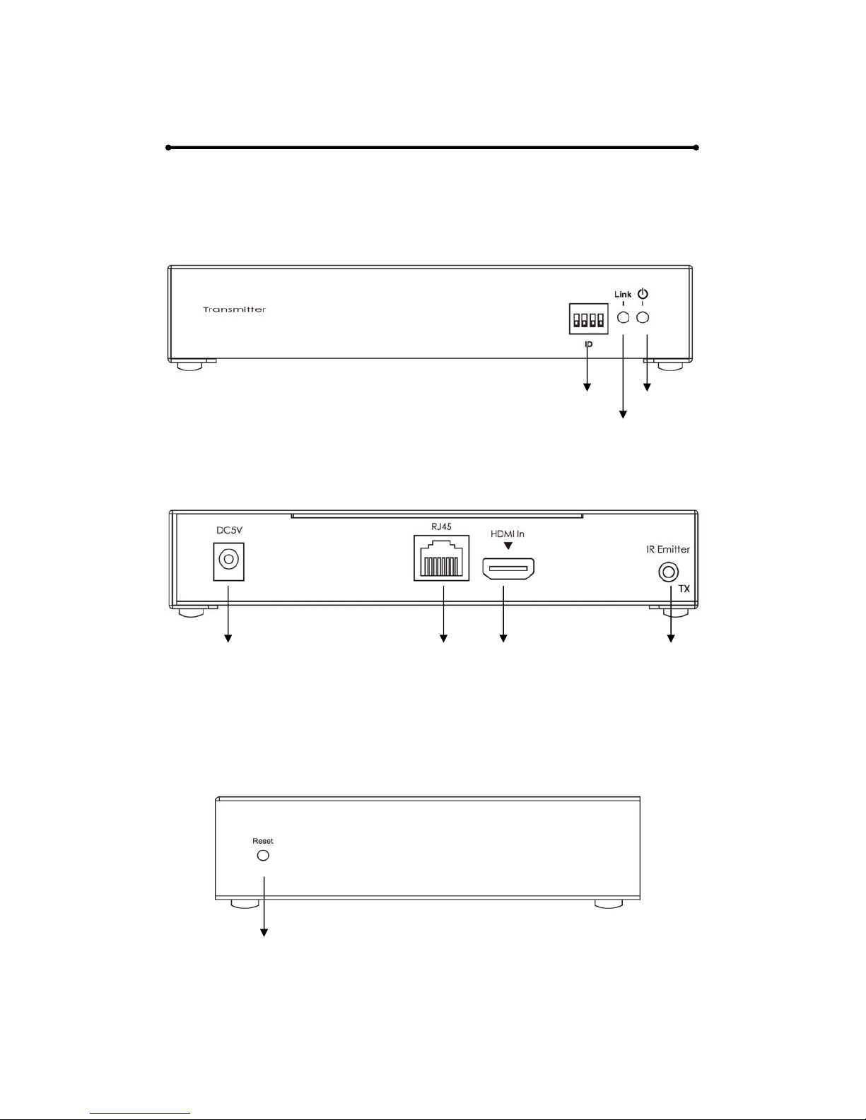
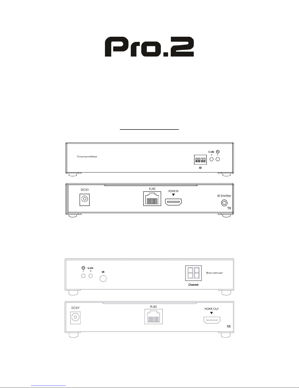
TRANSMITTER UNIT PANEL LAYOUT
Front Panel
Back Panel
Side Panel
Power Input port RJ45 Port HDMI Input port IR Emitter
DipSwitch PowerLED
LinkLED

TRANSMITTER UNIT PANEL DESCRIPTIONS
1. Power LED
This LED indicator will activate once the included 5V DC power adapter
has been properly connected between the Transmitter unit and an open
wall power socket.
2. Link LED
This LED indicator will activate once Cat 6. cable has been properly
connected between the Transmitter unit and Receiver unit.
3. Dip Switch
Dip switch is designed to define the source channel. Different
combination of dip switch refers different source channel. User can
change the combination of dip switch in order to define source. There
are 16 combinations for dip switch, please refer to Appendix A.
4. Power Input Port
Connect the 5V DC power supply to this input port.
5. RJ45 Port
Connect a 100Ohm CAT6 cable between this output port and the RJ45
input port from Receiver unit
6. HDMI Input port
Connect one HDMI cable between this port and HDMI output port of
the source device (DVD, Set-top box, blue-ray DVD)
7. IR Emitter
Connect an IR Emitter Cable to this IR port and stick IR emitter module
on the IR receiver zone of HDMI source (set-top box, DVD player and
Blue ray DVD Player).
8. Reset
Please press this button once it has connecting problem.
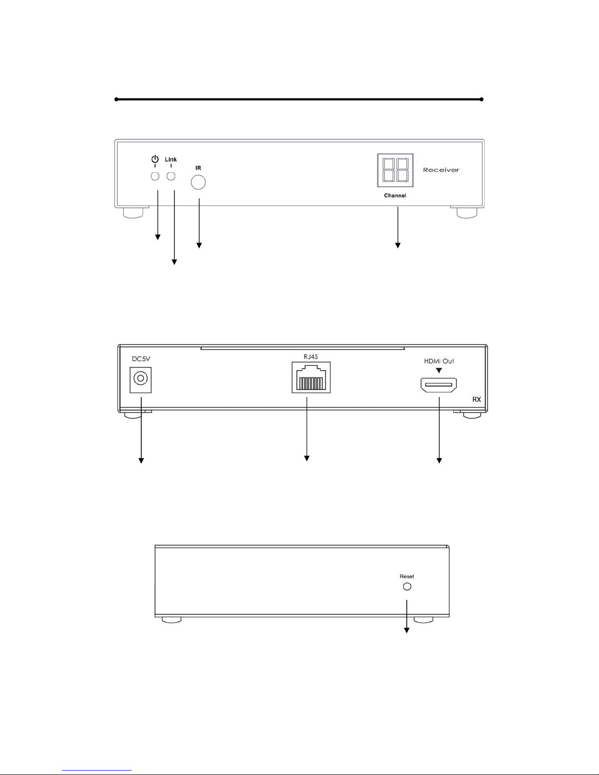
RECEIVER UNIT PANEL LAYOUT
Front Panel
Back Panel
Side Panel
PowerLED IRExtender LEDDisplay
LinkLED
Power Input port RJ45 Port HDMI output port
Reset

RECEIVER UNIT PANEL DESCRIPTIONS
1. Power LED
This LED indicator will activate once the included 5V DC power adapter
has been properly connected between the Receiver unit and an open
wall power socket.
2. Link LED
This LED indicator will activate once Cat 6. cable has been properly
connected between the Transmitter unit and Receiver unit.
3. IR Extender
Please connect one IR Extender cable to this port. Once IR emitter cable
has been connected between Transmitter and the source device, the
source device can be controlled at the Receiver end by its IR remote
controller.
4. LED Display
The LED Display is designed to identify which source channel the
receiver should display. User can select source channel via remote
control. Please refer to Appendix A for related link diagram.
5. Power Input Port
Connect 5V DC power supply to this input port.
6. RJ45 Port
Connect a 100Ohm CAT6 cable between this input port and the RJ45
output port from Transmitter unit.
7. HDMI output port
Connect the one HDMI cable between this output port and HDMI input
port of the HDTV display.
8. Reset
Please press this button once it has connecting problem.

REMOTE CONTROL
PANEL LAYOUT & DISCRIPTIONS
Front Panel
1. Downward Selection Button
This button allows user to switch source channel downwardly (from
source 16 to source 1). By long pressing the button, source will be
changed in a short time.
2. Upward Selection Button
This button allows user to switch source channel upwardly (from source
1 to source 16). By long pressing the button, source will be changed in a
short time.
Press to switch
source channel
downward
Press to switch
source channel
upward
CONNECTING AND OPERATING
How to Connect the HDMIIPLR HDMI Over CAT6 Extender
One Source to One Display Function
1. Connect one HDMI Cable between the HDMI output port of source
device and the HDMI input port of Transmitter unit
2. Connect one HDMI Cable between the HDMI input port of display
device and the HDMI output port of Receiver unit.
3. Connect one 100Ohm CAT6 cable between the RJ45 port of
Transmitter unit and RJ45 port of Receiver unit.
4. Connect 5V DC power supplies to both Transmitter and Receiver unit.
5. Power on the output device first and then the source device.
6. Use remote control to select the related channel dip switch has set up
on the transmitter side. Please refer to Appendix A for the link diagram.
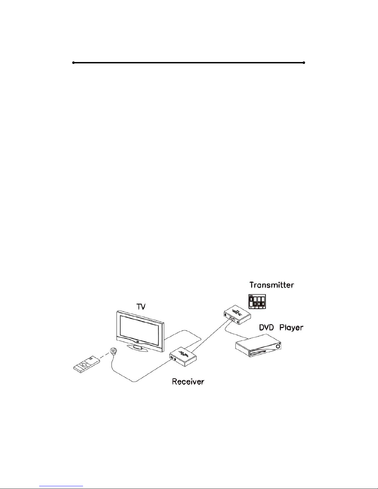
Note:
1. IR Function is able to receive signal from remote control of your
DVD player and remote control given along with our Receiver unit.
Please refer to following diagram:

CONNECTING AND OPERATING
How to Connect the HDMIIPLR HDMI Over CAT6 Extender
One Source to Many Displays Function
2. Connect one HDMI Cable between the HDMI output port of source
device and the HDMI input port of Transmitter unit
3. Connect one 100Ohm CAT6 cable between the RJ45 port of transmitter
and input port of Gigabit Ethernet switch hub.
4. Connect one 100Ohm CAT6 cable between the output port of each
Gigabit Ethernet switch hub and RJ45 port of Receiver unit.
5. Connect 5V DC power supplies to both Transmitter and Receiver unit.
6. Power on the output device first and then the source device.
7. Use remote control to select the related channel dip switch has set up
on the transmitter side for each receiver. Please refer to Appendix A for
the link diagram.
Note:
1. IR Function is able to receive signal from remote control of your
DVD player and remote control given along with our Receiver unit.
2. As our Transmitter unit can support over 200 IP address for
different receiver unit, it can connect up to 200 pcs Receiver units.
3. Please note that the Ethernet switch hub should be Gigabit Ethernet
switch hub.
Please refer to following diagram:

CONNECTING AND OPERATING
How to Connect the HDMIIPLR HDMI Over CAT6 Extender
Many Sources to Many Displays Function
1. Connect one HDMI Cable between the HDMI output port of source
device and the HDMI input port of Transmitter unit.
2. Connect one HDMI Cable between the HDMI input port of display and
the HDMI output port of Receiver unit.
3. Connect one 100Ohm CAT6 cable between the RJ45 of each
Transmitter unit and RJ45 port of Gigabit Ethernet switch hub.
4. Connect one 100Ohm CAT6 cable between each RJ45 port of Gigabit
Ethernet switch hub to RJ45 port of Receiver unit. User can select
source channel by setting up dip switch on each transmitter unit. And
select display source for Receiver units via one remote control.
5. Connect 5V DC power supplies to all Transmitter units and
Receiver units.
6. Use remote control to select the channel of the desired transmitter to
change sources.
Note.
1. IR Function is able to receive signal from remote control of your
DVD player and remote control given along with our Receiver unit.
2. As our Transmitter unit can support over 200 IP address for
different receiver unit, it can connect up to 200 pcs Receiver units.
3. As each Transmitter has 4 ports of dip switch, it is able to create 16
combinations to define 16 source channels. Therefore, user can
connect at most 16 Transmitter to the system. See Appendix A for
selecting Transmitter channel.
4. Please note that the Ethernet switch hub should be Gigabit Ethernet
switch hub and has IGMP function.
Please refer to following diagram on the next page:


SPECIFICATIONS
Video Amplifier Bandwidth .............................................................. 225 MHz
Video Output ………………………......... 1080p/60 and 1920x1200 max. res
Input DDC Signal .......... 5 Volts p-p (TTL); Input Video Signal: 1.2 Volts p-p
HDMI Connector .......................................................... Type A, 19 Pin Female
Link Connector ............................................................................ RJ45 Shielded
Power Supply ............................. 5V DC / Power Consumption: 5 Watts max.
Operating Temperature ..................................................................... 0°C - 40°C
PERFORMANCE
HDTV Resolutions 480p, 720p, 1080i, 1080p
Standard TV Resolution 480i
Maximum Cable Range HDMI Input: 15 feet Max, Outputs: 330 feet
Max (Cat6 Cable)
Video Bandwidth 6.95Gbps
Input Video Signal 1.2 Volts P-P
Input DDC Signal 5.0 Volts P-P
I/O CONNECTORS
Transmitter
Inputs 1 HDMI-A 19PIN Socket
Outputs 1 RJ45 Jack
1 3.5mm Jack-IR Emitter
Receiver
Inputs 1 RJ45 Jack
1 IR Receiver Module
Outputs 1 HDMI-A 19PIN Socket

MECHNICAL
Transmitter
Dimensions (H-W-D) 162.3x114.85x30mm
Weight 0.5kg
Receiver
Dimensions (H-W-D) 162.3x114.85x30mm
Weight 0.5kg
WARRANTY
Limited Warranty 1 Year Parts and Labor
ENVIRONMENTAL
Operating Temperature +0 to +40° C (+32° to 104° F)
Operating Humidity 10% to 85% (Non-condensing)
Storage Temperature -20° to +60° (+20° to +140° F)
Storage Humidity 10% to 85% (Non-condensing)
REMOTE CONTROL
Infrared IR Remote (Front)
POWER REQUIREMENTS
Power Consumption 10 Watts (Max.)
SAFETY
Certificate FCC, CE, RoHS
Power Adapter UL, CE, CSA, CEC, RoHS
ACCESSORIES
AC Power Adapter X 1 US, UK or Euro Type
Sender Instruction Manual X 1

WARRANTY
LIMITED WARRANTY – With the exceptions noted in the next paragraph,
PRO2 warrants the original purchaser that the equipment it manufactures
or sells will be free from defects in materials and workmanship for a period
of one year from the date of purchase. Should this product, in PRO2’s
opinion, prove defective within this warranty period, PRO2, at its option,
will repair or replace this product without charge. Any defective parts
replaced become the property of PRO2. This warranty does not apply to
those products which have been damaged due to accident, unauthorized
alterations, improper repair, modifications, inadequate maintenance and
care, or use in any manner for which the product was not originally
intended.
Items integrated into PRO2 products that are made by other manufacturers,
notably computer hard drives and liquid crystal display panels, are limited
to the term of the warranty offered by the respective manufacturers. Such
specific warranties are available upon request to PRO2.
PRO2 makes no other representation of warranty as to fitness for the
purpose or merchantability or otherwise in respect of any of the products
sold. The liability of PRO2 with respect to any defective products will be
limited to the repair or replacement of such products. In no event shall
PRO2 be responsible or liable for any damage arising from the use of such
defective products whether such damages be direct, indirect, consequential
or otherwise, and whether such damages are incurred by the reseller,
end-user or any third party.

COMPLIANCE
The HDMIIPLR HDMI Over CAT6 Ethernet Extender have been tested for
compliance with appropriate FCC and CE rules and regulations and are also
RoHS compliant.
The Power has been tested for compliance with UL, CE and CSA rules and
regulations and is also RoHS compliant.

Appendix A Setting Transmitter Channel
There are 16 combinations for Dip Switch, please refer to the following
table, which defines 16 source channels for the system.
RX TX/DIPSW
LED ON OFF
No. 1 2 3 4
1.
2.
3.
4.
5.
6.
7.
8.
9.
10.
11.
12.
13.
14.
15.
16.
This manual suits for next models
1
Table of contents
Other Pro2 Extender manuals


