ProActiv NJ1 el. Parts list manual

NJ1 el. & FREAK el. compact bike usage instructions
0
Usage instructions
Service booklet
NJ1 el. compact bike
FREAK el. compact bike

NJ1 el. & FREAK el. compact bike usage instructions
1
Contents
1 Preface ............................................................................................................................................... 4
2 Legend ................................................................................................................................................ 4
3 Conformity/other information .............................................................................................................. 4
3.1 Classification ............................................................................................................................... 4
3.2 Conformity................................................................................................................................... 4
3.3 Manufacturer ............................................................................................................................... 4
4 Scope of delivery and testing the product on receipt ......................................................................... 4
5 Introduction ......................................................................................................................................... 5
6 Purpose and indication ....................................................................................................................... 5
7 Proper use .......................................................................................................................................... 6
8 Technical specifications ..................................................................................................................... 7
8.1 Drive system ............................................................................................................................... 7
8.1.1 General instructions ....................................................................................................... 7
8.1.2 Travel range ................................................................................................................... 7
8.1.3 Speed ............................................................................................................................. 7
8.1.4 Maximum permitted speed ............................................................................................ 7
8.2 Climbing power ........................................................................................................................... 7
8.3 Product weight ............................................................................................................................ 8
8.4 Load weight................................................................................................................................. 8
8.5 Ground clearance & turning circle .............................................................................................. 8
8.6 Basic equipment and dimensions ............................................................................................... 8
8.7 Service life .................................................................................................................................. 8
9 Rating plate & markings on the product ............................................................................................. 8
10 Commissioning and handover ............................................................................................................ 9
11 Introduction to the product and the surroundings ............................................................................... 9
12 Safety instructions – prior to driving/use .......................................................................................... 10
13 Safety instructions – while driving/using .......................................................................................... 10
14 Safety instructions regarding obstacles ........................................................................................... 12
15 Safety instructions regarding dangerous locations and dangerous situations ................................. 12
16 Safety instructions – after driving/use .............................................................................................. 13
17 Functional elements ......................................................................................................................... 13
17.1 Bottom bracket support and crank ................................................................................... 13
17.1.1 Seating position ........................................................................................................... 13
17.1.2 Bottom bracket position ............................................................................................... 14
17.1.3 Crank length and grip width ......................................................................................... 15
17.2 Grips ......................................................................................................................................... 15

NJ1 el. & FREAK el. compact bike usage instructions
2
17.3 Gear shift .................................................................................................................................. 15
17.3.1 Derailleur ...................................................................................................................... 15
17.3.2 Charging the battery for Shimano electronic gearshifts ............................................... 17
17.3.3 Bottom bracket gearshift .............................................................................................. 17
17.4 Brakes ....................................................................................................................................... 18
17.4.1 Rim and disc brakes .................................................................................................... 18
17.4.2 Parking brake ............................................................................................................... 19
17.4.3 PRO ACTIV back-pedalling brake & crank release function ....................................... 19
17.5 Rechargeable battery pack ....................................................................................................... 20
17.5.1 General instructions ..................................................................................................... 20
17.5.2 Change-over device for double rechargeable batteries ............................................... 20
17.6 Drive system ............................................................................................................................. 21
17.6.1 Switching on and off..................................................................................................... 21
17.6.2 Attaching and removing the display ............................................................................. 21
17.7 Lights ........................................................................................................................................ 22
17.8 Bell ............................................................................................................................................ 22
17.9 Manufacturer instructions ......................................................................................................... 23
18 Backrest ............................................................................................................................................ 23
18.1 Angle adjustment of the backrest ............................................................................................. 23
18.2 Longitudinal positioning of the backrest ........................................................................... 24
19 Seat system ...................................................................................................................................... 24
20 Neck rest .......................................................................................................................................... 25
20.1 Neck rest height adjustment ............................................................................................. 25
20.2 Neck rest angle adjustment ...................................................................................................... 25
21 Collision guard .................................................................................................................................. 26
21.1 Collision guard mount ............................................................................................................... 26
21.2 Mounting the collision guard ..................................................................................................... 26
21.3 Adjusting the length of the collision guard ....................................................................... 27
22 Wheels .............................................................................................................................................. 27
22.1 Removing and attaching the running wheels ............................................................................ 27
22.2 Checking and adjusting the wheel tracking of the running wheels .................................. 27
22.3 Tyre pressure ............................................................................................................................ 29
23 Adaptation and decoupling the drive unit ......................................................................................... 30
23.1 Safety instructions .................................................................................................................... 30
23.2 Terminology .............................................................................................................................. 30
23.3 Adapting the drive unit .............................................................................................................. 30

NJ1 el. & FREAK el. compact bike usage instructions
3
23.4 Decoupling the drive unit .......................................................................................................... 32
24 Storage ............................................................................................................................................. 33
25 Transport .......................................................................................................................................... 33
25.1 Securing handling of the product .............................................................................................. 33
25.2 Passenger transport in vehicles ............................................................................................... 33
25.3 Securing the product in a vehicle (without a person) ............................................................... 33
25.4 Transport in aircrafts ................................................................................................................. 34
26 Malfunctions ..................................................................................................................................... 34
27 Cleaning and care ............................................................................................................................ 34
28 Maintenance ..................................................................................................................................... 35
28.1 General instructions .................................................................................................................. 35
28.2 Service schedules ..................................................................................................................... 35
28.3 Proof of maintenance ................................................................................................................ 36
29 Disposal and recycling ..................................................................................................................... 36
30 Re-use .............................................................................................................................................. 37
31 Warranty ........................................................................................................................................... 37
32 Liability .............................................................................................................................................. 38
33 Appendix: Tightening torques, securing details and tools ................................................................ 39
34 Appendix: Medical product passport/record of training .................................................................... 40
35 Appendix: Hand-over certificate ....................................................................................................... 41
35.1 Required compliance criteria to authorise use ......................................................................... 41
35.2 Check list for training the user .................................................................................................. 42
36 Appendix: Inspection lists ................................................................................................................. 43
The following instructions are intended for and may only be carried out by the rehabilita-
tion specialist dealer or PRO ACTIV.
This document is available in PDF format at
www.proactiv-gmbh.com for visually impaired people. Using the zoom function, the font
can be increased as desired.

NJ1 el. & FREAK el. compact bike usage instructions
4
1 Preface
Dear Customer,
Congratulations on purchasing your new
PRO ACTIV product. You have bought a quali-
ty product that has been specially customised
to meet your requirements. We have put to-
gether some instructions about its proper and
safe use in the following document. Please
read these instructions before using the prod-
uct.
The standard components are explained in
these usage instructions. If you have individual
solutions or non-standard components on your
product, your rehabilitation specialist dealer or
PRO ACTIV would be happy to deal with any
questions you may have about using it.
The only difference between the compact bikes
NJ1 el. & FREAK el. is the design of the frame
(or in the frame sizes that can be selected).
The operating instructions are therefore identi-
cal.
You can always download the latest version of
the usage instructions as a PDF document in
our download area at www.proactiv-gmbh.com.
If you have any further questions about this or
any of our other products, we would be glad to
be at your disposal.
Enjoy your trips and the best possible mobility.
Your PRO ACTIV team
2 Legend
The symbols used in these usage instructions
have the following meanings:
Manufacturer
Warnings and safety instructions
Serial number
3 Conformity/other information
3.1 Classification
The NJ1 el. & FREAK el. compact bikes (re-
ferred to as the "product" below) are classified
as class I products.
3.2 Conformity
As the manufacturer, PRO ACTIV
Reha-Technik GmbH declares that
the respective product is a class I product and
meets the requirements of the EU Medical
Devices Directive (2017/745).
If the product is adapted in a manner which
has not been agreed by PRO ACTIV Reha-
Technik GmbH, this declaration becomes void.
3.3 Manufacturer
PRO ACTIV Reha-Technik GmbH
Im Hofstätt 11
D-72359 Dotternhausen
Phone +49 7427 9480-0
Fax +49 7427 9480-7025
e-mail: info@proactiv-gmbh.de
web: www.proactiv-gmbh.com
4 Scope of delivery and testing
the product on receipt
The scope of delivery includes the product
configured in accordance with the order, re-
chargeable battery/batteries, display/operating
console, mains power charger, usage instruc-
tions including record of training/hand-over
certificate and inspection lists. You can view
the basic equipment in chapter "Technical
specifications". As per your order, the product
is equipped with additional recommended ac-
cessories, such as e.g., lighting and hip strap.
Please check that the delivery is complete after
you have received your product.
The product is tested to ensure it is completely
functional before shipping and packed in spe-
cial boxes.
However, please check the product immediate-
ly upon receipt, preferably in the presence of
the freight company, for any damage which

NJ1 el. & FREAK el. compact bike usage instructions
5
may have occurred in transit. If you are of the
opinion that damage has occurred during
transit, please do the following:
1. Record a statement of facts in the pres-
ence of the freight company - photo docu-
mentation of the packaged product and the
unpacked product with detailed images of
product damage
2. Preparation of a declaration of assignment
- you assign all claims from this damage to
the freight company.
3. Statement of facts/photo documentation,
delivery note, and declaration of assign-
ment are sent to PRO ACTIV.
Failing to observe these instructions, or report-
ing damage after acceptance, means that the
damage cannot be acknowledged.
PRO ACTIV will subsequently review the dam-
age and discuss the further procedure with you
(shipment of replacement parts, returning the
product to PRO ACTIV for a complete repair,
etc.).
5 Introduction
Before starting your first journey, familiarise
yourself with these usage instructions, paying
particular attention to all of the safety infor-
mation and hazard warnings contained in
them.
Allow your therapists and doctors to advise
you, your carers, and assistants on how to use
the product and what you are safe to do with
the product based on your current ability.
Under no circumstances should you do
anything with or in the product which you have
not learnt to do and have not mastered.
You, your carers, and assistants should also
seek advice from your therapists and doctors
as well as the rehabilitation specialist dealer
about the use and settings of your product as
well as all the safety accessories available
(e.g., hip belt).
You should always heed the advice pro-
vided by doctors, therapists and the rehabilita-
tion specialist dealer on the necessary safety
accessories.
If you are not sure how to handle the
product or if technical faults occur, please con-
tact your rehabilitation specialist dealer or
PRO ACTIV before using it.
The control software is programmed at
the factory to ensure that the legal require-
ments for a pedelec drive are met. If changing
the software, it must be ensured that these
requirements are still met.
Never leave the product unattended, ei-
ther when it is switched on or switched off. If
this cannot be avoided, removing the re-
chargeable battery/batteries and the display
can help prevent unauthorised use.
Secure the product against unauthorised
use and theft.
When combining your product with
equipment made by other manufacturers,
make sure that the individual components and
the unit made up of them still work appropriate-
ly. You can get information on the suitability of
a combination from the manufacturer of the
third-party components or from your rehabilita-
tion specialist retailer.
The product contains small parts that may
pose a choking hazard for children.
6 Purpose and indication
This product offers persons who have difficulty
walking or cannot walk the option of replacing
walking by riding a muscle-powered compact
bike with electric assistance to a technically
feasible extent, with the aim of maintaining or
increasing the active user’s independent mobil-
ity to the greatest possible extent. The electric
drive system supports the active cranking mo-
tion of the arms by the user, therefore making
locomotion easier.
Indications: Walking impediment or limited
ability to walk due to paralysis, limb loss, limb

NJ1 el. & FREAK el. compact bike usage instructions
6
defect/deformation, joint contractions/joint
damage, neurological and muscular diseases.
Contraindications: progressive muscle diseas-
es, the course of which is accelerated due to
fatigue of the arm and core muscles used (e.g.
muscle dystrophies and atrophies) and ac-
companying epilepsy disorders (legal stipula-
tions on freedom from seizures for a permit for
use on public roads apply here).
In addition - for safety reasons - the product
may only be operated by people who
can move and coordinate their hands,
arms, and head (when using the chin to
operate the starting aid and the gears if
manual function is unavailable) so that
they can operate all control elements and
conduct full, unrestricted steering move-
ments during the trip.
are physically and mentally capable and
have the visual ability to safely operate the
product in all operating situations and can
meet the legal requirements for use on
public roads. For children or people with
mental, significant motor or visual impair-
ments, the attendants can ensure the re-
quired traffic safety as a substitute and as
a companion.
have been trained in its use by the rehabili-
tation specialist dealer or PRO ACTIV.
7 Proper use
This compact bike is designed to be used out-
doors on tarmac and adequately paved roads
that ensure traction and stability of the product
when driving and braking. When used indoors,
there must be enough space for manoeuvring.
Avoid driving in poor weather conditions (e.g.,
storms) since this can lead to incalculable
risks. This product is characterised by the tool-
free removable drive unit and the associated
easier loading.
The maximum permitted load of the product in
its standard design is 100 kg. The heavy-duty
version (only applies to the NJ1 el. compact
bike) and individual customisations can be
designed for a higher load; this is then indicat-
ed on the rating plate. Please ensure that the
load limit indicated on the ratings plate is not
exceeded when transporting objects.
Proper use of the product is a basic require-
ment of safe operation. The product may gen-
erally be used only for applications that are
listed and described in these usage instruc-
tions. This includes storage, transport, mainte-
nance/inspection, and repair, as well as the
safety information in each chapter of these
usage instructions.
Recommended equipment:
Always use the safety pennon or warning flag,
otherwise there is an easy risk of being over-
seen due to the very low sitting position.
Figure 1: Safety pennon for improving safety in
public traffic (fixing to the product frame)
Recommended equipment:
The hip strap prevents the user from slipping
forwards (slipping in the riding direction) when
travelling and thus offers safe retention in the
product

NJ1 el. & FREAK el. compact bike usage instructions
7
Figure 2: Hip strap for better fixing of the user in the
product
8 Technical specifications
8.1 Drive system
8.1.1 General instructions
The technical specifications, information and
usage instructions about the drive system can
be found in the included usage instructions
from the drive manufacturer.
8.1.2 Travel range
The range of the drive system varies depend-
ing on the travelled terrain, the prevailing driv-
ing conditions, and the user weight. Under
optimal driving conditions (user applying max-
imum force onto the pedal crank, level terrain,
fully charged rechargeable battery/batteries,
new rechargeable battery/batteries, ambient
temperature of 20°C, constant speed, optimal
tyre pressure, no headwind, etc.), and a user
weight of approx. 85 kg, the following ranges
can be achieved:
With a neodrives G2 RR rechargeable battery,
36 V, 14.25 Ah, 513 Wh: approx. 70 km
With a neodrives G3 DT rechargeable battery,
36 V 17 Ah, 612 Wh: approx. 80 km
With double neodrives G2 RR rechargeable
battery, 36 V, 14.25 Ah, 513 Wh: approx.
140 km
With double neodrives G3 DT rechargeable
battery, 36 V, 17 Ah, 612 Wh: approx. 160 km
8.1.3 Speed
A continuously adjustable speed of up to
6 km/h can be achieved using the pushing
assist or starting assist without moving the
crank. Motor support above this speed is only
provided with manual rotation of the pedal
crank. Motor support is provided up to a maxi-
mum speed of 24.9 km/h.
8.1.4 Maximum permitted speed
With regards to the drive system, a maximum
permitted speed is defined for non-motorised
use and for driving downhill with the drive sys-
tem switched on or off. If this maximum speed
is exceeded, you endanger the electronic
components. In a worst-case scenario, they
may be damaged. The maximum speed is
logged by the system and depends on the
selected drive system and the wheel size:
With wheel size of 26", 75 km/h (NJ1 el.
compact bike)
With wheel size of 20", 55 km/h (FREAK
el. compact bike)
8.2 Climbing power
The climbing power refers to the ability of the
product to climb a slope. This strongly depends
on the weight distribution between the rear and
front wheels of the wheelchair, the total weight
of the product, and the friction coefficient of the
ground. Under sub-optimal conditions (e.g.
slippery ground when wet), the drive wheel
may start to spin before the indicated climbing
power has been reached.
Under optimal conditions (optimal tyre pres-
sure, dry, clean and firm ground, etc.), the
product is capable of climbing the following
slopes with a speed greater than 2 km/h:
10 % or 6°
The slope that can be driven up is also de-
pendent on the manual driving force applied by
the user, in addition to the maximum climbing
power.

NJ1 el. & FREAK el. compact bike usage instructions
8
8.3 Product weight
The total weight starts from 22.8 kg for the
FREAK el. compact bike (including one bat-
tery) and from 23.8 kg with the NJ1 el. com-
pact bike (including one battery) with the basic
equipment.
8.4 Load weight
Maximum load weight:
Up to 100 kg payload
The heavy-duty version (only applies to the
NJ1 el. compact bike) and individual customi-
sations can be designed for a higher load; this
is then indicated on the rating plate.
8.5 Ground clearance & turning circle
Ground clearance: from 9 cm for the FREAK
Compact bike and from 11 cm for the NJ1
Compact bike
Turning circle:
approx. 6.5 m without manoeuvring (highly
dependent has to how far the leg permits
the stop of the steering angle)
approx. 4 m with manoeuvring (highly de-
pendent on the number of manoeuvres
and has to how far the leg permits the stop
of the steering angle)
8.6 Basic equipment and dimensions
With basic equipment, the product comprises a
chassis and the drive unit, leg rests, handles
with switching brake fittings, chain shift, infi-
nitely adjustable backrest, mechanical service
brake including handbrake locking mechanism,
hydraulic disc brake and drive system. In addi-
tion, the product also features a leg guard (only
the NJ1 el. compact bike) and a safety flag as
well as a bell.
Dimensions, FREAK el. compact bike:
Product width: 56 cm (depending on the tyre
width)
Product height: approx. 75 cm (depending on
the length of the pedal bearing support)
Product length: approx. 185 cm
Seat width: 35 cm
Grip width: 40 - 53 cm
Crank length: 155 - 195 cm
Dimensions, NJ1 el. compact bike:
Product width: approx. 56-60 cm (depending
on the seat width and the tyre width)
Product height: approx. 85 cm (depending on
the length of the pedal bearing support)
Product length: approx. 210 - 220 cm (depend-
ing on the chassis length)
Seat width: 39 - 43 cm
Grip width: 40 - 58 cm
Crank length: 155 - 195 cm
8.7 Service life
The service life of the product is 6 years.
9 Rating plate & markings on the
product
The rating plate is located on the bottom
bracket and on the product frame (on the left
side, just before the axle). The rating plate
includes the precise model, the serial number
and other technical specifications.
When contacting your rehabilitation specialist
dealer or PRO ACTIV with regard to your
product, please always have the serial number
and year of construction on the rating plate at
hand.

NJ1 el. & FREAK el. compact bike usage instructions
9
CE marking
“European conformity”
Medical device
Manufacturer
Follow the usage instructions
Serial number
Date of manufacture
Electric components must be properly
disposed of at government-designated
recycling facilities
The product is labelled with further symbols
(stickers):
Product not approved as a seat in
motor vehicles
Product approved as a seat in
motor vehicles; marking of the
transport restraint system con-
nections on the wheelchair or
fastening points for wheelchair
restraint systems
More detailed information about this can be
found in Chapter 25.2.
10 Commissioning and handover
The product will be handed over to you ready
for use by a rehabilitation specialist dealer or a
field representative or by a product consultant
from PRO ACTIV.
Finally, you will be fully instructed in the use of
the product based on the usage instructions
included in delivery. You will be handed over a
record of training and handover certificate as
written proof. In addition, you will be handed
the usage instructions and, if necessary, fur-
ther accessories for your own use. It is rec-
ommended that you take along an assistant to
the training so that, if required, they can assist
you later when handling the product.
During the hand-over, the record of training
(chapter 34) and the hand-over certificate in-
cluding the associated check list (chapter 35)
must be filled in. The rehabilitation specialist
dealer should send the completed documents
to PRO ACTIV for filing as a file by e-mail or in
the form of a copy by fax or in the post.
11 Introduction to the product and
the surroundings
During the initial commissioning of the product,
drive at minimum speed and become accus-
tomed to the driving characteristics of the
product. Always adapt the speed and driving
manoeuvres to match your own abilities, the
external circumstances and the legal regula-
tions. You will get a feel for how to use the
product safely after a short time. Before driving
up or down slopes or hills with the product, you
should be proficient in the safe handling of the
product on level ground. Get familiar with the
braking distance at different speeds.
Get to know the environment in which you wish
to use the product. Look out for obstacles and
learn how to overcome or avoid them.
Get familiar with the road traffic regulations,
since these must be observed when driving on
public roads.

NJ1 el. & FREAK el. compact bike usage instructions
10
12 Safety instructions –
prior to driving/use
Before every trip, check the condition of
the wheels (e.g. visual inspection of the spokes
and rims, check the tyres for damage, foreign
bodies and crack formation). If you have any
doubts about the serviceability of the product,
stop using it. In this case, contact your rehabili-
tation specialist dealer or PRO ACTIV.
Check the tyre pressures at regular inter-
vals. Ensure that you comply with the manu-
facturer's specifications which can be found on
the tyres. When the tyre pressure is too low, it
has a detrimental effect on the driving behav-
iour, the range, and the braking reaction of the
product. Moreover, there is an increased risk of
a flat tyre.
Before each trip, check the safe locking of
the wheels and adaptation of the drive unit.
Secure the safety cord to the lever of the
eccentric pin. The use without the safety cord
attached is not permitted (see chapter 23).
Before starting your trip, check all electri-
cal plug connections for firm contact and the
rechargeable batteries for firm seating in the
rechargeable battery holders.
Before starting your trip, check the func-
tioning of the product's brake. If all existing
brakes are not fully functional, no trips may be
taken.
Check the stable condition of the seat
and backrest upholstery at regular intervals
and in case of doubt, have your rehabilitation
specialist dealer assess its condition.
Always ensure that your feet cannot slip
out off the leg rest and make contact with the
drive wheel when using the product, if neces-
sary by using a special fixation device (e.g.,
using the hook-and-loop straps included in the
scope of supply).
Depending on the equipment, the product
may have folding/closing mechanisms that
pose a risk of crushing injuries (e.g. pinching
your fingers). For this reason, please allow
your rehabilitation specialist dealer to explain
how to work these mechanisms and then have
a go yourself under instruction.
If present, check the function of the front
and rear lights as well as the effectiveness of
the side and rear reflectors before every trip.
Lights and reflectors must be clearly visible
during the trip and must not be covered by
objects.
It is recommended that you only take a
trip with completely charged rechargeable
batteries. If this recommendation is not fol-
lowed, you must take into account that the
range will be restricted when planning your
route. When driving long distances, it is rec-
ommended to take along a fully charged re-
placement rechargeable battery.
To minimise the risk of suffering serious
head injuries in the event of a fall, a helmet
should always be worn when driving with the
product.
When travelling, always carry a repair kit
and tyre pump for repairs in event of punc-
tured/flat tyre. An alternative to this is an
emergency puncture repair spray that fills your
tyre with a foam that hardens in the tyre.
13 Safety instructions – while driv-
ing/using
Please note that some parts of your prod-
uct can become extremely hot in high ambient
temperatures. This means that above 50°C,
the product may be damaged and above 40°C
there is already the risk of burns for the user,
which should not be underestimated, particu-
larly for people with impaired sensitivity. For
this reason, the product should not be exposed
to such extreme temperatures. PRO ACTIV
cannot accept any liability or provide any war-
ranty for personal injury and material damage
caused by such stresses. Similarly, there are
also certain risks at extremely low tempera-
tures.

NJ1 el. & FREAK el. compact bike usage instructions
11
Always hold onto the crank handles with
both hands while driving, braking, and
manoeuvring. If a driving situation requires you
to take one hand off the crank handle, make
sure the speed has been reduced to the mini-
mum possible beforehand.
When driving in curves, reduce your
speed to a minimum and if possible, lean your
upper body towards the curve.
Do not ride parallel to slopes and inclina-
tions due to the risk of tipping.
You may only drive on slopes where the
product can be safely controlled by steering
and braking of the product.
Do not stop on a steep slope, otherwise
there is a risk of losing control of the product. If
possible, do not turn on a slope or change your
direction.
Never turn the product off on upwards or
downwards slopes. This could result in dan-
gerous situations to which you can only react
with a delay in terms of electrical assistance or
virtually not at all by manual means.
When the drive system is switched on,
the smallest movement on the crank handle is
converted into a drive command. When waiting
at potential hazard areas (e.g. while waiting at
a pedestrian crossing or at ramps), always
keep the service brakes applied and keep the
crank handles in a vertical position downwards.
In rooms, tight or dangerous areas or
when manoeuvring, the product may only be
used with the drive inactive and turned off to
prevent unintentional drive signals.
Do not attach objects (carrier bags, etc.)
to the product. These could cause an unwant-
ed drive impulse when stationary and prevent
safe operation of the product while driving.
Always switch on the lights on the product
at twilight and in the dark as well as in bad
lighting and weather conditions.
When driving in areas that are approved
for pedestrians, keep to the maximum permit-
ted speed (walking speed 6 km/h) and main-
tain sufficient lateral distance (at least the
product width) from obstacles and other road
users.
When driving on public areas, roads,
paths, and spaces, the provisions of the Ger-
man road traffic regulations (StVO) and road
traffic licensing regulations (StVZO) must be
observed.
Avoid driving on unpaved or loose sur-
faces (e.g. on loose gravel, in sand, mud,
snow, ice or through deep puddles of water).
When travelling on poorly maintained
paths (e.g. coarse gravel, potholes), there is an
increased risk of puncturing your tyres as well
as tipping.
You must not make telephone calls while
driving. You should also avoid driving near to
strong electrical interference fields. The driving
characteristics of the product can be influenced
by electromagnetic fields.
The product can affect other devices, for
example theft protection barriers in department
stores.
Always chack the tight fit of the eccentric
pin and the securing cord.
When driving, never jerk the handlebar,
as this could possibly cause the product to tip
over sideways.
While driving, never grab onto the area of
the wheel, in the area of the chain / sprockets /
chain wheels or into other rotating parts; if you
do you may cause injuries.
Brake the product using the service
brakes, and when driving down longer slopes,
activate the recuperation to relieve the brakes.
During long trips the brakes and the drive
of the product may heat up. Therefore, do not

NJ1 el. & FREAK el. compact bike usage instructions
12
touch the brakes or the drive during or imme-
diately after the trip.
If the situation allows it, the speed should
be reduced by carefully applying the service
brake. Abrupt braking can cause the upper
body to fall forwards which can thereby result
in injuries or loss of vehicle control.
If the weight load on the drive wheel de-
creases (e.g. when driving on slopes) or when
driving on loose/slippery surfaces, the braking
action of the wheel may be considerably re-
duced. The driving style and speed should be
adjusted so that the product can be safely
stopped at all times using the brakes.
Towing or using a trailer is not permitted.
Make sure that cables and lines are not
kinked or tangled somewhere. This could
cause them to be damaged which could lead to
the brakes, gears and drive system not work-
ing correctly. In this case, the product must no
longer be operated.
Smoking when using the wheelchair
should be forgone, as the seat and back sys-
tem may be damaged due to dropping ash.
14 Safety instructions regarding
obstacles
Driving on steps and escalators with the
product is forbidden.
The ground clearance is decisive with
regard to negotiable obstacle heights. You will
find ground clearance in chapter 8.5.
When driving over or passing obstacles, it
is important that you avoid any product or body
parts catching on the obstacle as this may lead
to falls causing serious injuries to the user and
third parties as well as damage to the product.
Always drive over curbs or other obsta-
cles so that you cross them to the front or at
right angles and at the minimum required
speed. If you approach them at an angle or
pass over an obstacle with just one rear wheel,
there is an increased risk of tipping over to the
side.
15 Safety instructions regarding
dangerous locations and dan-
gerous situations
The operator of the product determines the
route to be driven themselves, taking the us-
age instructions, their driving knowledge, and
physical abilities into consideration.
Personal driving skills are particularly important
in the following dangerous locations that are
provided as examples; the product user must
use their judgement before driving in such
locations:
quay walls, landing and berthing locations,
paths and locations close to water, unse-
cured bridges and dykes.
narrow paths, slopes (e.g. ramps and
driveways), narrow paths on a slope,
mountainous routes.
narrow and/or steeply sloping paths along
main roads or near cliffs.
routes that are covered in leaves, snow or
ice.
ramps and lifting equipment on vehicles.
When driving in a curve or turning on hills
or downward slopes, there may be an in-
creased tendency to tip over to the side due to
the changes in the centre of gravity. Avoid
such driving manoeuvres. If these cannot be
avoided, perform these driving manoeuvres
with increased caution and only at a very slow
speed. If necessary, the driving manoeuvre
must not be performed or only with the help of
an assistant.
Use particular caution when approaching
stairs, edges, drops or other hazard areas.
Extreme caution is needed when crossing
main roads, intersections and level crossings.
Rails in the road or level crossings must never
NJ1 el. & FREAK el. compact bike usage instructions
13
be crossed when travelling parallel to them, as
otherwise the wheels could become caught
which would result in the product being unable
to manoeuvre.
Before driving on ramps and lifting
equipment for vehicles, ensure that they are
wide enough so that you do not risk one of the
product wheels slipping off the ramp. During
the lifting or lowering operation of the ramp or
the lifting equipment, the drive system must be
switched off and the service brake of the prod-
uct must be actuated. Always keep the product
in the middle of the ramp.
The grip of the tyres on the ground is
reduced under wet conditions. There is an
increased risk of slipping. Adjust your driving,
braking and steering behaviour accordingly.
16 Safety instructions – after driv-
ing/use
Always turn off the drive system immedi-
ately when it is not in use to prevent accidental
triggering of a drive signal by touching the
crank handle and to prevent the rechargeable
batteries being discharged.
Always observe the usage instructions
and recommendations in the drive manufactur-
er's usage instructions concerning charging the
rechargeable batteries.
17 Functional elements
17.1 Bottom bracket support and crank
The following instructions are intended
for and may only be carried out by a rehabilita-
tion specialist dealer or PRO ACTIV
17.1.1 Seating position
The seating position and therefore the pedal
position and the crank length depend on the
upper-body stability or the core musculature as
well as the body size. A suitable adjustment
will have been made during the consultation /
measurement procedure.
The bottom bracket position should be se-
lected as low as possible without the cranks
being able to touch the user's thighs when they
are turning. Moreover, the elbows should not
be completely extended when the crank han-
dles point completely forward away from the
body and the shoulders should rest against the
backrest.
With weak core musculature, the seating
position and the crank length should normally
be chosen so that the upper body remains still
and always has a fixed contact with the
backrest when operating the crank while driv-
ing. Rocking motion of the upper body or the
head should be avoided where possible. For
this, the correct setting of the backrest (see
chapter 18) and the correct choice of the crank
length as well as the pedal position is decisive.
If necessary, you should also use a hip strap or
chest strap for stabilising.
Figure 3: Elbows are not stretched completely
Figure 4: Distance between the crank and the thigh
NJ1 el. & FREAK el. compact bike usage instructions
14
If you require a restraint system, a suita-
ble system must be selected together with your
doctor or therapist and/or defined and imple-
mented by your rehabilitation specialist dealer.
Various systems are available, such as chest
straps or hip straps. Rehabilitation specialist
dealers can also often create a customised
system or adapt commercially available sys-
tems.
Recommended equipment:
PRO ACTIV also offers restraint systems such
as hip straps with belt and Velcro fastener and
chest straps of various lengths.
17.1.2 Bottom bracket position
When equipping the product with a pedal
bearing support that cannot be adjusted, a
subsequent adjustment of the pedal bearing
position can only be achieved by exchanging
the pedal bearing support.
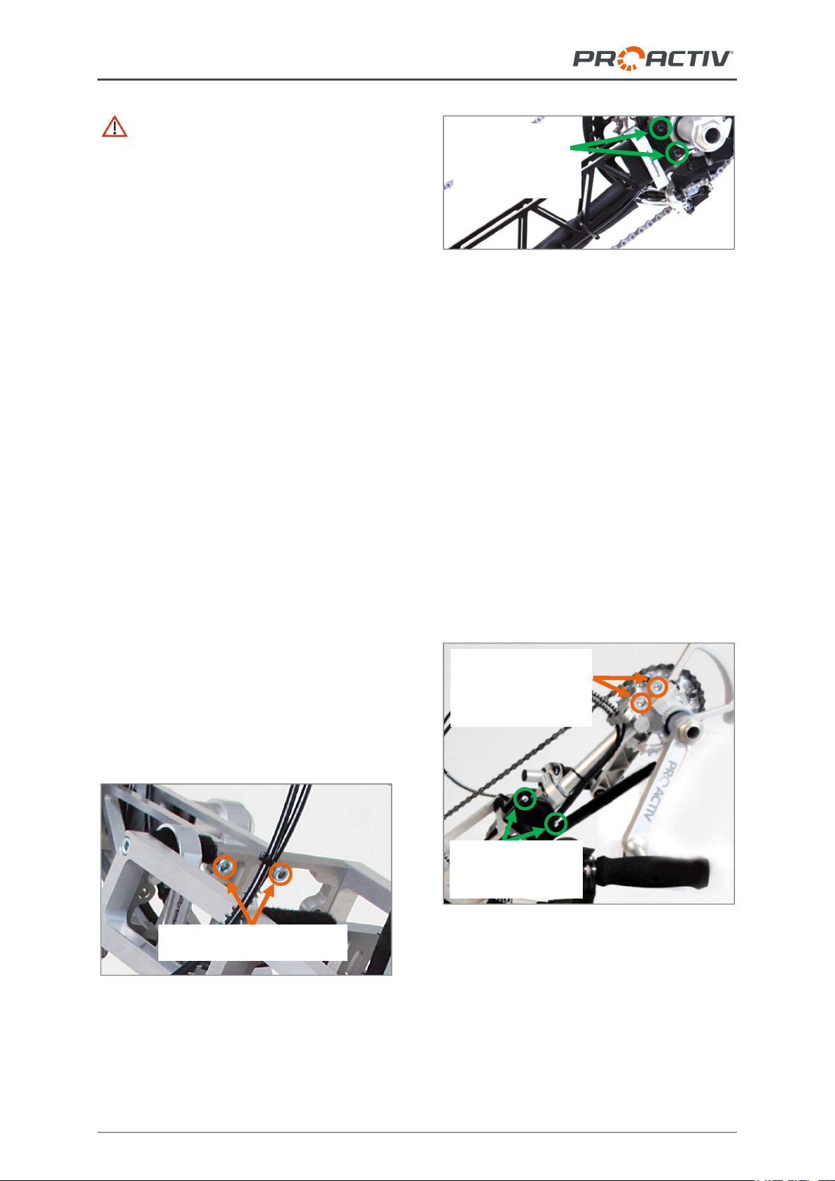
The bottom bracket support can be exchanged
by loosening the four M6 fixing screws (AF
5 mm) on the tip fork bridge and the four M6
fixing screws (AF 4 mm) on the bottom bracket
housing. Then the new bottom bracket support
with another length can be inserted and the 8
fixing screws tightened up to 7 Nm and se-
cured with thread lock fluid. Finally, check the
chain length and the cable lengths and adjust
them if necessary.
Figure 5: M6 fixing screws on the top fork bridge
Figure 6: M6 fixing screws on the bottom bracket
housing
If your product is fitted with an adjustable
bottom bracket support (optional), the bot-
tom bracket position can be adjusted in angle
and height:
The angle is adjusted at the top fork
bridge. To do this, loosen the four M6
clamp screws (AF 5 mm), on the clamp
slightly so that the bottom bracket sup-
port's angle can be adjusted using minimal
force. The angle adjustment is continuous
(as a guide, there is a 12° scale fitted).
When you have finished adjusting the an-
gle, tighten up the four M6 clamp screws
(AF 5 mm) to 7 Nm torque and secure
them with thread lock fluid.
Figure 7: M6 clamp screws for angle and height
adjustment of the bottom bracket position
To adjust the height, two M6 clamp
screws (AF 5 mm) must be loosened on
the bottom bracket housing. Then the bot-
tom bracket housing can be moved along
the bottom bracket support to the desired
M6 fixing screws
on the
bottom bracket
housing
M6 fixing screws on the top
fork bridge
Fastening screws
on the clamp
(angle adjustment)
M6 clamp screws on
the bottom bracket
housing (height
adjustment)

NJ1 el. & FREAK el. compact bike usage instructions
15
position. Then tighten up the four M6
clamp screws (AF 5 mm) to 7 Nm torque
and secure them with thread lock fluid.
For smaller adjustments to the height, infi-
nitely variable adjustments of +/- 25 mm
can be made on the bottom bracket sup-
port. To adjust the height, the two M6
clamp screws (AF 5 mm) must be loos-
ened on the bottom bracket support. Then
the bottom bracket support can be moved
in its mount to the desired position. Then
tighten the four M6 clamp screws (AF
5 mm) to 7 Nm torque and secure them
with thread lock fluid.
Figure 8: M6 clamp screws for adjusting the height
of the bottom bracket position
If you want to make a change to the bottom
bracket position, please contact your rehabilita-
tion specialist dealer or PRO ACTIV.
Please note that, after a large adjustment
to the chain bottom bracket position, the lines
and the cable lengths must be adjusted.
17.1.3 Crank length and grip width
The crank length can be chosen from different
lengths individually to suit the length of the
arms and mobility of the user. Different widths
of bottom bracket shafts and spacers between
the pedal cranks and the rotary axles of the
handles are available to adjust the grip width.
If you want to make a change to the crank
length or grip width, please contact your reha-
bilitation specialist dealer or PRO ACTIV.
Figure 9: Crank length and grip width
17.2 Grips
The grips must be held firmly with both hands
whilst driving and always held so that the ca-
bles and lines are oriented upwards.
Figure 10: Correct grip hold
Always hold onto the crank handles with
both hands while driving, braking, and
manoeuvring. If a driving situation requires you
to take one hand off the crank handle, make
sure the speed has been reduced to the mini-
mum possible beforehand.
17.3 Gear shift
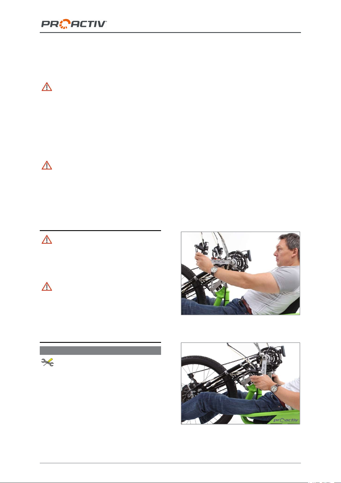
17.3.1 Derailleur
With the derailleur, the gears can only be
changed while the crank is moving. Changing
the gear with the cranks stationary is not pos-
sible. In general, the torque applied to the
cranks should be reduced briefly while chang-
Grip width
Crank
length
Bottom
bracket shaft
Handle rotary
axle
Pedal
crank
M6 clamp screws on the
bottom bracket support
(height adjustment +/-
25 mm)
NJ1 el. & FREAK el. compact bike usage instructions
16
ing the gear so that the gear change can hap-
pen more quickly.
The gearshift control elements are normally
designed so that they can be operated using
thumb / index finger shift control (for mechani-
cal gear systems) or buttons (for electronic Di2
gear systems). With the cassette at the bottom,
switching to the next largest sprocket means a
lower or easier gear and to the next smallest
sprocket a larger or more difficult gear.
Figure 11: Cassette
With the thumb / index finger shift control,
gear changes are achieved by:
"Thumb shifter" – operation by pressing in
the direction of travel with the thumb
“Index finger shifter” – operation by pulling
in the opposite direction of travel with the
index finger or using the thumb to press
against the direction of travel.
The mechanical gearshifts do not provide a
display for the gear selected. There is only an
orientation as to which sprocket is currently
being used via a display above the handle.
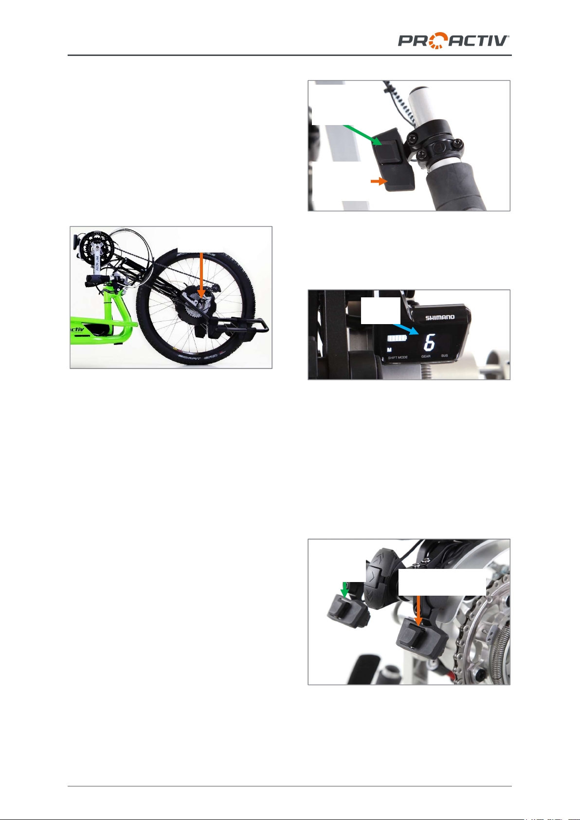
In electronic Di2 gearshift, you can shift up or
down by pressing the button.
On an electronic Di2 gearshift, gear changes
are achieved by:
Pressing the small button with your thumb
to shift up.
Pressing the large button with your thumb
to shift down.
Figure 12: Buttons for shifting up and down
On an electronic gearshift with buttons, the
current gear is shown on the gearshift display.
Figure 13: Displaying the current gear on the display
It is also possible to operate the gearshift by
shifting gears with your chin. One of the two
buttons of the Di2 button on the left in the
direction of travel can be pressed to shift up;
one of the two buttons of the Di2 button on the
right in the direction of travel can be pressed to
shift down. The current gear is always shown
in the gearshift display.
Figure 14: Chin operation via buttons
For shift-
ing up to a
higher gear
For shifting
down to a
lower gear
Cassette
Gear
display
For shift-
ing up to a
higher gear For shifting down
to a lower gear
NJ1 el. & FREAK el. compact bike usage instructions
17
For more information on derailleur gear sys-
tems, please see the instructions provided by
the gear manufacturer.
17.3.2 Charging the battery for Shimano
electronic gearshifts
The rechargeable battery charge level of the
electronic gearshift is also visible on the dis-
play. When the charge state is low (thus when
only one rechargeable battery bar is shown),
the rechargeable battery must be recharged.
Figure 15: Alfine Di2 electronic gearshift battery
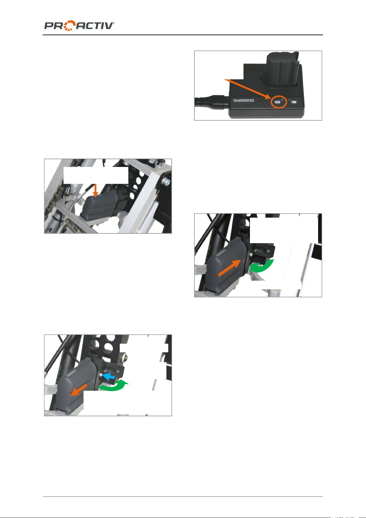
For this purpose, the rechargeable battery is
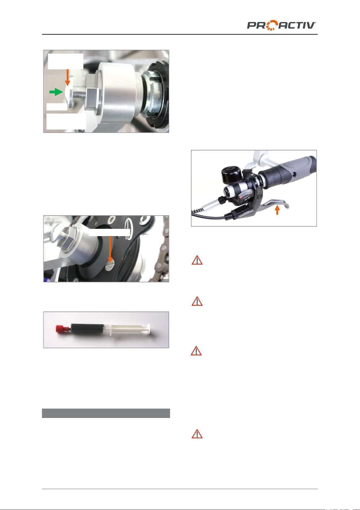
removed as follows: the flap on the side is
opened and the push button is pressed-in (fig-
ure 16). Now the rechargeable battery can be
pulled out along the retaining rail and charged
using the charger included in the scope of
supply. During the charging procedure, an
orange lamp is visible (figure 17).
Figure 16: Remove the rechargeable battery for
charging
Figure 17: Rechargeable battery and charger
The fully charged rechargeable battery (visible
on the charger when the orange lamp goes
out) is pushed back along the retaining rail until
you can feel a slight resistance. When closing
the flap on the side, the rechargeable battery is
completely secured and is connected fixed.
Now the gears are ready for use again.
Figure 18: Reconnect the rechargeable battery after
charging
17.3.3 Bottom bracket gearshift
The bottom bracket gearshift ("Mountaindrive"
gear reduction for hills) is switched on by
pressing the control buttons on the left and
right of the bottom bracket. Here, you can
choose between a 1:1 gear ratio (the left con-
trol button in the direction of travel) or a 2.5:1
gear ratio (the right control button in the direc-
tion of travel).
1. Push the recharge-
able battery in along
the retaining rail
2. Close the flap
3. Pull out the rechargeable
battery along the retaining
rail
1. Open the flap
2. Press the
push button
Display state
charge level
(orange lamp)
Rechargeable battery
switching
NJ1 el. & FREAK el. compact bike usage instructions
18
Figure 19: Left control button of the bottom bracket
gearshift
The bottom bracket gearshift should be lubri-
cated once or twice a year with the supplied
original semi-fluid grease using the syringe.
The semi-fluid grease is filled through the slot-
ted screw.
Figure 20: Slotted screw to lubricate
Figure 21: Original semi-fluid grease in the syringe
For more information, please see the instruc-
tions provided by the manufacturer.
17.4 Brakes
Normally there is one disc and one rim brake
fitted to the product.
Please note that the braking effect can be
strongly reduced by one or all of the following
conditions:
Worn tyre profile
Soiled and wet tyres
Wet, soiled, loose and uneven ground
Dirt and wetness on the brakes and brake
surfaces
Changed weight load
17.4.1 Rim and disc brakes
The brakes are operated manually using the
brake lever.
Figure 22: Brake lever
In the event of abrupt hard braking, there
is a risk that you might fall forward with your
upper body and thereby cause injuries to your-
self.
With rim brakes: Please make sure that
the braking surfaces on the rim and the brake
pads on the rim breaks do not come into con-
tact with oils or greases which could otherwise
impair the braking effect.
With disc brakes: At regular intervals,
check that the brake pads and discs are free
from grease, oil or other contamination. In
addition, check the thickness of the brake disc.
The minimum thickness is printed on the brake
disc. In addition, the brake pad thickness must
be checked with a measuring calliper. The
minimum pad thickness plus support material
is 2.5 mm.
If equipped with V-brake rim brake as
service brake: The setting screw on the brake
lever of the V-brake rim brake must be well
locked. In addition, this setting screw on the
Brake lever
Left control
button
Slotted screw
Press
Left-hand:
1:1 gear ratio

NJ1 el. & FREAK el. compact bike usage instructions
19
brake lever must always be checked for tight-
ness.
Figure 23: Setting screw on the brake lever
You can find further information in the brake
manufacturer's instructions.
17.4.2 Parking brake
An aluminium bracket is attached to the bot-
tom bracket support as a parking brake. With
it, one of the two brakes can be used as a
parking brake. For this purpose, the aluminium
bracket is clamped over the grip and the brake
lever while the brake lever is depressed.
Figure 24: Aluminium bracket as a parking brake
17.4.3 PRO ACTIV back-pedalling brake &
crank release function
The PRO ACTIV back-pedalling brake is a
closed hydraulic system consisting of a gener-
ator unit and a disc brake calliper. The system
has automatic wear compensation for the
brake pads.
The back-pedalling brake is delivered with a
crank release function that allows reverse driv-
ing and manoeuvring via the hand rims. As:
For functional reasons, the back-pedalling
brake always acts as soon as the product
moves backwards. Therefore, the user must
“unlock” the reverse movement first by operat-
ing the crank release function.
The braking function via the backward move-
ment (crank movement against the direction of
acceleration) is always guaranteed – with the
crank release function activated or deactivated.
The braking force applied is adjusted by the
strength of rotating the cranks backwards. The
braking force applied is adjusted by the
strength of rotating backwards.
The crank release function is operated by
pressing the side pressure plate. To activate
the crank release function, the left-hand pres-
sure plate must be operated (seen from the
direction of travel). To return to normal driving
operation with the back-pedalling brake, the
right-hand pressure plate must be operated.
Figure 25: Left- and right-hand pressure plates
Before every trip, test the brakes by mov-
ing the cranks with the normal operating force
in the direction opposite to acceleration. The
drive wheel must not be able to move when the
system is operated.
At regular intervals, check that all of the
connections, lines, bleed screws and the sur-
face of the transmitter unit do not leak and that
all the screw connections on the brake system
are tightened securely.
At regular intervals, check that the brake
pads and discs are free from grease, oil or
other contamination. In addition, check the
thickness of the brake disc. The minimum
thickness is printed on the brake disc. In addi-
Aluminium bracket as a parking brake
Setting screw
on the brake
lever
Deactivating the
crank
release function
Activating the
crank
release function
Other manuals for NJ1 el.
1
This manual suits for next models
1
Table of contents
Other ProActiv Bicycle manuals

ProActiv
ProActiv SPIKE Adaptive bike Troubleshooting guide

ProActiv
ProActiv RAPTOR 4all Troubleshooting guide

ProActiv
ProActiv NJ1 User manual

ProActiv
ProActiv NJ1 el. Troubleshooting guide

ProActiv
ProActiv FREEWAY Troubleshooting guide

ProActiv
ProActiv NJ1 Parts list manual

ProActiv
ProActiv FREAK User manual


