Prochem EVEREST EFI LP User manual

AE
980197
04/26/06
Operating Instructions (ENG)
MODELS: EVEREST EFI LP
EVEREST EFI HP
Read instructions before operating the machine.

EVEREST EFI 980197 06/30/04 1
Welcome…and congratulations on the purchase of your Mobile Cleaning Unit. This instruction manual is a guide
for operating and servicing your unit. Read this manual completely before installing or operating this unit.
This unit offers you personal convenience. All of your instrumentation and controls have been positioned to give
you easy access for operation and daily maintenance.
Proper operation and service are essential to the efficient functioning of this unit. When maintained correctly, this
unit will have a long, trouble-free life.
The service methods described in this manual are explained in such a manner that servicing may be performed
accurately and safely. Proper service varies with the choice of procedure, the skill of the mechanic, and the tools
or parts available. Before attempting any repair, make certain that you are thoroughly familiar with this equipment
and are equipped with the proper tools. Any questions pertaining to operating or servicing this unit should be
directed to your nearest dealer.
THIS UNIT MUST BE INSTALLED BY THE DEALER FROM WHOM YOU PURCHASED IT IN ACCORDANCE
WITH THE PRESCRIBED INSTALLATION PROCEDURES.
MAKE CERTAIN THAT THE WARRANTY CARD IS FILLED OUT AT THE TIME OF INSTALLATION AND IS
RETURNED TO YOUR DEALER.
PROFESSIONAL CHEMICALS CORPORATION
325 SOUTH PRICE ROAD
CHANDLER, ARIZONA 85224
Information in this document is subject to change without notice and does not represent a commitment on the part
of Professional Chemicals Corporation.
YOUR DEALER
NAME: _________________________________________________________________________________________________
ADDRESS: _______________________________________________________________________________________________
PHONE NUMBER: _________________________________________________________________________________________
MODEL _______________________________________
DATE OF PURCHASE __________________________
SERIAL NUMBER ______________________________
SALES REPRESENTATIVE # _____________________

TABLE OF CONTENTS
EVEREST EFI 980197 06/30/04
2
Machine Data Log/Overview.........................1
Table of Contents .........................................2
Receiving Your Unit......................................4
HOW TO USE THIS MANUAL
How to use this Manual. ...............................1-1
SAFETY
Safety Instructions....................................... 2-1
Hazard Intensity Level..................................2-3
OPERATION & SYSTEMS
Technical Specifications...............................3-1
Installation Requirements.............................3-2
Fuel Requirements .......................................3-2
Engine Oil Requirements..............................3-2
Electronic Fuel Injection System...................3-3
Emission Control Information........................3-3
Date Stamp Location....................................3-4
Fuel Pump and Filter ....................................3-4
Error Codes ..................................................3-5
Zenith Distributor Locations..........................3-6
Chemicals & Water.......................................3-7
Components ............................................... 3-8
Water Pumping and Heat Transfer............. 3-12
Chemical Injection System ......................... 3-15
Vacuum System.......................................... 3-16
Pre-run Inspections..................................... 3-17
Priming the Chemical Pump....................... 3-18
Waste Pump............................................... 3-18
Cleaning...................................................... 3-18
Upholstery Cleaning ................................... 3-19
Shutdown and Daily Maintenance (LP) ...... 3-19
High Pressure System................................ 3-19
High Pressure Shutdown &
Return to Low Pressure.............................. 3-20
De-flooding Operations............................... 3-20
Freezing Protection..................................... 3-20
Winterizing Your Unit.................................. 3-21
Removing Anti-freeze from Unit.................. 3-22
MAINTENANCE & SERVICE
Maintenance
Maintenance Schedule ...........................4-1
Key Maintenance Checkpoints ...............4-3
Engine.....................................................4-4
Vacuum Pump ........................................4-5
Water Pump............................................4-6
Vacuum Inlet Filter..................................4-6
Vacuum Relief Valve...............................4-6
Vacuum Drive Belts, Pulleys And Hubs..4-6
Water Pump Drive Belt ...........................4-7
Float Valve (Water Box)..........................4-7
Waste Tank Strainer Basket ...................4-7
Y-Strainer (Outlet)...................................4-7
Temperature Balance Orifice..................4-7
Check Valve (Outlet)...............................4-7
Chemical Pump.......................................4-7
Nitrogen Accumulator .............................4-8
Pressure Regulator.................................4-8
Vacuum Hoses........................................4-8
Pressure Hoses ......................................4-8
Chemical Simulator Valve.......................4-7
Optional Waste Pump-out.......................4-8
Engine Coolant Replacement.................4-8
General Service Adjustments
Check Valve (Solution Outlet).................4-9
Chemical Pump.......................................4-9
Packing Nut Adjustment
(Chemical Metering & Selector Valves) ..4-10
Pressure Regulator.................................4-10
Troubleshooting......................................4-11

TABLE OF CONTENTS
EVEREST EFI 980197 06/30/04
3
PARTS LIST
Framework..................................................5-1
Side Panel, Right........................................5-5
Side Panel, Left...........................................5-7
Chemical Panel...........................................5-9
Control Panel..............................................5-11
Engine.........................................................5-13
Engine Coolant ...........................................5-19
Vacuum Blower...........................................5-21
Water Pump-PP..........................................5-23
Water Pump-PPHP.....................................5-25
Vacuum/Heat Exchanger And Silencer.......5-29
Solution Temperature Control Valve...........5-31
Heli-Coil Heat Exchanger............................5-33
Solution Outlet ............................................5-35
Water Box-PP ............................................5-37
Water Box-PPHP........................................5-39
Pressure Regulator-PP...............................5-41
Pressure Regulator-PPHP..........................5-43
Waste Tank –80 Gal. & 100 Gal.................5-45
Hose Accessories.......................................5-47
Battery-Floor Mount....................................5-49
Automatic Pumpout (Optional)....................5-51
Wand- Titanium Six Jet (Optional)..............5-55
Wand - Quad-Jet (Optional)........................5-57
Wand – Tri-Jet (Optional)............................5-59
Stair Tool (Optional)....................................5-61
Upholstery Tool (Optional)..........................5-63
Shelf Assembly (Optional) ..........................5-65
Water Tank, Dual With
Demand Pump (Optional)...........................5-67
Water Tank-Demand Pump (Optional) .......5-69
Hose Reel (Optional) ..................................5-71
Wiring Diagram...........................................5-73
Hose Diagram-PP.......................................5-74
Hose Diagram-PPHP..................................5-75
Warranty .....................................................5-76

RECEIVING YOUR UNIT
EVEREST EFI 980197 06/30/04
4
ACCEPTANCE OF SHIPMENT
Every part of your cleaning unit was carefully
checked, tested, and inspected before it left our
manufacturing plant. Upon receiving the unit,
make the following acceptance check:
1. The unit should not show any outward signs of
damage. If damaged, notify the delivering carrier
immediately.
2. Check your equipment and packing list. The
cleaning unit should arrive equipped with the
following items (unless otherwise specified).
NOTE: Your distributor from whom you
purchased this mobile cleaning unit is
responsible for the correct installation of this
machine. The dealer is also responsible for
initial training of your operators and
maintenance personnel in the proper operation
and maintenance of this unit.
EQUIPMENT LIST:
1. Console.
2. Waste tank
3. Hose clamps for vacuum hoses.
4. 150 ft. of 2” vacuum hose.
5. 2 vacuum hose connectors.
6. 150 ft. of 1/4" high pressure hose with quick
connects.
7. 50 ft. water supply hose with quick connect.
8. Installation bolting kit.
9. Installation mounting plates.
10. Operation and service manual for engine, water
pump, and vacuum pump manuals.
11. Fuel Pump Assembly and Power Cord.

HOW TO USE THIS MANUAL
EVEREST EFT 980197 07/22/04 1-1
This manual contains the following sections:
-HOW TO USE THIS MANUAL
-SAFETY
-INSTALLATION REQUIREMENTS
-SYSTEMS
-OPERATIONS
-MAINTENANCE & SERVICE
-PARTS LIST
The HOW TO USE THIS MANUAL section will tell
you how to find important information for ordering
correct repair parts.
Parts may be ordered from authorized dealers.
When placing an order for parts, the machine model
and machine serial number are important. Refer to
the MACHINE DATA box which is filled out during
the installation of your machine. The MACHINE
DATA
box is located on the inside of the front cover of this
manual.
The model and serial number of your machine is on
the side approximately where shown.
The SAFETY section contains important information
regarding hazard or unsafe practices of the
machine. Levels of hazards is identified that could
result in product or personal injury, or severe injury
resulting in death.
The OPERATIONS section is to familiarize the
operator with the operation and function of the
machine.
The MAINTENANCE section contains preventive
maintenance to keep the machine and its
components in good working condition. They are
listed in this general order:
-Engine
-Vacuum Pump
-Water Pump
-Drive Belts, Pulleys & Hubs
-Chemical Pumps
-Hoses
-Vac/Exhaust Heat Exchanger
-General Service Adjustments
-Troubleshooting
The PARTS LIST section contains assembled parts
illustrations and corresponding parts list. The parts
lists include a number of columns of information:
-REF – column refers to the reference
number on the parts illustration.
-PART NO. – column lists the part
number for the part.
-DESCRIPTION – column is a brief
description of the part.
-SERIAL NO. FROM – column indicates
the first machine the part number is
applicable to. When the machine design
has changed, this column will indicate
serial number of applicable machine.
The main illustration shows the most
current design of the machine. The
boxed illustrations show older designs. If
column has an asterisk (*), call
manufacturer for serial number.
-NOTES – column for information not
noted by the other columns.
NOTE: If a service or option kit is installed on
your machine, be sure to keep the KIT
INSTRUCTIONS which came with the kit. It
contains replacement parts numbers needed for
ordering future parts.
NOTE: The 98# on the lower left corner of the
front cover is the part number for this manual.
MODEL _____________________________________
DATE OF PURCHASE ________________________
SERIAL NUMBER ____________________________
SALES REPRESENTATIVE # ___________________

EVEREST EFT 980197 06/30/04
2-1
IMPORTANT SAFETY INSTRUCTIONS
When using this machine, basic precautions
must always be followed, including the following:
READ ALL INSTRUCTIONS BEFORE USING THIS MACHINE.
Read the operator's manual before installing or starting this unit. Failure to adhere to instructions
could result in severe personal injury or could be fatal.
Operate this unit and equipment only in a well-ventilated area. Exhaust fumes contain carbon
monoxide which is an odorless and deadly poison that can cause severe injury or fatality. DO NOT run
this unit in an enclosed area. DO NOT operate this unit where the exhaust may enter any building
doorway, window, vent, or opening of any type.
Gasoline is extremely flammable and its vapors can explode if ignited. Store gasoline only in
approved containers, in well-ventilated, unoccupied buildings away from sparks or flames. Never carry
any gasoline or flammable material in the vehicle. Fumes may accumulate inside the vehicle and ignite,
causing an explosion.
DO NOT store any type of flammable material in the vehicle.
This unit must be operated with the vehicle or trailer doors open in order to ensure adequate
engine ventilation.
DO NOT operate engine if gasoline is spilled. Avoid creating any ignition source until the gasoline has
been cleaned up. Never use gasoline as a cleaning agent.
DO NOT place hands, feet, hair, or clothing near rotating or moving parts. Avoid any contact with
moving parts! Rotating machinery can cause injury or fatality.
Never operate this unit without belt guards or heat guards. The high speed moving parts, such as
belts and pulleys, should be avoided while this unit is running. Severe injury, damage, or fatality may
result.
DO NOT service this unit while it is running. The high-speed mechanical parts as well as high
temperature components may result in severe injury or severed limbs.
Never touch electrical wires or components while the engine is running. They can be sources of
electrical shock.
Engine components can get extremely hot from operation. To prevent severe burns, DO NOT touch
these areas while the engine is running - or immediately after the engine is turned off.
DO NOT touch the exhaust system while this unit is running. Severe burns may result.
Before servicing this unit, allow it to "cool down." This will prevent burns from occurring.
Water under high pressure at high temperature can cause burns, severe personal injury, or
fatality. Shut down machine, allow to cool down, and relieve system of all pressure before
removing valves, caps, plugs, fittings, filters, and bolts.
These symbols mean WARNING or CAUTION. Failure to follow warnings and
cautions could result in fatality, personal injury to yourself and/or others, or
property damage. Follow these instructions carefully!

EVEREST EFI 980197 06/30/04
2-1
IMPORTANT SAFETY INSTRUCTIONS
When using this machine, basic precautions
must always be followed, including the following:
READ ALL INSTRUCTIONS BEFORE USING THIS MACHINE.
Read the operator's manual before installing or starting this unit. Failure to adhere to instructions
could result in severe personal injury or could be fatal.
Operate this unit and equipment only in a well-ventilated area. Exhaust fumes contain carbon
monoxide which is an odorless and deadly poison that can cause severe injury or fatality. DO NOT run
this unit in an enclosed area. DO NOT operate this unit where the exhaust may enter any building
doorway, window, vent, or opening of any type.
Gasoline is extremely flammable and its vapors can explode if ignited. Store gasoline only in
approved containers, in well-ventilated, unoccupied buildings away from sparks or flames. Never carry
any gasoline or flammable material in the vehicle. Fumes may accumulate inside the vehicle and ignite,
causing an explosion.
DO NOT store any type of flammable material in the vehicle.
This unit must be operated with the vehicle or trailer doors open in order to ensure adequate
engine ventilation.
DO NOT operate engine if gasoline is spilled. Avoid creating any ignition source until the gasoline has
been cleaned up. Never use gasoline as a cleaning agent.
DO NOT place hands, feet, hair, or clothing near rotating or moving parts. Avoid any contact with
moving parts! Rotating machinery can cause injury or fatality.
Never operate this unit without belt guards or heat guards. The high speed moving parts, such as
belts and pulleys, should be avoided while this unit is running. Severe injury, damage, or fatality may
result.
DO NOT service this unit while it is running. The high-speed mechanical parts as well as high
temperature components may result in severe injury or severed limbs.
Never touch electrical wires or components while the engine is running. They can be sources of
electrical shock.
Engine components can get extremely hot from operation. To prevent severe burns, DO NOT touch
these areas while the engine is running - or immediately after the engine is turned off.
DO NOT touch the exhaust system while this unit is running. Severe burns may result.
Before servicing this unit, allow it to "cool down." This will prevent burns from occurring.
Water under high pressure at high temperature can cause burns, severe personal injury, or
fatality. Shut down machine, allow to cool down, and relieve system of all pressure before
removing valves, caps, plugs, fittings, filters, and bolts.
These symbols mean WARNING or CAUTION. Failure to follow warnings and
cautions could result in fatality, personal injury to yourself and/or others, or
property damage. Follow these instructions carefully!

EVEREST EFI 980197 06/30/04 2-2
DO NOT leave the vehicle engine running while operating this unit.
Dangerous Acid, Explosive Gases! Batteries contain sulfuric acid. To prevent acid burns, avoid contact with
skin, eyes and clothing. Batteries produce explosive hydrogen gas while being charged. To prevent a fire or
explosion, charge batteries only in well ventilated areas. Keep sparks, open flames, and other sources of ignition
away from the battery at all times. Keep batteries out of the reach of children. Remove all jewelry when servicing
batteries.
Before disconnecting the negative (-) ground cable, make sure all switches are OFF. If ON, a spark will occur at
the ground cable terminal which could cause an explosion if hydrogen gas or gasoline vapors are present. When
disconnecting the battery, ALWAYS disconnect the negative (-) terminal FIRST.
DO NOT smoke around the unit. Gas fumes may accumulate and be ignited. The battery is also extremely
flammable. This will prevent possible explosions.
DO NOT damage the vehicle in any manner during installation. When routing fuel lines DO NOT place the
hose in any location where damage may occur to the hose or vehicle. Avoid any contact with moving parts, areas
of high temperature, brake lines, fuel lines, muffler, catalytic converter, or sharp objects.
DO NOT cut or splice any of the vehicle fuel lines during fuel line installation. This may result in fuel leaks
and potentially dangerous conditions. There is no fuel solenoid shut off on this unit. Use only the provided fuel
hose for fuel lines. When traversing the vehicle floor with fuel lines, always use a bulkhead adapter. This will
prevent leakage and ensure that the hose is not punctured by vehicle vibration abrasion.
DO NOT exceed your vehicle's weight limit. The console with waste tank and accessories weighs
approximately 1840 lbs. Make certain to account for any additional accessories in your weight and balance
calculations. Make certain that the vehicle has the correct axle rating. This will prevent unsafe vehicle driving
conditions.
We require high-back seats on all vehicles in which units are to be installed for head and neck protection.
We recommend using a metal partition between the seats and equipment.
DO NOT operate this unit without the water supply attached and turned on. The water pump and other vital
components may be seriously damaged if this unit is permitted to operate dry without water.
DO NOT operate this unit without the filter installed in the waste tank.
Keep your vehicle work area clean. Wands, stair tools, and other accessories must be securely fastened before
driving the vehicle.
All pressure hoses must be rated for 3000 PSI at 250°F. Thermoplastic hoses do not meet these specifications
and should not be used. Severe burns and injury may result if the hoses do not meet these requirements.
The winterizing loop hose assembly, Part #10-805380, is for winterizing use only. If used improperly, live
steam may escape from this hose, causing it to whip around. Burns or injury may result.
Make certain that you receive complete training by the distributor from whom you purchased this unit.
This unit uses high pressure and temperature. Improper or irresponsible use may result in serious injury.
Do not modify this unit in any manner. Improper modification can cause severe personal injury or fatality.
CALIFORNIA PROPOSITION 65 WARNING: Engine exhaust from this product contains chemicals known to the
State of California to cause cancer, birth defects, or other reproductive harm.
HAZARD INTENSITY LEVEL
EVEREST EFI 980197 06/30/04
2-3
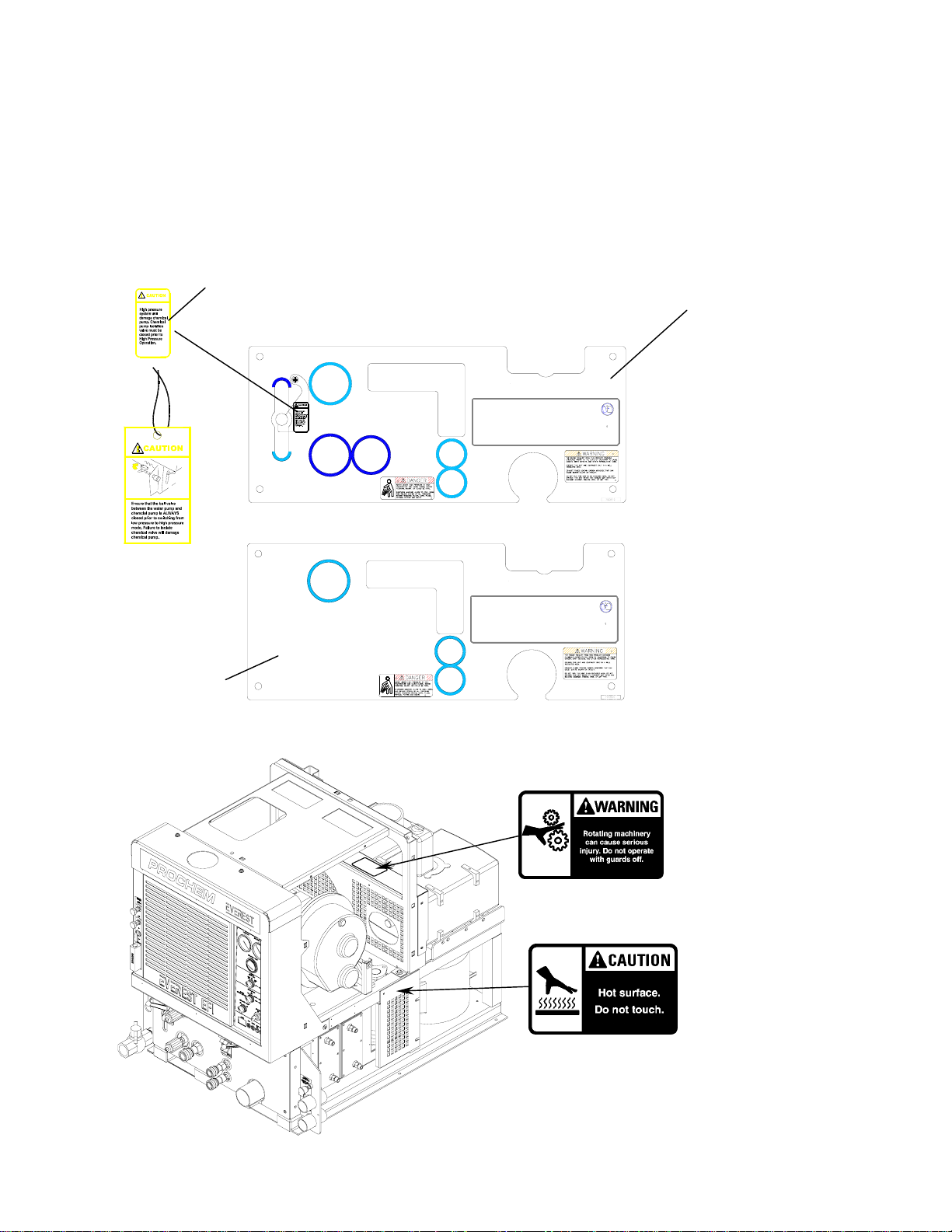
The following WARNING LABELS are found on your cleaning unit . These labels point out
important Warnings and Cautions which should be followed at all times. Failure to follow
warnings and cautions could result in fatality, personal injury to yourself and/or others, or
property damage. Follow these instructions carefully! DO NOT remove these labels.
NOTE: If at any time the labels become illegible, promptly replace them.
HOTWARM SOLUTION TEMPERATURE
CONTROL VALVE
STARTING
HIGH PRESSURE
SOLUTION OUTLET
LOW PRESSURE
SOLUTION SCREEN
CHEMICAL
CHECK VALVE
TEMPERATURE
BALANCE ORIFICE
CONDENSED OPERATING INSTRUCTIONS
1. CONNECTWATER HOSES TO WATER INLET CONNECTIONS AND TURN ON WATER SUPPLY.
2.CONNECT CLEANING AND VACUUM HOSES TO THE DESIREDCLEANING TOOL AND CONSOLE.
3.SET ENGINE SPEED CONTROL SWITCH TO IDLE AND TURN IGNITIONKEY TO START.
4.SET ENGINE SPEED CONTROL SWITCHTO LOW/UPHOLSTERYPOSITION.
5.INSERT CHEMICAL INLETAND PRIME TUBING INTO CHEMICALCONTAINER.
6.TURN CHEMICAL PRIME VALVETO PRIME AND ALLOW CHEMICAL TO CIRCULATE.AFTER ALL AIR BUBBLESHAVE BEEN REMOVED FROM THECHEMICAL
TUBING,TURN THE VALVE TO THE OFF P OSITION,OPEN THE CHEMICAL FLOW AND FLOW SIMULATOR VALVES. SET THE DESIRED CHEMICAL FLOW RATE WHI LE
OBSERVINGTHE FLOWM ETER INDICATOR. FLOW SIMULATOR VALVE MUST BE IN THE OPEN POSITIONTO SET CHEMICAL FLOW. WHEN DESIREDFLOW IS
REACHED,TURN FLOW SIMULATOR VALVE OFF.
7.FOR QUICK HEAT-UP,REFER TO OPERATING INSTRUCTIONS.
1.CLOSE CHEMICAL METERINGVALVE.
2. ALLOW THE UNIT TO RUN FOR 2 MINUTES WITH THE VACUUM HOSE DISCONNECTED TO REMOVEMOISTURE AND SPRAY WD40 (OR EQUIVALENT) INTO
THEVACUUM LUBRICATION CUP. THISW ILL PREVENTCORROSION DUE TO MOISTURE.
3.SET ENGINE SPEED CONTROL SWITCH TO IDLEPO SITIONAND OPEN FLOW SIMULATOR VALVE,A LLOWINGTHE WATER TEMPERATURE TO COOL DOWN.
4.TURN OFF IGNITION SWITCH.
5.DISCONNECT ALL HOSES AND TOOLS.
6.DRAIN WASTE TANK INTO AN APPROVEDSOURCE.
SHUTDOWNAND DAILY MAINTENANCE
SOLUTION
PRESSURE
HIGH PRESSURE
1000-3000PSI
HIGH PRESSURE
SOLUTION REGULATOR
LOW PRESSURE
SOLUTION REGULATOR
LOW PRESSURE
50-1000 PS I
LOW PRESSURE
SOLUTION OUTLETS
CARPET AND
UPHOLSTERY
SOLUTION
Caution Tag
P
a
r
t
#
7
908
1
9
Front panel decal-PP
Part # 790820
Caution label
Part # 500707 Front panel decal-PPHP
Part # 790819
Caution label
Part # 500770
Warning label
Part # 500769
SOLUTION TEMPERATURE
CONTROL VALVE
CONDENSED OPERATING INSTRUCTIONS
1. CONNECT WATERH OSES TO WATER INLET CONNECTIONSA NDTURN ON WATER SUPPLY.
2.CONNECT CLEANING AND VACUUM HOSES TO THE DESIREDCLEANING TOOLAND CONSOLE.
3.SET ENGINE SPEED CONTROL SWITCH TO IDLEAND TURN IGNITIONKEY TO START.
4.SET EN GINESPEED CONTROL SWITCH TO LOW/UPHOLSTERY POSITION.
5.INSERT CHEMICAL INLET AND PRIME TUBINGINTO CHEMICAL CONTAINER.
6. TURNCHEMICAL PRIME VALVE TO PRIME AND ALLOW CHEMICALTO CIRCULATE.AFTERALL AIR BUBBLES HAVEBEEN REMOVED FROMTHE CHEMICAL
TUBING,TURN THE VALVE TO THE OFF POSITION, OPEN THE CHEMICAL FLOW AND FLOW SIMULATORVALVES. SET THE DESIRED CHEMICALFLOW RATE WHILE
OBSERVINGTHE FLOW METER INDICATOR. FLOWSIMULATOR VALVE MUST BE IN THE OPEN POSITIONTO SET CHEMICAL FLOW. WHEN DESIRED FLOW IS
REACHED,TURN FLOW SIMULATORVALVE OFF.
7.FOR QUICK HEAT-UP, REFER TO OPERATINGINSTRUCTIONS.
1.CLOSE CHEMICAL METERINGVALVE.
2.ALLOW THE UNIT TO RUN FOR 2 MINUTES WITH THE VACUUM HOSE DISCONNECTEDTO REMOVEMOISTURE ANDSPRAY WD40 (OR EQUIVALENT)INTO
THE VACUUM LUBRICATION CUP. THIS WILL PREVENT CORROSION DUETO MOI STURE.
3.SET ENGINE SPEED CONTROL SWITCH TO IDLE POSITIONAND OPEN FLOW SIMULATOR VALVE, ALLOWING THEWATER TEMPERATURE TO COOL DOWN.
4. TURN OFF IGNITION SWITCH.
5.DISCONNECT ALL HOSES AND TOOLS.
6. DRAINWASTE TANK INTO AN APPROVED DISCHARGEPOINT.
SOLUTION OUTLETS
CARPET AND
UPHOLSTERY
SOLUTION
SOLUTION SCREEN
SHUTDOWNAND DAILY MAINTENANCE
STARTING
SOLUTION PRESSURE
REGULATOR CHEMICAL
CHECK VALVE
TEMPERATURE
BALANCE ORIFICE
WARM HOT

OPERATIONS
EVEREST EFI 980197 06/30/04 3-1
TECHNICAL SPECIFICATIONS
ITEM DIMENSION/CAPACITY
Engine speed 2200 rpm (medium speed) Water Pump ON
900 rpm (idle speed) Water Pump OFF.
Water pump rpm 1455 rpm
Vacuum pump rpm 3400 rpm
Water flow rate 4.5 GPM (maximum)
Water pump pressure (low pressure) 1000 PSI (maximum)
Water pump pressure (high pressure) 3000 PSI (maximum)
Vacuum relief valve 13” Hg
Waste tank capacity 80 or 100 gallons
Console weight 860 lbs.
Console weight (with waste tank & waste tank
accessories) 1110 lbs (1840 lbs. If waste tank is full)
TORQUE VALUES
Engine hub 480 inch lbs 40 foot/lbs
Vacuum pump hub 192 inch/lbs 16 foot/lbs
Water pump shaft bolt 300 in//lbs 25 foot/lbs
JET SIZING:
Recommended floor tool tip sizing not exceed a total of “.06”. Using larger jet sizes on your cleaning unit may
reduce cleaning temperatures.
Example: Tri-jet wand uses three 9502 jets (95° spray angle w/ 02 orifice).
02 x 3 = 06
When using two floor tools while cleaning with this unit, it is recommended that each tool tip size does not exceed
a total of “.045”.
Example: Tri-jet wand uses three 95015 jets (95° spray angle w/ 015 orifice).
015 x 3 = 045……….06 x 2 tools = 12
Upholstery tool jet size: 80015
Stair tool jet size: 9502

OPERATIONS
EVEREST EFI 980197 06/30/04
3-2
INSTALLATION REQUIREMENTS
DEALER RESPONSIBILITY
NOTE: Your distributor from whom you
purchased this mobile cleaning unit is
responsible for the correct installation of this
machine. The dealer is also responsible for
initial training of your operators and
maintenance personnel in the proper operation
and maintenance of this unit.
1. The unit should NOT be mounted in any motor
vehicle of less than 3/4 ton capacity.
The console with waste tank and accessories
must NOT exceed the vehicle's axle weight limit.
2. If mounting in a trailer, make certain that the
trailer is rated for the total weight of the UNIT
AND TRAILER. Electric or hydraulic brakes
should be provided, and a strict compliance with
any State and Federal vehicle laws must be
maintained. Install unit on tandem axel trailer
only. Single axle trailers are not recommended.
3. The vehicle tires should have a load rating
above the combined vehicle and unit weight.
4. We do not recommend using flooring materials
that absorb water. This could result in rust and
corrosion of the vehicle floor.
5. Padding under rubber floor mats should be
removed before installing this unit.
6. We highly recommend using a drip tray under
the console (Part #790552).
7. If using a trailer, the console should be
positioned so that it balances properly with
respect to the axle. Ten percent (10%) of the
overall unit weight should be on the tongue.
Example: If loaded trailer weight is 2,000 lbs.,
tongue weight needs to be a minimum of
200 lbs. to tow properly.
FUEL REQUIREMENTS2. FUEL
REQUIREMENTS
Use unleaded gasoline ONLY. DO NOT use any
gasoline additives. We recommend the use of clean,
fresh, unleaded gasoline intended for automotive
use. High octane gasoline should NOT be used with
the engine on this unit.
ENGINE OIL REQUIREMENTS3OIL
REQUIREMENTS
Use high quality detergent oil of at least API
(American Petroleum Institute) service class SF or
SG. Select the viscosity based on the air
temperature at the time of operation as shown in the
following table. NOTE: Using less than service
class SF or SG oil or extending oil change intervals
longer than recommended can cause engine
damage.
TEMPERATURE RANGE EXPECTED BEFORE NEXT OIL CHANGE
°F -22 -4 14 32 59 104
°C -30 -20 -10 0 15 40
5W-20
10W
5W-30
10W-30, 10W-40, 10W-50, 15W-40, 15W-50
20W-20, 20W-40, 20W-50

OPERATIONS
EVEREST EFI 980197 06/30/04 3-
3
ELECTRONIC FUEL INJECTION SYSTEM
This unit is equipped with the latest Zenith electronic
fuel injection (EFI) technology. The EFI technology
provides more effective fuel distribution and
improved power management through the use of an
electronic “brain” called the electronic control unit
(ECU). The ECU also provides improved engine
emissions through more effective combustion of the
fuel/air mixture. The fuel system, engine set up, and
exhaust system are systems approved by the
Environmental Protection Agency (EPA). Any
alteration or modification to the system must receive
approval from the EPA.
EMISSION CONTROL INFORMATION
The Zenith Power Products (ZPP) Emission control
label is located on the valve head cover of the
engine near the oil fill cap.
EE
ELE
C

OPERATIONS
EVEREST EFI 980197 06/30/04
3-4
DATE STAMP LOCATION
When referring to an engine for assistance from your
dealer, ProChem, or ZPP please identify your
engine by the serial # and date code stamped on the
machined surface next to the oil dipstick.
FUEL PUMP AND FILTER
Your Everest EFI console was shipped to the dealer
with a specific fuel pump and fuel filter. Ensure that
ONLY these items are used in the installation of your
unit. The EFI system is much more sensitive to
unwanted material in the fuel stream.
Contamination of the fuel stream may clog the
injectors and adversely affect performance. Please
be sure to adhere to the filter maintenance schedule
located in the Operations Section of this manual.
EE
C
FUEL FILTER
# 790858
# 790860
FUEL PUMP

OPERATIONS
EVEREST EFI 980197 06/30/04 3-
5
ERROR CODES
EE
ELE
On rare occasions the engine may experience abnormal operation conditions and shut down. Upon shutdown the
amber light in the upper right corner of the instrument panel will repeatedly flash an error code to help you
determine the root cause of the shutdown. Double-digit numbers are flashed one digit at a time, (i.e. “12” would
be shown as “Flash”, pause, “Flash”, “Flash”). The codes are listed below for your convenience.
CONDITION SEQUENCE RESULT TROUBLE
CODE TROUBLE
FLAG
CODE/FLAG
RETAINED IN
MEMORY WITH
KEY OFF?
1ENGINE OIL PRESSURE SWITCH
INDICATES LOW OIL PRESSURE OIL PRESSURE SWITCH INDICATES OIL PRESSURE
IS LOW FOR 1 COMPLETE SECOND - ENGINE 2NO
1 RPM LIMITED TO 950 MAXIMUM FOR 60 SECONDS 3 NO
2ONCE 60 SECOND TIME LIMIT IS EXCEEDED -
ENGINE SHUTDOWN OCCURS 3NO
1 RPM LIMITED TO 950 MAXIMUM FOR 60 SECONDS 4 NO
2ONCE 60 SECOND TIME LIMIT IS EXCEEDED -
ENGINE SHUTDOWN OCCURS 4NO
4BEGINNING OF DIAGNOSTIC
ROUTINE NO FAULT CONDITION EXITS - SIGNIFIES
BEGINNING OF FLASH CODES 12 YES-ALWAYS
PRESENT
1 TROUBLE CODE IS STORED IN MEMORY 14 3 CODE RETAINED
IN MEMORY
2 RPM LIMITED TO 950 MAXIMUM FOR 60 SECONDS 14 3 FLAG CLEARS
WHEN IGNITION
IS OFF
3ONCE 60 SECOND TIME LIMIT IS EXCEEDED -
ENGINE SHUTDOWN OCCURS 14 3 FLAG CLEARS
WHEN IGNITION
IS OFF
6ENGINE COOLANT SENSOR
INDICATES OPEN CIRCUIT TROUBLE CODE IS STORED IN MEMORY 15 CODE RETAINED
IN MEMOR
Y
7PEDAL POSITION SENSOR OVER
VOLTAGE (OVER 4.5 VOLTS) TROUBLE CODE IS STORED IN MEMORY 21 CODE RETAINED
IN MEMORY
8PEDAL POSITION SENSOR
UNDER VOLTAGE (0 VOLTS) TROUBLE CODE IS STORED IN MEMORY 22 CODE RETAINED
IN MEMORY
9AIR TEMPERATURE SENSOR
INDICATES OPEN CIRCUIT TROUBLE CODE IS STORED IN MEMORY 23 CODE RETAINED
IN MEMOR
Y
10 AIR TEMPERATURE SENSOR
INDICATES SHORT CIRCUIT TROUBLE CODE IS STORED IN MEMORY 24 CODE RETAINED
IN MEMOR
Y
11 MAP SENSOR CIRCUIT
INDICATES HIGH VLOTAGE
(
4.98 TROUBLE CODE IS STORED IN MEMORY 33 CODE RETAINED
IN MEMOR
Y
12 MAP SENSOR CIRCUIT
INDICATES SHORT TO GROUND TROUBLE CODE IS STORED IN MEMORY 34 CODE RETAINED
IN MEMOR
Y
13 OXYGEN SENSOR - LEAN
CONDITION DETECTED TROUBLE CODE IS STORED IN MEMORY 44 CODE RETAINED
IN MEMOR
Y
14 OXYGEN SENSOR - RICH
CONDITION DETECTED TROUBLE CODE IS STORED IN MEMORY 45 CODE RETAINED
IN MEMOR
Y
2ENGINE OVERHEATING
DETECTED (COOLANT >= 239 F)
5
ENGINE COOLANT SENSOR
INDICATES SHORT CIRCUIT OR
EXTREME OVERHEATING OF
ENGINE (COOLANT TEMP >= 266
F)
3TRANSMISSION OIL
TEMPERATURE SWITCH
INDICATES OVERTEMP

OPERATIONS
EVEREST EFI 980197 06/30/0404
3-
6
ZENITH DISTRIBUTOR LOCATIONS
EE
ELE
• CAPITAL ENGINE COMPANY (09046) OH, IN.KY,WV
97 CYPRESS ST. SW PA (WESTERN)
REYNOLDSBURG, OHIO 43068 PHONE:740/964-0089
• CULLUM & BROWN, INC. (09045) KS, MO
1607 WABASH PHONE:316/262-5156
WICHITA, KS 67214 800/362-3222
• DIESEL ELECTRIC SERVICE & SUPPLY (09116) UT
652 W. 1700 SOUTH PHONE:801/972-1836
SALT LAKE CITY, UT 84104
• POWER EQUIPMENT COMPANY (09117) NE, IA
15225 INDUSTRIAL RD. PHONE:402/330-5100
OMAHA, NE 68144
• ENGINE WORKS, INC. (09178) IL
1345 PARAMOUNT PKWY. PHONE:630/879-7977
BATAVIA, IL 60510 800-832-7217
• FRONTIER EQUIPMENT, LTD. (09185) BC, AB
8029 RIVER WAY PHONE:604/946-5531
DELTA, BC CANADA V4G IL3
• GULF ENGINE & EQUIPMENT (09229) LA,MS
2306 ENGINEERS RD. PHONE:504/393-1701
BELLE CHASSE, LA 70037
• HAMILTON ENGINE SALES, INC. (09287) WA, OR, AK
5540 N. E. COLUMBIA BLVD. PHONE:503/288-6714
PORTLAND, OR 97218 800/437-3644
• H. G. MAKELIM COMPANY (09480) CA
219 SHAW RD. PHONE:650/873-4757
SOUTH SAN FRANCISCO, CA 94080
• LOFTIN EQUIPMENT COMPANY, INC. (09490) AZ
12TH NORTH 45TH AVE. PHONE:602/272-9466
PHOENIX, AZ 85043
• M.G. BRYAN EQUIPMENT COMPANY (09503) TX,OK
4834 READING ST. PHONE:214/631-9787
DALLAS, TX 75247
• NORPRO ISUZU ENGINES, INC. (09505) CT, MA, VT, NH, ME, RI
385 TOWN ST. PHONE:860/873-0100
HADDAM, CT 06423
• SOUTHEAST SERVICE & SUPPLY (09698) GA
1721-E OAKBROOK DR. PHONE:770/448-4251
NORCROSS, GA 30093 800/241-4595

OPERATIONS
EVEREST EFI 980197 06/30/04 3-
7
CHEMICAL REQUIREMENTS4.
C
This cleaning unit, due to its chemical injection pump
design, can be used with a variety of water-diluted
chemical compounds (either acidic or alkaline),
depending on the job to be done. However, to obtain
optimum results with this unit, we recommend using
the PROCHEM line of chemicals. For information on
using the cleaning compounds, refer to the
PROCHEM chemical manual.
WATER REQUIREMENTS
Hard water deposits will adversely affect the
plumbing and heat exchange systems on this unit.
The map below will give you an idea of where areas
of high water hardness may occur. However, any
water supply obtained from a well is almost always
hard water and a water softener will be needed to
protect your equipment.
NOTE: Equipment malfunction or component
failure caused by hard water scaling is NOT
covered under the warranty.
If you are operating this unit in an area where the
unit will be using water in which the hardness
exceeds
3-1/2 grains, we highly recommend a suitable water
softener be installed. If using a water softener, it
must have a five (5) GPM (or greater) flow capacity
without any hose constrictions.
Using a water softener will reduce maintenance and
decrease down time caused by hard water scaling. It
will also allow cleaning chemicals to be more
effective in lower concentrations.
If you require a water softener, PROCHEM has a
model to meet your needs. Please contact your
nearest distributor for information, price, and
availability.
HARD WATER MAP

COMPONENTS
EVEREST EFI 980197 04/17/06
3-8
31
30
15
HOT
SOLUTION TEMPERATURE
CONTROL VALVE
WARM
STARTING
LOW PRESSURE
SOLUTION SCREEN
HIGH PRESSURE
1000-3000PSI
SOLUTION
PRESSURE
LOW PRESSURE
SOLUTION REGULATOR
CONDENSED OPERATING INSTRUCTIONS
HIGH PRESSURE
SOLUTION OUTLET
LOW PRESSURE
SOLUTION OUTLETS
CARPET AND
UPHOLSTERY
SOLUTION
HIGH PRESSURE
SOLUTION REGULATOR
LOW PRESSURE
50-1000 PSI
1. CLOSE CHEMICAL METERING VALVE.
2. ALLOW THEUNIT TO RUN FOR 2 MINUTES WITHTHE VACUUM HOSE DISCONNECTEDTO REMOVE MOISTURE AND SPRAYWD40 (OREQUIVALENT) INTO
THE VACUUM LUBRICATION CUP. THIS WILL PREVENT CORROSION DUE TO MOISTURE.
3. SET ENGINETHROTTLE AT IDLE POSITIONA NDOPEN FLOW SIMULATOR VALVE, ALLOWINGTHE WATERTEMPERATURE TOCOOL DOWN.
4. TURN OFF IGNITION SWITCH.
5. DISCONNECT ALL HOSES AND TOOLS.
6. DRAIN WASTE TANK INTO AN APPROVEDSOURCE.
SHUTDOWN AN D DAILY MAINTENANCE
1. CONNECT WATER HOSES TO WATER INLET CONNECTIONS AND TURN ON WATER SUPPLY.
2. CONNECT CLEANINGAND VACUUM HOSES TO THE D ESIREDCLEANING TOOL AND CONSOLE.
3. PULL OUT ENGINE CHOKE,TURN SOLUTION PUMP TO OV ERRIDE AND TURN IGNITIONKEY TO START.
4. PUSH IN ENGINE CHOKE AFTER ENGINE HAS STARTED.
5. SET THR OTTLE AT LOW PO SITION.
6. INSERT CHEMICAL INLETAND PRIME TUBING INTO CHEMICAL CONTAINER.
7. TURN CHEMICALPRIME VALVE TO PRIME AND ALLOW CHEMICAL TO CIRCULATE.AFTER ALL AIR BUBBLES HAVE BEENRE MOVEDF ROMTHE CHEMICAL
TUBING, TURNTHE VALVE TO THE OFF POSITION, OPEN THE CHEMICALF LOWAND FLOW SIMULATOR VALVES. SET THE DESIREDCHEMICAL FLOWRATE WHILE
OBSERVING THE FLOWMETER INDICATOR. FLOW SIMULATOR VALVEMUST BE IN THE OPEN POSITION TO SETCHEMICAL FLOW. WHEN DESIREDFLOW IS
REACHED, TURN FLOW SIMULATOR VALVEOF F.
8. FOR QUICK HEAT-UP,REFER TO OPERATING INSTRUCTIONS.
18
28
29
27
26
24
25
3
4
9
7
11
10
5
6
8
2
1
12
13
14
23
22
21
20 19 17 16

COMPONENTS
EVEREST EFI 980197 06/30/04 3-9
1. WASTE TANK FULL INDICATOR LIGHT
This indicator light is activated when the waste
tank is full. When lit the unit will shutdown
protecting the equipment from damage. This
also indicates that the waste tank must be
emptied before the unit can be brought back in
service.
NOTE: Never dispose of waste water in
storm drains, water ways or on ground
areas. Always dispose of waste in
accordance with local state and federal laws.
2. SERVICE ENGINE SOON
This light, when flashing, signals a problem with
the unit. When this occurs, troubleshooting is
required.
3. VACUUM GAUGE
This gauge indicates in inches of mercury how
much vacuum the system is producing at any
given time.
4. SOLUTION PRESSURE GAUGE
This gauge registers the amount of pressure in
the system.
5. SOLUTION TEMPERATURE GAUGE
This gauge measures the temperature of the
cleaning solution as it exits the machine.
6. WASTE PUMPOUT AND AUXILIARY WATER
PUMP SWITCH
This four-position switch is for activating the
waste pumpout device. It also serves to activate
the fresh water transfer pump. For turning on
pumps, rotate clockwise. For turning off pumps,
rotate counter clockwise.
7. SOLUTION PUMP SWITCH
This switch serves to energize the magnetic
clutch to turn the water pump on or off. Turn
clockwise for activating the pump and counter
clockwise for deactivating the pump.
8. ENGINE SPEED CONTROL
This serves to set the engine speed and
operating parameters. The ‘Low’, ‘Medium’ and
‘High’ settings are set for upholstery cleaning,
single wand cleaning, and dual wand cleaning
respectively.
9. KEY SWITCH
The key switch controls the power for the
machine. To turn the machine on, rotate the
key clockwise until the starter engages the
engine. When machine is running let off the
switch and engine will continue to run. To turn
power off, rotate key counter clockwise to stop
position, engine will then stop.
10. HOUR METER
The hour meter records the number of hours the
unit has run. This serves as a time recorder for
servicing the machine.
11. CIRCUIT BREAKERS
These serve to protect the circuits from
electrical spike and over loads and protects
wires from damage and fire.
12. SOLUTION TEMPERATURE CONTROL
VALVE
This valve enables additional heat exchangers
to contribute more heat to the system if
necessary. By moving the lever to the right it
adds more heat, by moving to the left it removes
heat.
13. OIL CUP
The oil cup allows lubricant spray to reach the
vacuum blower.

COMPONENTS
EVEREST EFI 980197 06/30/04
3-10
14. VACUUM INLETS
The vacuum inlets serve as connecting point for
vacuum hoses.
15. SOLUTION OUTLETS
The solution outlets are the connecting point for
the high pressure cleaning hoses. These
outlets are quick disconnects that allow hoses to
be plugged into the unit.
16. SOLUTION SCREEN
The solution screen is located on the front of the
machine. The function of this screen is to trap
foreign particles from exiting the machine and
plugging the orifices of the cleaning tools. This
screen is part of the machine maintenance
cleaning.
17. CHEMICAL CHECK VALVE
The chemical check valve allows chemicals to
enter the system and travel in a singular
direction to the wand. The chemical check
valve prevents chemicals from traveling up-
stream into the solution system of the unit.
18. HIGH PRESSURE SOLUTION OUTLET
The high pressure solution outlet is the
connecting point for the high pressure hose.
This outlet is a quick disconnect that allows
pressure washing hoses to be plugged into the
unit. (HP unit only)
19. HIGH PRESSURE REGULATOR
The regulating valve controls the amount of
pressure in the pressure washing circuit.
By turning the handle clockwise, It has the effect
of increasing the pressure. Turning it clockwise
has the effect of lowering the pressure. (HP unit
only)
20. WASTE OUTLET
This valve allows the waste tank to be emptied.
Turning clockwise opens the valve.
NOTE: This valve must be closed during
operation.
21. WASTE PUMPOUT
This auxiliary pump serves to empty the waste
collection tank automatically. A float located
inside the tank automatically turns off and on
when the solution level reaches certain points.
22. WARM WATER OUTLET
The warm water outlet allows the cleaning
technician to drain hot water from the water box
for mixing chemical.
Water from this valve is hot.
23. WATER INLET
This quick connect allows the water supply hose
to be connected to the unit.
24. PRESSURE SELECTOR VALVE
This selector valve allows the technician to
switch from high pressure to low pressure. By
moving the handle to the up position, the high
pressure circuit is activated allowing the unit to
be used as a pressure washer. By positioning
the valve handle to the down position, the low
pressure circuit is activated allowing the unit to
be used for carpet cleaning. (HP unit only)
25. LOW PRESSURE REGULATOR
This pressure regulating valve allows the low
pressure circuit to be adjusted by turning the
handle clockwise the pressure will increase, by
turning counter clockwise the pressure will
decrease.
This manual suits for next models
1
Table of contents
Other Prochem Cleaning Equipment manuals


Popular Cleaning Equipment manuals by other brands


Good Way
Good Way TFC-JR Operating and maintenance manual

Good Way
Good Way BioSpray-5 Operating and maintenance instructions

Good Way
Good Way GDS-C40 Operating and maintenance instructions

Kinder
Kinder Eraser HD Installation operation & maintenance

Streamline
Streamline STREAMLFO SF-TR25L-000 instruction manual

Floorwash
Floorwash FB45 Manual of use and maintenance