HydraMaster CTS 403 Flex User manual

HydraMaster
11015 47th Avenue West
Mukilteo, Washington 98275
MAN-47809 Rev. A, JAN 2020
(P/N 000-182-749)
No part of this manual may be reproduced or used in any form or by any means (i.e. graphic, electronic, photocopying or electronic
retrieval systems) without the express written permission of
Harris Research Inc.
Specications and information in this document
are subject to change without prior notice.
All rights reserved. © 2020 Harris Research Inc.
CTS 403 Flex Owner’s
Manual
Manufactured Exclusively for
LTR
REVISION DESCRIPTION
CODE
DATE
BY
CHKD
APPVD
D
C
B
A
A
B
C
D
1
2
3
4
5
6
7
8
8
7
6
5
4
3
2
1
E
F
E
F
MACHINE
FINISH
125
SCALE: 1:8
SHEET 1 OF 2
PROPRIETARY INFORMATION
11015 47th Avenue West,
Mukilteo, Washington 98275
D
SIZE
BREAK ALL SHARP EDGES 0.005-.015
UNLESS OTHERWISE NOTED
DIMENSIONS ARE IN INCHES
PART NUMBER
WEIGHT:
APPLICATION
NEXT ASSY
USED ON
610-050-749
REV
ASSEMBLY, CONSOLE - CTS 403 FLEX
PRJ000245
CTS 403 FLEX 50
750-010-749-10
750-010-758-10
CTS 403 FLEX 35/15
- - -- - -
- - - - - -
- - - - - -
M.B.B.
M.B.B.
L.O.L.
DRAWN
CHECKED
APPVD
01/15/2020
01/15/2020
01/15/2020
TOLERANCES
.X=
.1
.XX=
.03
.XXX=
.010
ANGULAR =
2°
CODE:
567.10


iii: CTS 403 Flex Owner’s Manual
Table of Contents
GENERAL INFORMATION ........................................................................ SECTION 1
Contact Information .......................................................................................... 1-3
Warnings, Cautions and Notices ...................................................................... 1-4
Responsibilities ................................................................................................ 1-8
Machine Specications - Console................................................................... 1-10
Machine Specications - Flex Assemblies...................................................... 1-12
High Altitude Operation .................................................................................. 1-13
Local Water Precautions................................................................................. 1-13
OPERATING INSTRUCTIONS.................................................................. SECTION 2
Before Operating the CTS 403 Flex ................................................................. 2-1
Startup Procedure - Carpet/Upholstery ............................................................ 2-2
Startup Procedure - Tile.................................................................................... 2-4
Shut-Down Procedure ...................................................................................... 2-6
Flex Tank Operation.......................................................................................... 2-7
FREEZE GUARDING ................................................................................ SECTION 3
Freeze Guarding the Carpet/Upholstery System.............................................. 3-2
Freeze Guarding the Tile System ..................................................................... 3-3
MACHINE MAINTENANCE ....................................................................... SECTION 4
Operational Maintenance.................................................................................. 4-2
High Pressure Pump Maintenance................................................................... 4-4
Vacuum System Maintenance .......................................................................... 4-8
Descaling Procedure - Tile.............................................................................. 4-10
Descaling Procedure- Carpet/Upholstery ....................................................... 4-11
Tensioning the Pump Drive Belt...................................................................... 4-12
Pump Tuning Instructions .............................................................................. 4-13
Clean QC Filter and Orice ............................................................................ 4-16
Service Heat Exchanger Indicator - CTS 403 ................................................ 4-17
Cleaning Out The Heat Exchanger Of The CTS 403 ..................................... 4-18
SOLUTION FLOW PATHS ......................................................................... SECTION 5
ELECTRICAL SYSTEM.............................................................................. SECTION 6
TROUBLESHOOTING ............................................................................... SECTION 7
Heating System ................................................................................................ 7-2
Engine............................................................................................................... 7-3
Tile System ....................................................................................................... 7-7
Vacuum System.............................................................................................. 7-10

CTS 403 Flex Owner’s Manual: iv
ASSEMBLIES AND PARTS LIST .............................................................. SECTION 8
Machine Assembly with 35 Gallon Tank and 15 Gallon Tank Parts List ........... 8-4
Machine Assembly with 50 Gallon Tank Parts List ........................................... 8-6
Console Assembly Parts List .......................................................................... 8-13
Blower Assembly Parts List ............................................................................ 8-15
Dash Assembly Parts List............................................................................... 8-18
Engine Assembly Parts List ............................................................................ 8-21
Exhaust Assembly Parts List .......................................................................... 8-22
Diverter Valve Actuator Assembly Parts List................................................... 8-23
Exhaust Diverted Assembly Parts List............................................................ 8-25
Exhaust Diverter Valve Assembly Parts List ................................................... 8-26
Exhaust Manifold Assembly Parts List............................................................ 8-27
Frame Assembly Parts List............................................................................. 8-30
Idler Pulley Assembly Parts List...................................................................... 8-31
Solenoid Valve Assembly Parts List................................................................ 8-32
Back Pressure Switch Mount - CTS 403 Assembly Parts List........................ 8-33
Heat Exchanger Assembly Parts List.............................................................. 8-35
Orice Assembly Parts List ............................................................................. 8-36
Pump Assembly Parts List.............................................................................. 8-38
By-Pass Valve Assembly Parts List ................................................................ 8-39
Silencer Assembly Parts List .......................................................................... 8-40
Top Cover - CTS 403 Flex Assembly Parts List.............................................. 8-41
Water Box Assembly Parts List....................................................................... 8-43
70 Gallon Universal Recovery Tank (URT) Assembly Parts List .................... 8-46
Cover, 70 Gal URT, Single Vac Assembly Parts List ...................................... 8-47.
Vacuum Relieft Valve, URT Assembly ............................................................ 8-48
Dump Hose Hook Up Kit................................................................................. 8-49
Sacricial Anode Assembly............................................................................. 8-50
35 Gallon and 15 Gallon Tank Flex Kit Assembly Parts List ........................... 8-51
35 Gallon Tank Flex Chemical Caddy Assembly Parts List ............................ 8-52
35 Gallon and 15 Gallon Tank Flex Assembly Parts List ................................ 8-54
50 Gallon Tank Flex Kit Assembly Parts List .................................................. 8-55
50 Gallon Tank Flex Chemical Caddy Assembly Parts List ............................ 8-56
50 Gallon Tank Flex Assembly Parts List........................................................ 8-57
Pump Cover Assemlby ................................................................................... 8-58
Pump - Passenger Flex Kit............................................................................. 8-59
Flex Pump Assembly ...................................................................................... 8-60
Flex Pump Replacement Parts Kits................................................................ 8-61
Console Hose Routings.................................................................................. 8-62
v: CTS 403 Flex Owner’s Manual
HOW TO ORDER PARTS .......................................................................... SECTION 9
Warranty Parts Orders...................................................................................... 9-1
Parts Orders ..................................................................................................... 9-1
Emergencies..................................................................................................... 9-1
WARRANTY INFORMATION..................................................................... SECTION 10
Blower ............................................................................................................ 10-1
High Pressure Water Pump ........................................................................... 10-1
Recovery Tank ............................................................................................... 10-1
Chemical System............................................................................................ 10-1
Control Panel ................................................................................................. 10-1
Vacuum And Solution Hoses ......................................................................... 10-2
Cleaning Wand And Tool................................................................................. 10-2
Water Heating System.................................................................................... 10-2
Hard Water Deposits ...................................................................................... 10-2
Flex System Warranty .................................................................................... 10-4

1-1: General Information
1- General Information
The CTS 403 Flex is manufactured exclusively for ChemDry by HydraMaster. It integrates
HydraMaster’s popular and durable truckmounts with the specially designed Flex System
which dispenses ChemDry’s proprietary solutions for carpet and upholstery cleaning, as
well and tile and stone cleaning.
The CTS 403 Flex is available with a 50 gallon tank assembly or a 35 gallon/15 gallon
tank assembly.
D
C
B
A
B
C
D
1
2
3
4
5
6
7
8
8
7
6
5
4
3
2
1
E
F
E
F
A
PACKAGE, CTS 403 FLEX w/ 35 & 15 HRI TANK
REV
750-010-758-10
01/15/2020
01/15/2020
01/15/2020
USED ON
NEXT ASSY
APPLICATION
WEIGHT:
PART NUMBER
UNLESS OTHERWISE NOTED
DIMENSIONS ARE IN INCHES
BREAK ALL SHARP EDGES 0.005-.015
SIZE
C
11015 47th Avenue West,
Mukilteo, Washington 98275
PROPRIETARY INFORMATION
SHEET 1 OF 1
SCALE: 1:20
APPVD
CHECKED
DRAWN
125
MACHINE
FINISH
L.O.L.
M.B.B.
M.B.B.
PRJ000245
CTS 403 FLEX
- - -- - -
- - -
- - -- - -
- - -- - -
- - - - - -
TOLERANCES
.X=
.1
.XX=
.03
.XXX=
.010
ANGULAR =
2°
CODE:
803.97
D
C
B
A
B
C
D
1
2
3
4
5
6
7
8
8
7
6
5
4
3
2
1
E
F
E
F
A
PACKAGE, CTS 403 FLEX w/ 50 HRI TANK
REV
750-010-749-10
01/15/2020
01/15/2020
01/15/2020
USED ON
NEXT ASSY
APPLICATION
WEIGHT:
PART NUMBER
UNLESS OTHERWISE NOTED
DIMENSIONS ARE IN INCHES
BREAK ALL SHARP EDGES 0.005-.015
SIZE
C
11015 47th Avenue West,
Mukilteo, Washington 98275
PROPRIETARY INFORMATION
SHEET 1 OF 1
SCALE: 1:20
APPVD
CHECKED
DRAWN
125
MACHINE
FINISH
L.O.L.
M.B.B.
M.B.B.
PRJ000245
CTS 403 FLEX
- - -- - -
- - -
- - -- - -
- - -- - -
- - - - - -
TOLERANCES
.X=
.1
.XX=
.03
.XXX=
.010
ANGULAR =
2°
CODE:
810.39

General Information: 1-2
The truckmount portion of the CTS 403 Flex has been purposely modied to control the
Flex System, ensuring that the two systems work seamlessly with each other.
The truckmount system utilizes an internal combustion engine to provide the power
necessary to turn both a blower (also referred to as a vacuum pump) and a high pressure
water pump.
The heat of the engine and blower exhausts is transferred to the cleaning solution in the
heat exchanger of the system.
The solution is recovered by the vacuum generated by the blower and is collected in the
recovery tank for proper disposal.
This Owner’s Manual provides operating instructions as well as information required
for proper maintenance and troubleshooting of the CTS 403 Flex. In addition, assembly
illustrations and parts ordering information are included for your convenience.
It is the purpose of this Manual to help you properly understand and maintain your CTS 403
Flex system. Follow the directions and maintenance recommendations carefully, and you
will be rewarded with years of protable, trouble-free operation.
It is imperative that no section be overlooked when preparing for operation of this
equipment. Please read this Owner’s Manual to familiarize yourself with the operation of
the CTS 403 Flex System, paying special attention to all Warnings and Cautions.
This section of the manual contains the following helpful information:
Contact Information
Warnings, Cautions And Notices
Machine Specications - Truckmount
Machine Specications - Flex Assemblies
Responsibilities
Hard Water Precautions
Waste Water Disposal Advisory

1-3: General Information
CONTACT INFORMATION
If you have any questions regarding the operation, maintenance or repair of this machine,
please contact your local distributor.
When calling your distributor, be sure to reference the serial number and date of purchase.
FOR YOUR REFERENCE:
Serial No.______________________________________________
Date of Purchase:___________________
Purchased From (Distributor):_________________________________________

General Information: 1-4
WARNINGS, CAUTIONS AND NOTICES
The manufacturer uses this WARNING symbol throughout the guide to warn of
possible injury or death.
This CAUTION symbol is used to warn of possible equipment damage.
This NOTICE symbol indicates that federal or state regulatory laws may apply,
and also emphasizes supplemental information.

1-5: General Information
During the operation of the truckmount many components are in motion. Never
touch any part of the truckmount that is in motion. Serious injury may result.
During the operation of the truckmount many surfaces will become extremely hot.
Never touch hot surfaces. Serious injury may result.
The operation of this truckmount can produce noise levels exceeding 85 decibels
to a distance of 10 feet. The Occupational Safety and Health Administration
(OSHA) recommends the use of hearing protective equipment if a person is
exposed to an average of 85 decibels over an eight hour period. Check with local
and state agencies concerning hearing conservation rules.
During the operation of the truckmount carbon monoxide and other toxic fumes
are produced. Position the vehicle so that any fumes produced will be directed
away from inhabited areas and any points of building entry (doors, windows, air
conditioning units, fans, etc.). Do not occupy the vehicle while the truckmount is
in operation. Serious injury may result.
During the operation of the truckmount chemicals known to the State of California
to cause cancer, birth defects and other reproductive harm are produced by the
engine exhaust.
Never operate the truckmount with a portable gas container inside the vehicle.
Doing so will increase the risk of re and explosion. Serious injury or death my
result.
Transporting a vented fuel container that presently contains, or has ever contained
in the past, a ammable liquid is strictly forbidden by HydraMaster and by federal
and state regulations. Doing so will increase the risk of re and explosion. Serious
injury or death may result.

General Information: 1-6
Never smoke in or around the truckmount. Doing so will increase the risk of re
and explosion. Serious injury or death may result.
Be cautious when drilling holes through the van oor. Many vans have critical
components mounted directly below the van oor that could be damaged by a
misplaced drill bit.
During the operation of the truckmount the exhaust system will become extremely
hot. Keep all ammable materials away from the truckmount exhaust system.
Failure to do so will increase the risk of re and explosion. Serious property
damage may result.
Never operate the truckmount when the vehicle is tilted more than 10 degrees
in any direction. Doing so will result in improper lubrication of the internal
components, and will increase the risk serious component or engine damage.
Never perform cleaning operations when the truckmount engine is running at the
IDLE throttle position. Failure to do so will increase the risk of serious component
or engine damage.
Never operate the truckmount with the vehicle doors closed. Doing so results in
extremely high temperatures inside the vehicle and will lead to serious component
or engine damage.
Never use concentrated acids or solvents (including d-limonene) in the truckmount
water system or chemical system. Use of these products will cause serious
component damage.

1-7: General Information
Never operate the truckmount with a water hardness reading measuring 3.0
grains per gallon or higher. Using reading than 3.0 grains per gallon will cause
scale to build up inside the truckmount water system. Scale build up causes
serious component damage. Test all water prior to use and use water softening
equipment if necessary.
Never allow water to freeze inside the truckmount. Serious component damage
will occur. Perform all freeze guarding procedures outlined in the digital Owner’s
Manual.
Many vehicles have critical components mounted directly below the oor that can
easily be damaged. Before drilling holes in the oor of the vehicle, inspect the
underside of the vehicle for critical components. Failure to do so may result in
damage to the vehicle.
During the operation of this equipment, surfaces will become hot. Do not allow
components such as hoses to touch hot surfaces. Failure to heed this warning
can result in equipment damage which is not covered by warranty.

General Information: 1-8
RESPONSIBILITIES
The Purchaser’s Responsibilities
Prior to purchasing a van, ensure that the payload is suitable for all of the equipment
that will be installed and transported. This includes and is not limited to: the truckmount,
recovery tanks, fresh water tanks and on-board water, hose reels, hoses, cleaning tools,
chemicals, drying equipment, etc. Payload capacity information is available through the
auto dealer, the manufacturer’s web site, and is also located on the door pillar of the
driver’s side door.
Purchase a heavy duty Group 24 (550 CCA or better) battery for this truckmount. This is
normally available from the installation dealer.
Prior to dropping your van o at the distributor for the truckmount to be installed, have a
spray-on bed liner applied to the oor such as Rhino Lining® or Line-X®.
Prior to operating the truckmount read this manual in its entirety and familiarize yourself
with the information contained here. Special attention should be paid to all cautions and
warnings.
The distributor is responsible for the correct installation of the truckmount. The distributor
is also responsible to train you in the correct and proper operation and maintenance of
the truckmount.
Any modication of the truckmount may void the warranty.
The Distributor’s Responsibility
Acceptance of Shipment
Before accepting the truckmount, check the following:
• The truckmount should be free from any damage during shipping. Do not sign the
delivery receipt until you have closely inspected the truckmount and noted any damage
on the delivery receipt. Hidden damage may be present even if the box looks okay. It
is recommended that the box be opened before signing for the shipment.
• Check the packing list and verify that all items are accounted for.

1-9: General Information
Installation Responsibilities
• Ensure proper payload capacity. It is the distributor’s responsibility to verify that the
equipment package does not exceed the vehicle capacity.
• Ensure installation of a safe fuel tap system and through-oor ttings as provided by
HydraMaster.
• Proper placement of the truckmount, recovery tank, fresh water tank, and accessories
in the vehicle and securing them with bolts and back up plates. The distributor should
verify that the owner is in agreement with the layout.
• Ensure proper connection of the fuel lines.
• Ensure proper connection and installation of the battery. Verify that the battery is in
accordance with HydraMaster’s recommendation.
• Check the pump, vacuum blower and engine oil levels prior to starting the truckmount.
• Start and run the truckmount and check that all systems function properly.
• Test all hoses, wands, etc. for correct operation.
• Ensure timely return of the document package.
Training
The distributor should provide a thorough review of the operation manual with the
purchaser along with instruction and familiarization in:
• How all the truckmount’s systems function.
• All safety precautions and their importance.
• How to correctly start and shut down the truckmount.
• How to correctly clean with the truckmount.
• Where and how often to check and change component oil levels.
• Freezing damage and how to avoid it. This includes explaining proper freeze guarding
procedures.
• How to do basic troubleshooting of the truckmount.
• Hard water damage and how to avoid it. This includes how to determine if hard water
exists in your area and the installation and use of water softening systems.
• The truckmount’s warranty and warranty procedures.

General Information: 1-10
MACHINE SPECIFICATIONS - CONSOLE
Frame Dimensions 24.0" W x 31” H x 36" D
Weight 568 lbs
Engine- Briggs and
Stratton Vanguard 23HP
Oil Type Synthetic 5W-30
Capacity Approx. 1 1/2 quarts (48 oz.)
when changing oil and lter
Engine rpm 3,150 rpm
Fuel Consumption 1.1 gph
Ignition Electric Key Start
Vacuum Blower- Tuthill
3006 Competitor Plus SL
(Dual Splash Lubrication)
Max. Vac. 12” Hg
Oil Type PneuLube or other ISO 100
rating
Gear End Capacity Approx. 7.0 oz.
Drive End Capacity Approx. 5.0 oz.
Blower rpm 3,150 rpm
Water Pump Oil Type 30W non-detergent
Electric Clutch Capacity - oil Approx. 8.0 oz.
Pump Rate 3.5 gallons per minute
Pump rpm 1,750 rpm
Operating Pressure 0 - 1,000 psi
Heating System Stainless Steel and Copper
Hybrid

1-11: General Information
Standard Equipment High Pressure Hose 1/4" High Temperature Lined/
Vinyl Cover - 100 ft.
Vacuum Hose 2" Vacuum Hose- 100 ft.
1-1/2" Wand Whip Line- 10 ft.
Recovery Tank 70 gallon MaxAir Universal
Tank
Through Floor Exhaust Kit
Battery Box
Van Decal
Van Installation Kit
Owner’s Manual (on CD)
Owner’s Guide (paper copy)
Optional Equipment Flex System Tanks 35 gallon/15 gallon
Flex System Tank 50 gallon
Automatic Pump Out (APO) Comet AWDS

General Information: 1-12
MACHINE SPECIFICATIONS - FLEX ASSEMBLIES
50 Gallon Tank
with Frame
Dimensions 12” W x 33” H x 60” L
Weight 113 lbs
35/15 Gallon
Tanks with
Frame
Dimensions 12” W x 33” H x 53” L
Weight 108 lbs
Construction Frames Steel
Tanks Polyethylene

1-13: General Information
HIGH ALTITUDE OPERATION
Elevation plays a key role in how the truckmount will operate. Operation at high altitude
(above 5,000 ft.) may require a high-altitude carburetor jet. Use of this jet at high altitude
will improve power, reduce fuel consumption and help reduce excessive carbon build-up
in the exhaust and heat exchanger systems.
Contact the local Briggs and Stratton dealer or HydraMaster to obtain the
proper jet size. Your local Briggs and Stratton dealer can be located at
http://www.briggsandstratton.com/us/en/support/dealerlocator .
LOCAL WATER PRECAUTIONS
The quality of water varies greatly. Many areas have an excess of minerals in the water
which results in what is commonly called “hard water.” These minerals tend to adhere to
the insides of heater coils and other parts of the machines causing damage and a loss of
cleaning eectiveness. This inuences the reliability and eciency of equipment in direct
proportion to the level of hardness.
Hard Water Advisory
HydraMaster recognizes that any hard water deposits which might occur within the water
system of our truckmounts is a serious problem. The precision technology of truckmount
heat exchanger systems is intolerant of any foreign material. Hard water deposits will
ultimately decrease the performance of the system and are expected to seriously lower
the reliability of the machine.
To validate a machine’s warranty, HydraMaster requires that all machines operating in
designated “Hard Water Areas” (3.0 grains or more per gallon) be tted with a water
softening system, or a properly installed magnetic-type descaler must be used and
maintained. Periodic descaling or acid-rinsing alone is not adequate in these areas.
HydraMaster does not recommend any particular type or brand; however, the relative
eectiveness of some types of magnetic descalers or softeners may require additional
periodic use of descaling agents.
HydraMaster also recommends, in the strongest possible terms, that machines in all
areas be tted with a water softening system for improved operation and reliability.
Failure to take appropriate measures to prevent scale build up can result in
system failure and loss of warranty on aected parts.

General Information: 1-14
Hard Water Area Map
The hard water map, shown in Figure 1-1, denes hard water areas in the continental
United States which compromise uid related components such as hoses, ttings, heaters,
pumps, valves and water-cooled engines. For other countries, hard water area maps can
be obtained from geological societies.
Figure 1-1. Hard Water Map of Mainland United States
The map shown in Figure 1-1 is provided for general reference only. Water
hardness in your geographical location should be conrmed by testing.

1-15: General Information
Water Softener
Cleaning eciency and equipment life is increased, chemical use decreased, and the
appearance of cleaned carpets enhanced when water softeners are incorporated in hard
water areas. HydraMaster strongly urges the use of water softener units with the CTS 403
Flex in areas exceeding 3.0 grains per gallon.
Failure to use a water softener in these areas will invalidate the machine’s warranty.
Referring to the hard water area map shown Figure 1-1, determine the quality of water in
your area and take immediate action if the water hardness exceeds 3.0 grains per gallon.
The relatively low cost of a water softener service is more than made up for by an increased
life of machine parts, reduced chemical costs and continued cleaning eciency. The
water softener will also increase the eectiveness of the cleaning chemicals, therefore
less chemical will be needed.
Contact a water softener distributor in your area for information on the rental of a simple
water treatment unit to carry in your truck. Be sure to charge the water softener in
accordance with the capability of the softener.
For example: If the softener will treat 900 gallons of water and the machine uses an
average of 30 gallons/hour, for an average of 5 hours a day, this equals 150 gallons per
day). In 6 days the machine would use 900 gallons of water. Therefore, the softener
would need to be charged every 6 working days for maximum softening.
Table of contents
Other HydraMaster Cleaning Equipment manuals

HydraMaster
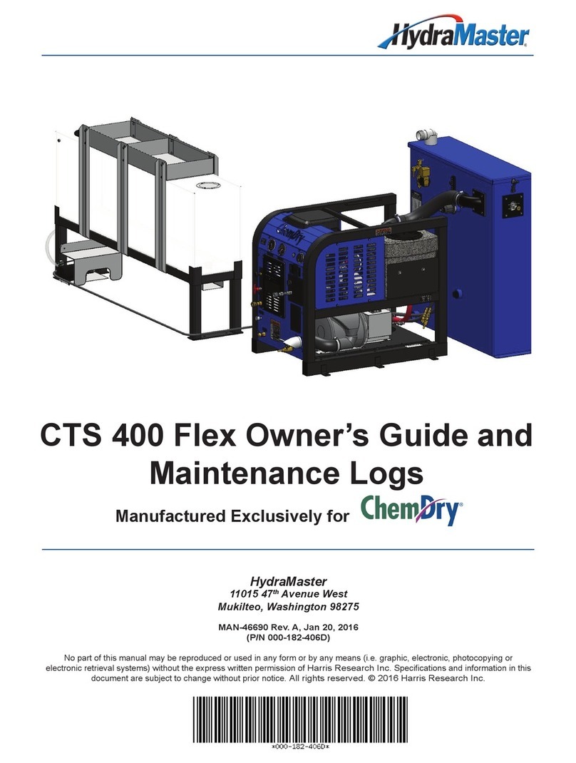
HydraMaster ChemDry CTS 400 Flex User manual

HydraMaster
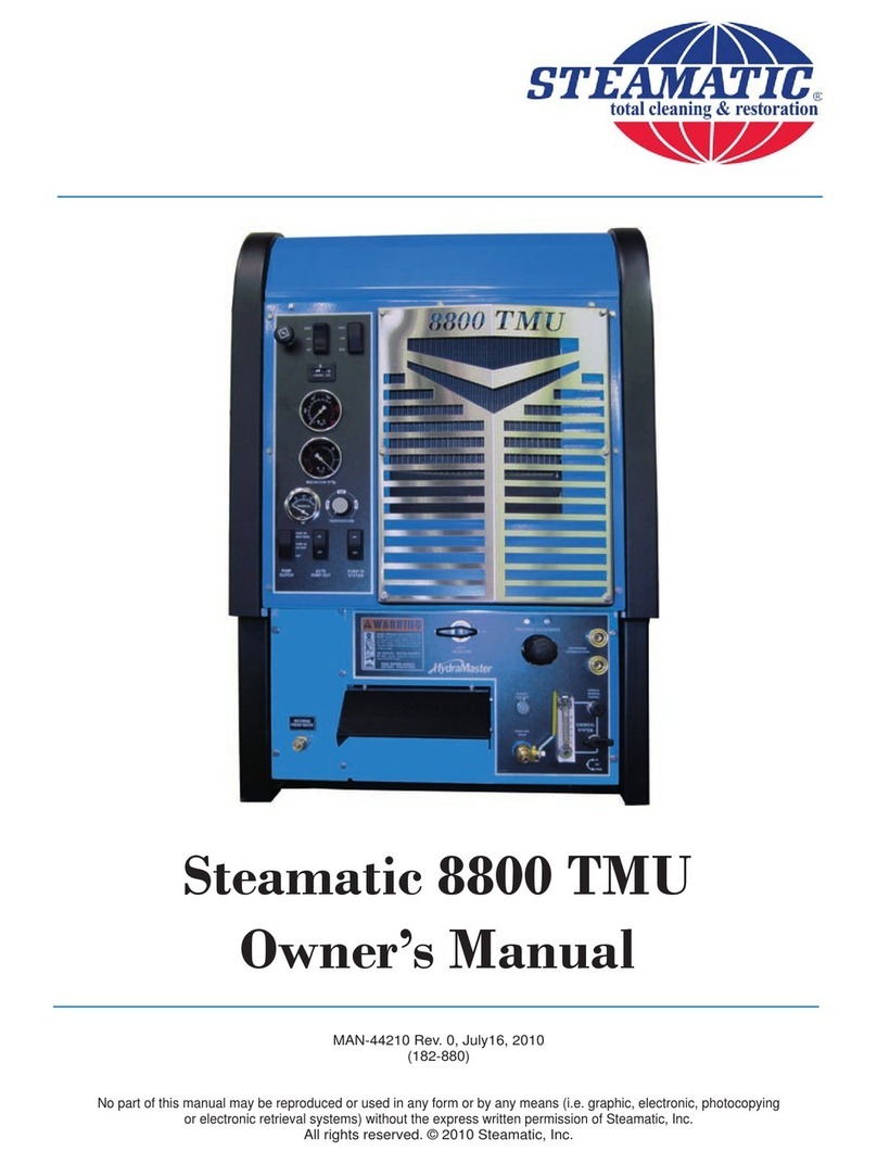
HydraMaster Steamatic 8800 TMU User manual

HydraMaster
HydraMaster CDS 4.8 User manual

HydraMaster
HydraMaster DriMaster HiFlo User manual

HydraMaster
HydraMaster The Master's Touch TMT 3000 User manual

HydraMaster
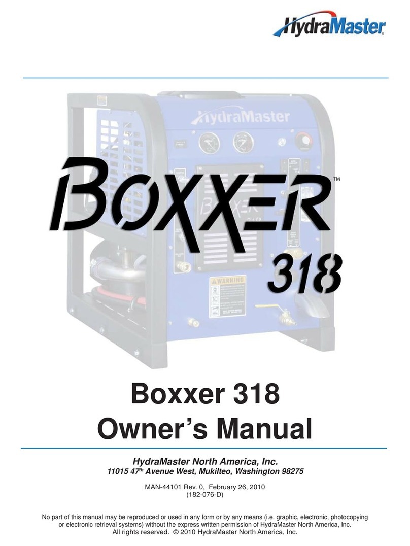
HydraMaster Boxxer 318 User manual

HydraMaster
HydraMaster Titan 625 User manual

HydraMaster
HydraMaster DriMaster II HiFlo User manual

HydraMaster
HydraMaster DriMaster Upholstery Tool User manual