ProCo 240 Instruction manual

Installation, Operation &
Maintenance Manual
Style 240/242
2431 North Wigwam Dr.
Stockton, CA 95205
Phone: 800-344-3246
Fax: 209-943-0242

Proco Products, Inc. Page 1 2013 IOM 240/242
Table of Contents
1.0 Introduction: 2
2.0 Storage and Handling: 2
2.1 Storage: 2
2.2 Large Joint Handling: 3
3.0 Prior to Installation: 3
3.1 Verify System Parameters: 3
3.2 Pipe Anchoring/Supports: 3
3.3 Pipe Alignment: 4
3.4 Concurrent Movement Calculation: 5
3.5 Unpack/Inspect Expansion Joint: 5
4.0 Expansion Joint Installation: 6
4.1 Installation Precautions: 6
4.2 Control Unit Installation Configurations: 7
4.3 Installation Procedures: 9
5.0 System Testing: 14
6.0 Operation and Maintenance Procedures: 14
7.0 Trouble Shooting: 15
Appendix A: Torque Data: 16
Appendix B: Installation Record Sheet: 18

Proco Products, Inc. Page 2 2013 IOM 240/242
1.0 Introduction:
Proco Products, Inc. (Proco) rubber expansion joints are flexible connectors fabricated of natural or synthetic
elastomers and fabrics and if necessary metallic reinforcements, to provide stress relief in piping systems due to
thermal expansion/contraction, mechanical vibration and/or system movements. This installation, operation and
maintenance manual will cover the general practices for the proper installation, operation and maintenance of the
Proco molded spherical type rubber expansion joints. The Proco style of rubber expansion joints covered in this
guide include the style 240 and style 242, molded rubber expansion joints incorporating floating flanges.
Figure 1: Style 240 & 242
Note: The style 242 comes with a reinforcing ring in-between the 2 arches and depending on the size the reinforcing
ring is either embedded in the carcass or exposed.
2.0 Storage and Handling
2.1 Storage
2.1.1Inside:
The ideal storage location for an expansion joint is in a warehouse setting with a relatively dry
and cool location. Store the expansion joint face down on a pallet or wooden platform. Do not
lay other boxes on top of the expansion joint or expansion joint box.
2.1.2 Outside
If the expansion joint is to be stored outside, keep the expansion joint protected in a waterproof
protected crate until ready for installation. Also keep the expansion joint protected from any
external elements such as direct UV exposure and/or animals. Do not lay other boxes on top of
the expansion joint or expansion joint box.

Proco Products, Inc. Page 3 2013 IOM 240/242
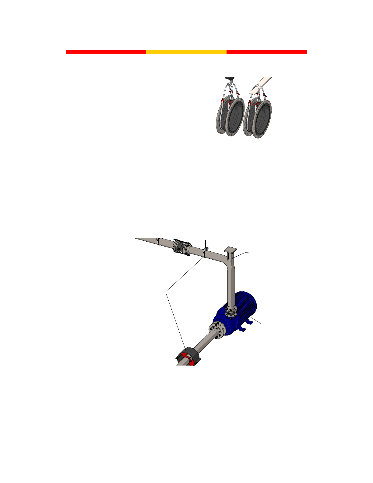
2.2 Large Expansion Joint Handling:
In the case of large size expansion joints,
special care should be taken in loading, hoisting
and lowering, being careful not to hit against
adjacent equipment, forklift tines, crane cables,
etc. Lift utilizing nylon slings around the exterior
of the expansion joint as shown in Figure 2.
Position the slings to each side of the arch; this
will help prevent any damage to the arch as well
as to ensure that the weight is evenly distributed
during installation.
3.0 Prior to Installation:
3.1 Verify System Parameters
Check the system design parameters for the point of installation to ensure that the supplied expansion
joint meets the system requirements and that the system requirements do not exceed the rated
capabilities of the supplied expansion joint. (Pressure, Temperature, Material Compatibility, System
Movements)
3.2 Pipe Anchoring/Supports
Figure 3: Properly Anchored and Supported/Guided System
3.2.1 Anchoring:
Solid anchoring is required wherever the pipeline changes direction and expansion joints should
be located as close as possible to anchor points. If proper anchor points are not used, the
pressure thrust may cause excessive movements in the expansion joint and cause damage.
PROPERLY SUPPORTED
AND GUIDED PIPE SYSTEM
ANCHORED PUMP
PROPERLY ANCHORED
PIPE SYSTEM
PROPERLY SUPPORTED
AND GUIDED PIPE SYSTEM
ANCHORED PUMP
PROPERLY ANCHORED
PIPE SYSTEM
Figure 2: Large Joint Handling

Proco Products, Inc. Page 4 2013 IOM 240/242
3.2.2 Supports:
Check the piping supports where the rubber expansion joint will be installed. Piping to and from
the location of installation for the expansion joint must be properly supported and guided to
ensure that the weight of the piping is not transferred to the expansion joint.
3.3 Pipe Alignment
Inspect the system for proper alignment as stated in the procedures listed below for axial, lateral, angular
and torsional alignment. Piping misalignment in the system should not exceed a maximum of ±1/8” per the
Fluid Sealing Association (FSA). If the maximum allowable misalignment is exceeded, the piping should
be corrected before installation of the expansion joint. The piping must be prepared to receive the rubber
expansion joint, never the contrary, as this would result in compressing, extending, laterally deflecting or
angularly bending the expansion joint until it fits into the available clearance for installation. This will result
in additional movements for the expansion joint, thereby decreasing its movement capabilities during
operation and lead to a possible failure.
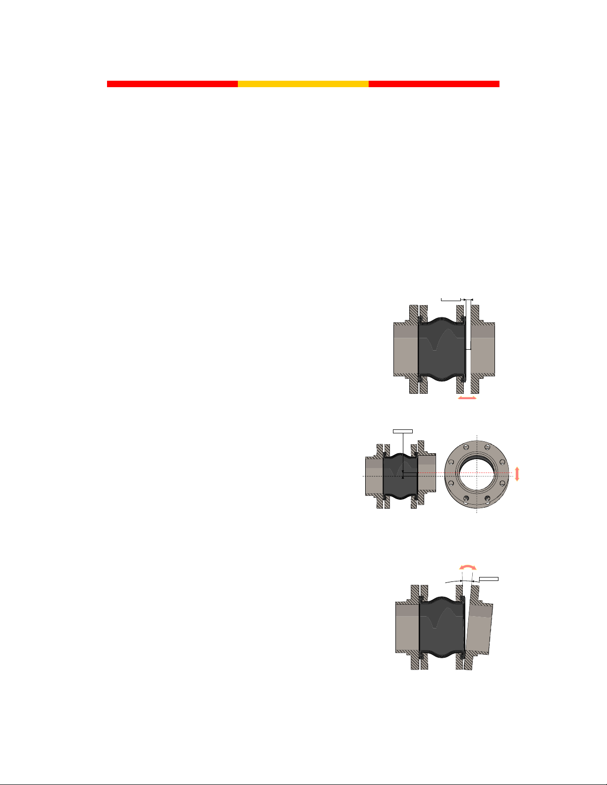
3.3.1Axial Misalignment
To measure for axial misalignment, measure the
perpendicular distance from the inside of one
mating flange to the inside of the other, the area in
which the expansion joint is to be installed. This
measured dimension should correspond to the
ordered expansion joint’s face-to-face or overall
length dimension otherwise an axial misalignment
is indicated.
3.3.2 Lateral Misalignment
To measure for lateral misalignment, place a
level on the outside edge of the mating flanges
and measure the distance across. Repeat the
measurement at least 3 times to obtain a total of
4 measurements evenly distributed around the
circumference of the mating flanges (6-8 total
measurements for large ID expansion joints). Any
variation in the measured dimensions and an
inconsistency in the level, indicates a lateral
misalignment.
3.3.3Angular Misalignment
To measure for angular misalignment between
mating flanges, the distance from one mating flange
to the other will need to me measured. Measure the
perpendicular distance from the inside of one
mating flange to the inside surface of the other
mating flange. Take several of these measurements
in various positions around the mating flanges. Any
variation in the measured dimensions indicates that
the mating flanges are not parallel and are angularly
misaligned.
AXIAL
OFFSETAXIAL
OFFSET
Figure 4: Axial Misalignment
LATERAL OFFSETLATERAL OFFSET
Figure 5: Lateral Misalignment
ANGULAR OFFSET
Figure 6: Angular Misalignment

Proco Products, Inc. Page 5 2013 IOM 240/242
3.3.4Torsional Misalignment
For installations utilizing control units with the Style
240 or 242 molded spherical type expansion joints,
check the flange bolt pattern on each mating flange
and ensure the bolt holes on each flange line up to
each other. Any variation as shown in Figure 7 will
indicate a torsional misalignment and may interfere
with the proper installation of the control units.
3.4 Concurrent Movement Calculation
Concurrent movements are developed when two or more movements in a pipe system occur at the same
time. To perform the calculation for concurrent movements when a pipe system has more than one
movement, use the following equation:
Equation 1: Concurrent Movement Calculation:
The calculation must be <1 for the expansion joint to operation within the concurrent movement
capabilities.
Note: Lateral offsets can be found in two planes.
3.5 Unpack/Inspect Expansion Joint:
Figure 8: Rubber Expansion Joint General Materials of Constructions
Remove the expansion joint from the packaging and if applicable verify that the tag information
corresponds with the point of installation into the system. Check the outer cover and the internal tube or
bonded liner depending on the style of expansion joint ordered for any damage before placing in service.
The cover and tube/liner are designed to keep harmful materials from penetrating the carcass of the joint.
Penetration of the cover or tube/liner by harmful materials can cause premature failure of the expansion
joint. If the outer cover and/or inner tube/liner is damaged during unpacking or installation contact Proco
Products, Inc. by phone: 209-943-6088, by facsimile: 209-943-0242 or by e-mail:
service.
EXPANSION JOINT
TUBE
EXPANSION JOINT
COVER
WIRE SPRING STEEL
SEALING BEAD REINFORCEMENT
SEALING BEAD
INTERMEDIATE RUBBER
LAYER
FABRIC REINFORCEMENT
EXPANSION JOINT
TUBE
EXPANSION JOINT
COVER
WIRE SPRING STEEL
SEALING BEAD REINFORCEMENT
SEALING BEAD
INTERMEDIATE RUBBER
LAYER
FABRIC REINFORCEMENT
TORSIONAL OFFSET
TORSIONAL OFFSET
Figure 7: Torsional
Misalignment
Actual Axial + Actual Lateral + Actual Angular < 1
Rated Axial Rated Lateral Rated Angular

Proco Products, Inc. Page 6 2013 IOM 240/242
4.0 Expansion Joint Installation:
4.1 Installation Precautions:
4.1.1 Adjacent Equipment:
Never install rubber expansion joints next to wafer-type check or butterfly valves. Serious
damage can result to a rubber expansion joint of this type unless installed against full-faced
flanges.
Figure 9: Adjacent Equipment Precaution
4.1.2 Insulating Over Expansion Joint:
It is suggested not to insulate over a non-metallic expansion joint. If insulation is required, it
should be made removable to permit easy access to flanges. Removable insulation will facilitate
periodic inspection of the expansion joint material and allow for tightening of expansion joint
bolts.
Note: Insulation could cause restriction of expansion joint movement and/or excessive heating
of the expansion joint material to exceed the maximum rated capability of the expansion joint.
4.1.3 Heat Tracing Over Expansion Joint:
Do not use heat tracing over expansion joints.
4.1.4 Welding Near Expansion Joints:
Take precautions when welding next to or near a rubber expansion joint. Weld splatted can
damage the rubber material, decreasing overall performance during operation. If welding near a
rubber expansion joint it is suggested to use a welding blanked to protect against any damage.
4.1.5 Painting over Expansion Joints:
Do not paint over the rubber element of the expansion joint.
4.1.6 Multiple expansion joints in line:
Never install more than one standard expansion joint assembly between two main anchors
unless otherwise specified.
NOT A PROPER MATING SURFACE FOR
MOLDED SPHERICAL TYPE EXPANSION JOINTS
VALVE MAY INTERFERE AND DAMAGE
RUBBER EXPANSION JOINT
VALVE MAY INTERFERE WITH PROPER
PLACEMENT OF CONTROL UNIT HARDWARE
NOT A PROPER MATING SURFACE FOR
MOLDED SPHERICAL TYPE EXPANSION JOINTS
VALVE MAY INTERFERE AND DAMAGE
RUBBER EXPANSION JOINT
VALVE MAY INTERFERE WITH PROPER
PLACEMENT OF CONTROL UNIT HARDWARE

Proco Products, Inc. Page 7 2013 IOM 240/242
4.2 Control Unit Installation Configurations:
Figure 10: General Installation Components
Note: Integral Tie Rod designed floating flanges come in multiple styles and the one depicted is of a
general style.
4.2.1 No Control Units Configuration:
The installation configuration shown in Figure 11
does not utilize control units. This configuration
is only applicable for properly anchored and
supported pipe systems.
4.2.2Figure 1: Limit Rod Configuration:
The Figure 1: Limit Rod configuration shown in
Figure 12, otherwise known as Figure 1 is
designed to control only the extension
capabilities of the expansion joint as well as
restrain the pressure thrust loads for non-
properly anchored systems.
MOLDED SPHERE TYPE EXPANSION JOINT
WITH INTEGRAL TIE ROD DESIGNED
FLOATING FLANGES
CONTROL UNIT PLATE
MOLDED SPHERE TYPE EXPANSION JOINT
WITH FLOATING FLANGES
CONTROL ROD WITH
STAKED NUT
WASHER
HEX NUT
CONTROL ROD
COMPRESSION SLEEVE
MOLDED SPHERE TYPE EXPANSION JOINT
WITH INTEGRAL TIE ROD DESIGNED
FLOATING FLANGES
CONTROL UNIT PLATE
MOLDED SPHERE TYPE EXPANSION JOINT
WITH FLOATING FLANGES
CONTROL ROD WITH
STAKED NUT
WASHER
HEX NUT
CONTROL ROD
COMPRESSION SLEEVE
Figure 11: No Control Unit Configuration
Figure 12: Figure 1 Limit Rod Configuration

Proco Products, Inc. Page 8 2013 IOM 240/242
4.2.3 Figure 2: Control Rod Configuration:
The Figure 2: Control Rod configuration
shown in Figure 13, otherwise known as
Figure 2 is designed to control both the
extension and compression capabilities
of the expansion joint as well as restrain
the pressure thrust loads experienced
across the expansion joint.
4.2.4Figure 3: Compression Sleeve Configuration:
The Figure 3: Compression Sleeve
configuration shown in Figure 14,
otherwise known as Figure 3 controls
both the extension and compression
capabilities of the expansion joint as well
as restrain the pressure thrust loads
experienced across the expansion joint.
Instead of utilizing internal hardware to
control the compression capabilities a
compression sleeve is used.
4.2.5 Integral Tie Rod (ITR) Configuration:
The integral Tie Rod (ITR) designed configuration integrates the control unit plates into the
floating flanges when there is a space limitation, flange material conflict or other circumstances
where this design is appropriate for the system. The ITR designed floating flanges come in
multiple configurations/styles depending on number of control rods specified with either internal
hardware or compression sleeves. The ITR design is also designed to restrain the pressure
thrust loads experienced across the expansion joint.
Figure 15: ITR Configuration
Note: Integral Tie Rod designed floating flanges come in multiple styles and the ones shown are
of a general style.
Figure 13: Figure 2 Control Rod Configuration
Figure 14: Figure 3 Compression Sleeve
Configuration

Proco Products, Inc. Page 9 2013 IOM 240/242
4.3 Installation Procedures:
4.3.1 Step 1: Inspect
Inspect the mating flanges to ensure that they are undamaged and clean and free of all foreign
matter before installing the rubber expansion joint. A flat faced mating flange is preferred. If
raised face flanges are used, the use of a ring gasket is required to prevent the metal flange
faces from cutting the rubber bead during installation. If the mating flanges are plastic or FRP
and control units are utilized then it is recommended to use a stiffener ring to reinforce the
mating flange unless otherwise specified.
Figure 16: Flange Preparation
4.3.2 Step 2: Align into System
Place and align the expansion joint into the system. Take care when installing the expansion
joint into the system to prevent and damage to the expansion joint, refer to section 2.2 for large
joint handling if applicable.
Right:
Flanges with correct
I.D. help prevent
damage to rubber.
Wrong::
Insure matting
flanges I.D. is flush
with rubber.
Right:
Weld neck flanges
with correct I.D.
prevent damage to
rubber.
Wrong:
En-even end of pipe
can cause damage
to rubber.
Right:
An Additional Metal
Gasket can be used
to prevent damage to
rubber.
Right:
Well rounded smooth
edge prevents
damage to rubber.
Wrong:
Inner edge of
flanges can damage
rubber..

Proco Products, Inc. Page 10 2013 IOM 240/242
Figure 17: Align into System
Note: It is acceptable, but not necessary to lubricate the expansion joint mating surface with a
thin film of graphite in Glycerin or water to ease disassembly at a later time. (Petroleum
lubricants should not be used on rubber expansion joints.)
4.3.3 Step 3: Add Flange Bolting
Secure the floating flanges in place with the
flange bolting (supplied by other) so that the
bolt head and washer are against the
floating flanges as shown in Figure 18,
leaving the finishing nuts and washers off to
allow for the installation of additional
hardware. The use of stud bolting is
acceptable as long as no more than 2-4
threads extend past the nut facing the
expansion joint. Excessive amounts of
threading extending toward the expansion
joint can cause damage to the expansion
joint as it expands resulting in a reduced
service life and an increased possibility of
failure.
4.3.4 Step 4: Attach Control Unit Plates (If Applicable)
For assemblies utilizing control unit plates,
attach the control unit plates to the outside
edge of the mating flange as shown in
Figure 19 otherwise proceed to step 5. The
control unit plates should be evenly spaced
around the circumference of the mating
flange to help evenly distribute the pressure
thrust loads experienced across the
expansion joint. Note that the number of
control units used is directly correlated with
the operating pressure of the system.
Figure 18: Add Flange Bolting
Figure 19: Add Control Unit Plates

Proco Products, Inc. Page 11 2013 IOM 240/242
4.3.5 Step 5: Tighten Flange Bolting
Once the expansion joint and appropriate hardware are in place complete the installation of the
flange bolting and tighten all bolts and nuts to a “snug” tight fit before torqueing. Torqueing
should then be accomplished in steps gradually and as evenly as possible around the flange.
The bolts should be tightened in an alternating sequence similar to a star pattern shown in
Figure 21 to within the proper torque range specified for the size and style of expansion joint to
be installed. Refer to appendix A for the proper ranges of torque values as well as further
examples of the proper patterns used for torqueing the flange bolting.
Note: Never tighten flange bolting on the rubber expansion joint to the point where there is
metal to metal contact between the mating flange and floating flange. This type of tightening will
crush the rubber sealing bead and cause a premature failure.
Figure 20: Complete Installation of Flange Bolting
Figure 21: Flange Bolting Sample Torque Pattern
46
7
3
2 8
1
5

Proco Products, Inc. Page 12 2013 IOM 240/242
4.3.6 Step 6: Insert Control rod and Appropriate Hardware
Insert the control rod or staked control rod through the control unit plates/ITR Floating flanges
control rod holes while adding the appropriate hardware for the type of control unit configuration
to be installed as shown in Figure 22.
Figure 22: Control Unit Installation; Figure 1 (Top Left), Figure 2 (Top
Right), Figure 3( (Bottom Left), ITR (Bottom Right)
Note: ITR installation hardware shown is of a typical style and may change
depending on application. Consult step 7 to determine the appropriate
compression sleeve length before installation.
4.3.7 Step 7: Setting Control Rod Gap
When setting control rod gaps and/or the compression sleeve length for anchored systems, the
outer nuts are to be positioned to meet maximum extension requirements and the inner nuts or
compression sleeve should be positioned or cut to a minimum length that will allow for the
maximum compression requirements.
Equation 2: Compression Sleeve Length for Figure 3
Compression
Sleeve
Length = Face-To-Face Dimension of
Expansion Joint + Mating Flange
Thicknesses - Total Compression
Required
2 x

Proco Products, Inc. Page 13 2013 IOM 240/242
Equation 3: ITR Compression Sleeve Length
The control rod gaps and/or compression sleeve lengths are to be determined by the project or
site engineer. The combined gaps on the control rods are not to exceed the maximum rated
movement capabilities of the supplied expansion joint. For unanchored systems there should be
no control rod gaps in the control rod hardware, all hardware on the control rods should be snug
to the control unit plates/ITR floating flanges as shown in Figure 24.
Figure 23: Control Rod Gap, Figure 1 (Top Left), Figure 2 (Top Right), Figure 3 (Bottom)
Note: The ITR designs incorporate the same steps in setting the control rod gaps with the
exception that the measurements are taken from the ITR designed floating flanges and not the
control unit plates as depicted in Figure 23.
Figure 24: Control Unit Hardware Locked Down
Note: Lock down all available hardware per type of configuration installed, image depicted is of
a typical lock down configuration for an unanchored system.
HALF OF ALLOWABLE EXTENSIONHALF OF ALLOWABLE EXTENSION
HALF OF ALLOWABLE EXTENSION
HALF OF ALLOWABLE COMPRESSION
HALF OF ALLOWABLE EXTENSION
HALF OF ALLOWABLE COMPRESSION
HALF OF ALLOWABLE EXTENSION
HALF OF ALLOAWBLE COMPRESSION
HALF OF ALLOWABLE EXTENSION
HALF OF ALLOAWBLE COMPRESSION
Compression
Sleeve Length = Face-To-Face
Dimension of
Expansion Joint - Thickness of
Expansion
Joint Flanges - Thickness
of ITR
Plates - Total Compression
Required

Proco Products, Inc. Page 14 2013 IOM 240/242
5.0 System Testing
5.1 System Pressure Test:
Follow pressure test instructions set by site engineer. Lock down all control unit hardware before
beginning any pressure testing of the rubber expansion joints as shown in Figure 24. Pressure test should
not exceed 1.5 times the operating pressure for 10 minutes. Refer to part specific drawing for pressure
rating and details.
5.2 After Pressure Test:
After conducting the pressure test, de-pressurize the system and check the flange bolting. Tighten as
necessary as bolts may loosen as rubber sealing bead takes a set. Follow proper torqueing instructions as
stated in Section 4 Step 5 of the installation procedures.
6.0 Operation and Maintenance Procedures:
6.1 Inspection of Rubber Expansion Joint at Shut-Down:
6.1.1 Cover Inspection:
Rubber expansion joints should be visually inspected at shutdowns. Look for any signs of
cracks in the outer cover that shows exposed fabric reinforcement. If fabric reinforcement is
exposed, the expansion joint must be replaced.
6.1.2 Tube/Liner Inspection:
If inspection of the internal tube or liner of the expansion joint is possible look for signs of
exposed fabric, excessive wear or cracking. If the inner tube or liner shows any of these signs,
the expansion joint must be replaced.
6.2 Expansion Joint Bolt Check:
Check expansion joint at least one week after start-up to ensure that bolts are tight on expansion joint and
the control unit assemblies if applicable. As any rubber-like material takes a “set” after a period of
compression, bolts may loosen; thus resulting in a possible broken seal between the expansion joint and
the mating flange. Periodically check bolts to ensure bolts are tight and tighten as necessary.
Note: Ensure system is de-pressurized before tightening flange bolting.
6.3 Service Conditions:
Make sure the expansion joint operates within the temperature, pressure, vacuum and movement ratings
matching the original requirements. Contact Proco’s Customer Service Department by phone: 800-344-
those specified.
6.4 Expansion Joint Removal:
When removing/replacing the expansion joint from the system the removed expansion joint must not be
reinstalled into the system. This type of expansion joint utilizes a sealing bead for system sealing and is
designed for a one time use. A new expansion joint is required to replace the removed expansion joint.

Proco Products, Inc. Page 15 2013 IOM 240/242
6.5 Spares:
A rubber expansion joint spare should be put in stock in the event a mechanical failure occurs. Stock one
(1) spare for each size purchased. Although these expansion joints are engineered to give long
dependable service, the cost of equipment downtime, in the event of a mechanical failure, can far
outweigh the cost of a spare. Spares will be packaged in waterproof crates and prepared for storage.
7.0 Trouble Shooting:
7.1 Leaking at the Sealing Bead:
Flange bolts may need to be double-checked and retightened to the specified torque settings.
Note: Ensure the system is depressurized before tightening the flange bolting.
7.2 Cracking at the Base of Arch or Flange
Make sure the installed face-to-face dimension is correct so that the joint is not over-extended or over-
compressed. Check to see if the pipes are properly aligned to ensure that there is no excessive
misalignment. Pipes should not be more than 1/8” out of alignment. Check to see if system is properly
anchored or if control units are used. External cracking of cover does not mean failure. This is often
caused by exposure to strong sunlight in an extended condition. If cracking extends to the fabric
reinforcing member, the expansion joint must be replaced.
7.3 Excessive Ballooning of Arch:
Ballooning is usually an indication of deterioration of the joint’s strengthening members or excessive
pressure in the system. Service conditions should be double-checked and a new joint must be installed.

Proco Products, Inc. Page 16 2013 IOM 240/242
Appendix A: Torque Data Table
Table 1: Style 240/242 Torque Data
Nominal
Pipe Size Bolt Torque
Step 1 Rest Step 2 Rest Step 3
in. mm ft·lbs N·m Minutes ft·lbs N·m Minutes ft·lbs N·m
1 25 18 25 30 30 40 60 45-60 60-80
1.25 32 18 25 30 30 40 60 45-60 60-80
1.5 40 18 25 30 30 40 60 45-60 60-80
2 50 18 25 30 30 40 60 45-60 60-80
2.5 65 18 25 30 35 50 60 50-60 70-80
3 80 25 35 30 45 60 60 60-75 80-100
3.5 90 25 35 30 45 60 60 60-75 80-100
4 100 25 35 30 45 60 60 60-75 80-100
5 125 25 35 30 45 60 60 60-75 80-100
6 150 30 40 30 50 70 60 60-75 80-100
8 200 30 40 30 50 70 60 60-75 80-100
10 250 30 40 30 50 70 60 75-85 100-115
12 300 30 40 30 50 70 60 75-85 100-115
14 350 30 40 30 60 80 60 75-95 100-130
16 400 30 40 30 60 80 60 75-95 100-130
18 450 30 40 30 60 80 60 90-95 120-130
20 500 30 40 30 65 90 60 95-185 130-250
24 600 30 40 30 65 90 60 95-185 130-250
30 750 30 40 30 65 90 60 95-220 130-300

Proco Products, Inc. Page 17 2013 IOM 240/242
30"
2
12
6
3
16"
20"
26"
1
7
35
4
8
2
6
11
7
3
10
6
212
8
4
5
9
15 1
5
9
13
4
8
16
2
6
10
14
3
7
11
19 1
5
9
13
17
15
11
7
3
18 4
8
12
16
20
2
14
10
1
5
9
13
24
12
16
20
17
21
4
8
23
19
15
11
7
3
22
18
14
10
6
2
3
4
1
1
24
5
9
13
17
21
25
4
8
1
27
23
14
10
12
16
20
6228
19
15
11
7
26
22
18
4" 8" 12"
Figure 25: Sample Torque Patterns

Proco Products, Inc. Page 18 2013 IOM 240/242
APPENDIX B: Installation Record Sheet
Attached are the Installation record sheets, below is an overview of the details of the attached
installation record sheets.
Expansion Joint Information:
System Installation Information
Installation Date: Date of Installation
1. Medium Gas/Liquid/Steam: Type of Fluid and the State of the Fluid in the System
2. Operating Pressure: Operating Pressure of the System
3. Surge Pressure/Duration: Surge Pressure Experienced in the System and Duration
4. Operating Temperature: Operating Temperature of the System
5. Surge Temperature/Duration: Temperature at Surge Pressure and Duration
6. Confirm Expected Movements in the System:
a. Axial Compression: Expected Axial Compression for Expansion Joint to Compensate
b. Axial Extension: Expected Axial Extension for Expansion Joint to Compensate
c. Lateral Deflection: Expected Lateral Deflection for Expansion Joint to Compensate
d. Angular Deflection: Expected Angular Deflection for Expansion Joint to Compensate
e. Torsional Rotation: Expected Torsional Rotation for Expansion Joint to Compensate
7. Verify System is Properly Anchored/Guided: Verify Anchors and Guides in the System
Notes:
8. Distance to Nearest Anchor Point (each end): Measure the Distance to the Nearest Anchor Points
9. Mating Flange Rating/Type (RF/FF): Rating and Type of Mating Flanges
10. Verify Mating Flanges are Parallel: Verify that the Mating Flanges are Parallel to each other
11. Verify Centerline Alignment: Verify that the Point of Installation is Properly Aligned to the Centerline
12. Verify Axial Alignment: Verify Axial Alignment for the Point of Installation
13. Verify Lateral Alignment: Verify Lateral Alignment for the Point of Installation
14. Verify Angular Alignment: Verify Angular Alignment for the Point of Installation
15. Verify Torsional (Rotational) Alignment: Verify Torsional Alignment for Point of Installation
16. Installation Orientation (Horiz/Vert): Record Installation Orientation of Expansion Joint
17. Installed Face-To-Face Length (measured in 4 positions):
a. 3 O’clock Flange Position: Measure Face-To-Face Dimension at Specified Flange Position
b. 6 O’clock Flange Position: Measure Face-To-Face Dimension at Specified Flange Position
c. 9 O’clock Flange Position: Measure Face-To-Face Dimension at Specified Flange Position
d. 12 O’clock Flange Position: Measure Face-To-Face Dimension at Specified Flange Position
18. Average Bolt Torque: Record Average Bolt Torque to Secure Expansion Joint to Mating Flanges
19. Control Rods:
a. Number of Control Rods: Record Number of Control Rods Used
b. Control Rod Gaps/Compression Sleeve Length: Record Control Rod Gap/Sleeve Length
Notes:
Proco Style: Proco Style of Expansion Joint Supplied
Size (Nom. I.D. x F/F Length): Nominal I.D. x Face-To-Face Length
Purchase Order No.:
Date of Order/Shipment:
Drawing Number:
Tag No.:

Proco Products, Inc. Page 19 2013 IOM 240/242
Document Title
Notes:
This manual suits for next models
1
Table of contents
Popular Industrial Equipment manuals by other brands

APE
APE 475 Operation and maintenance manual

Pneumax
Pneumax CAFS DS Series installation guide

TE Connectivity
TE Connectivity AMP-O-LECTRIC G Customer's manual

3M
3M Fibrlok II instructions

ABB
ABB ReliaGear ND Installation, operation and maintenance manual

JUKI
JUKI M92 SUPPLEMENTARY SETUP INSTRUCTIONS/PARTS LIST