Procopi Climexel ET-NU25 User manual
2009/02 - Indice de révision : I - Code : 0033035
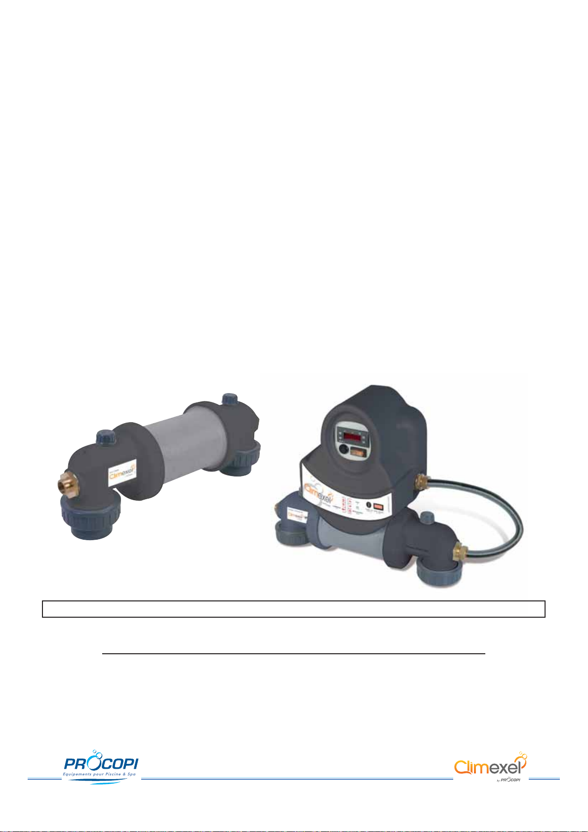
CLIMEXEL
ET-NU25
●
ET-NU40
ET-NU60
●
ET-NU90
ET-CA25
●
ET-CA40
ET-CA60
●
ET-CA90
Echangeur pour le chauffage des piscines
NOTICE D’INSTALLATION ET CONSEILS D’UTILISATION
A lire attentivement et à conserver pour consultation ultérieure.
Français: page 1 - English: page 13 - Deutsch: Seite 25 - Español : página 37
2/48
2009/02 - Indice de révision : I - Code : 0033035
INSTALLATION DE L’ÉCHANGEUR
- L’installation d’un échangeur doit être réalisée dans les règles de l’art, suivant les normes en vigueur.
- Afin de réduire au maximum les déperditions calorifiques, l’échangeur doit être installé le plus près possible de la
chaudière. Si cela est impossible, il faudra calorifuger efficacement les tuyauteries du circuit primaire.
- Les flux des circuits primaire et secondaire devront se croiser dans l’échangeur pour obtenir un échange optimum
des calories.
- L’échangeur devra être raccordé directement au système de production d’eau chaude de la chaudière. Il ne
faudra en aucun cas raccorder l’échangeur à partir d’un réseau existant (circuits radiateurs, réseau de
production d’eau chaude sanitaire).
- Pour la fixation, utiliser le fond de la platine de l’échangeur comme gabarit pour marquer les 4 perçages à effectuer
dans le mur .
By-pass
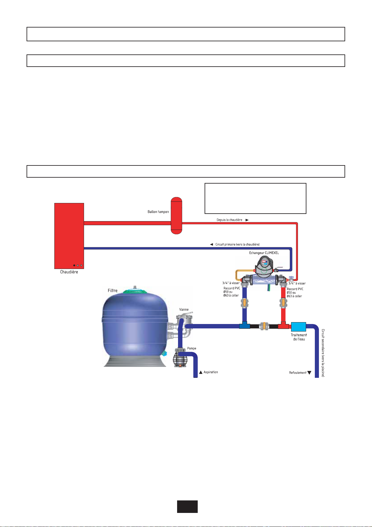
RACCORDEMENTS HYDRAULIQUES
SCHÉMA DE PRINCIPE D’UNE
INSTALLATION
IMPLANTATION
L’échangeur est conçu à l’origine pour un sens de circulation de l’eau de piscine de la gauche vers la droite.
De son côté, l’eau de la chaudière doit entrer à gauche par le circulateur et ressortir du même côté en dessous
par l’échangeur.
La sonde de température est placée dans la cavité côté gauche de l’échangeur (entrée d’eau circuit piscine).
Pour inverser les sens de circulation, procéder comme suit :
- Dévisser les 2 raccords 3 pièces du circulateur et inverser celui-ci. Revisser les raccords 3 pièces.
- Retirer la sonde de température de la cavité sur le côté gauche de l’échangeur et la placer dans la même
cavité sur le côté droit.
3/48
2009/02 - Indice de révision : I - Code : 0033035
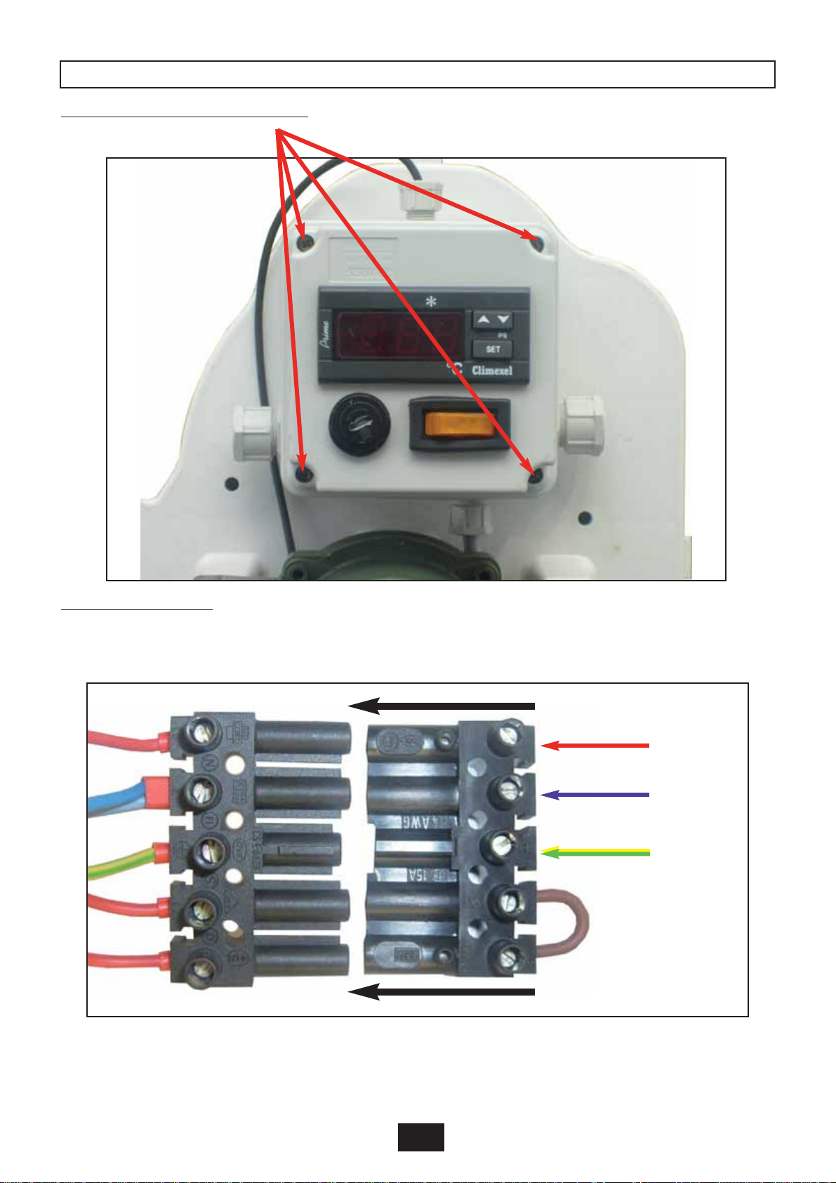
RACCORDEMENTS ÉLECTRIQUES
Desserrer les 4 vis pour ouvrir le capot.
Raccorder sur le bornier
o Le fil rouge sur la phase
o Le fil bleu sur le neutre
o Le fil jaune/vert sur la terre
ATTENTION : afin d'éviter les échauffements, il convient de serrer fermement les vis du bornier.
Raccorder le connecteur mâle sur le connecteur femelle.
Phase
Neutre
Terre

4/48
2009/02 - Indice de révision : I - Code : 0033035
MISE EN SERVICE DE L’ÉCHANGEUR
CIRCUIT PRIMAIRE
- La section d’alimentation du circuit primaire sera déterminée en fonction du débit d’alimentation (voir
caractéristiques des différents modèles).
CIRCUIT SECONDAIRE
- Le circuit secondaire sera raccordé sur le refoulement de la piscine, en by-pass de préférence, après le filtre et
avant toute injection de produit chimique.
- Prévoir les risques de gel durant les périodes de non-utilisation hivernale et en particulier la possibilité de vidanger
la totalité du circuit secondaire (par robinet de purge sur l’installation ou desserrage de l’un des raccords union
de l’échangeur).
LE SCELLEMENT DE L'ÉCHANGEUR EST LA GARANTIE DE L'ÉTANCHÉITÉ DU CHAUFFAGE. LES DEUX ÉCROUS DU CORPS DE
CHAUFFE NE DOIVENT EN AUCUN CAS ÊTRE DÉVISSÉS DE CELUI-CI SOUS PEINE DE ROMPRE LES CONDITIONS DE GARANTIES.
ATTENTION !
LORS DU SERRAGE (OU DU DÉSSERRAGE) DU CIRCUIT PRIMAIRE SUR LES RACCORDS LAITON DE L'ÉCHANGEUR, BIEN MAINTENIR
CES RACCORDS AVEC UNE CLEF DE MANIÈRE QU'ILS RESTENT FIXES. LEUR ROTATION POURRAIT ENDOMMAGER LE CORPS
PLASTIQUE DE L’ÉCHANGEUR ET ENTRAÎNER UNE FUITE, ANNULANT TOUTE GARANTIE.
IMPORTANT
Une fois les raccordements hydrauliques et électriques terminés, suivre la chronologie suivante :
- Mettre en fonctionnement la pompe de filtration, et s'assurer qu'il n'y a aucune fuite sur le circuit hydraulique.
- Ouvrir les vannes d'isolement du circuit primaire de la chaudière
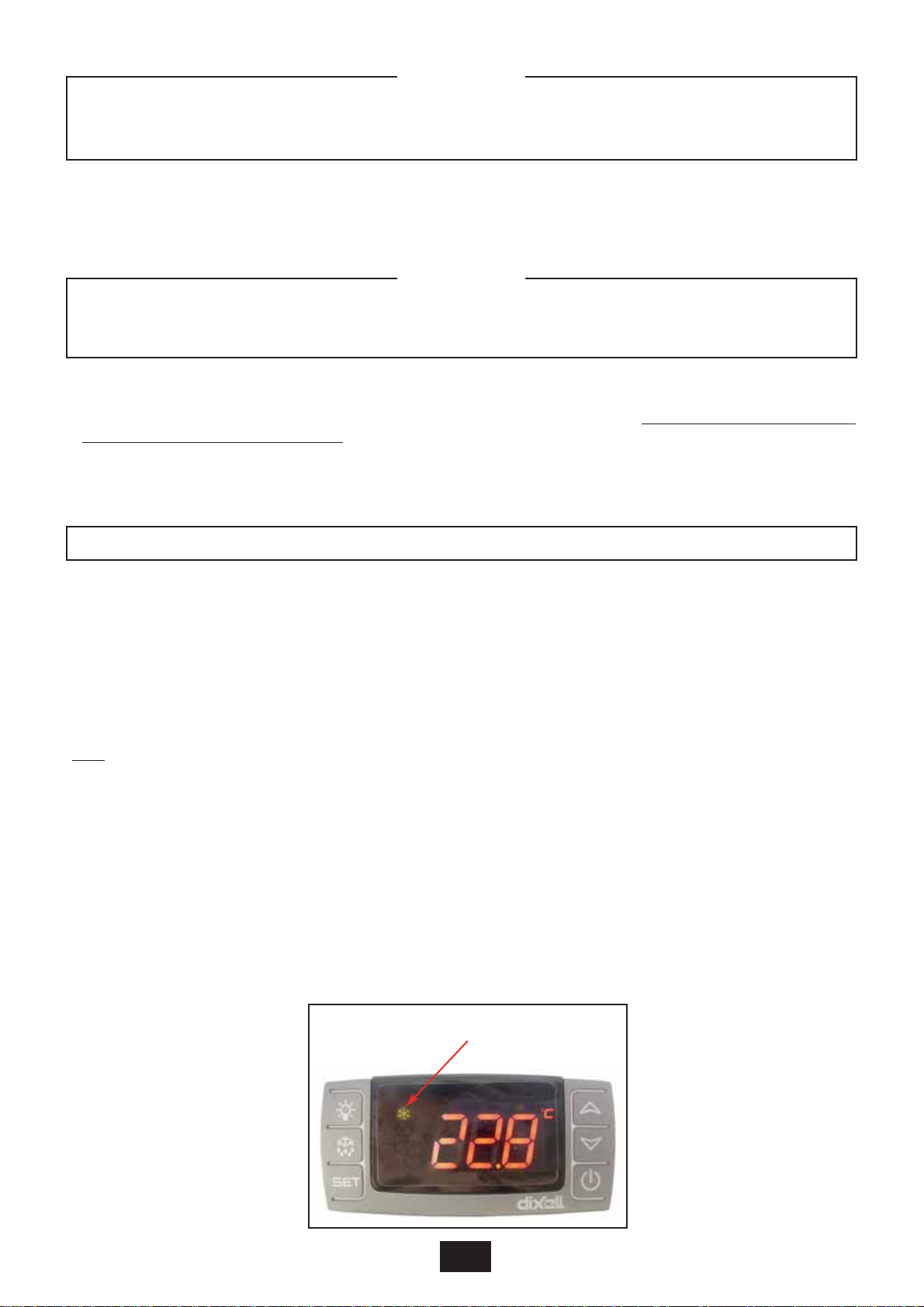
- Alimenter l'échangeur en électricité. Le thermostat à affichage digital s'allume et clignote en affichant “888”
pendant quelques secondes, puis la température de l'eau de la piscine s'affiche.
- Placer l'interrupteur de commande sur "Marche".
- Si la température de la piscine est inférieure à la température de consigne, le voyant de l’interrupteur s’allume,
indiquant que le circulateur est en fonctionnement.
Nota :Le voyant n’est allumé que lorsque le circulateur fonctionne.Il est donc normal que lorsque l’eau de la piscine
est à la température désirée l’interrupteur soit enclenché et le voyant reste éteint.
Modification de la température de consigne :
Presser la touche " SET " (moins de 4 secondes), la valeur du point de consigne va apparaître. Ce point de
consigne ne peut être modifié qu'avec la touche " UP " et " DOWN " en ayant lâché la touche "SET".
Pour augmenter la température désirée, appuyer sur la touche "UP", par impulsions successives jusqu'à la
température souhaitée (maximum 45° C), puis “ SET “ ou attendre 10 secondes.
Pour abaisser la température désirée, appuyer sur la touche "DOWN", par impulsions successives jusqu'à la
température souhaitée (minimum 15° C), puis “ SET “ ou attendre 10 secondes.
Une fois le point de consigne désiré affiché, attendre quelques secondes le retour de l’affichage de la température
de la piscine.
Nota : Par défaut le point de consigne est programmé à 15°C.
Le flocon allumé indique un fonctionnement normal

- Couper l’alimentation électrique en tête de ligne des accessoires de l’échangeur (circulateur, thermostat,..).
- Procéder à l’hivernage du groupe de filtration en vidant toutes les canalisations.
-Vidanger soigneusement les canalisations du circuit secondaire, surtout si celui-ci emprunte un chemin extérieur
entre l’échangeur et le groupe de filtration.
- Procéder à la vidange du corps de l’échangeur (par robinet de purge sur l’installation ou desserrage de l’un des
raccords union de l’échangeur).
CONTRÔLES DE FONCTIONNEMENT
HIVERNAGE
Pour s'assurer que l'échangeur fonctionne normalement :
- Approcher l'oreille du circulateur et en manipulant l'interrupteur " Marche/Arrêt " de l'échangeur, s'assurer, au
léger sifflement émis par le moteur, que le circulateur fonctionne normalement.
- Prendre d'une main la canalisation d'arrivée et de l'autre celle de retour du circuit primaire, une différence
sensible de température doit être ressentie.Si c'est le cas, la preuve est faite d'un bon échange thermique entre
les circuits primaire et secondaire et donc un bon fonctionnement de l'échangeur. Le corps de l’échangeur doit
être froid ou au maximum à la température de la piscine.
- Après un arrêt prolongé de l'installation (hivernage), il est possible que le circulateur ne démarre pas. Pour le
débloquer, il suffit de dévisser la pastille centrale et à l'aide d'un tournevis, tourner l’axe dans un sens ou dans
un autre. Une fois le circulateur démarré, revisser la pastille centrale.
Si malgré les contrôles ci-dessus un mauvais fonctionnement de l'échangeur persistait, celui-ci pourrait avoir pour
cause :
- Un mauvais dimensionnement du circuit primaire (pertes de charge trop importantes).
- Une mauvaise purge d'air du circuit primaire.
- Un mauvais fonctionnement du thermostat principal de la chaudière (eau du primaire pas assez chaude).
- Un sous dimensionnement de la chaudière.
L'afficheur indique "P1" en permanence et l'échangeur ne fonctionne pas :Vérifier le raccordement de la sonde
ou changer cette dernière.
TABLEAU DES CODES
Kw Code Désignation
25 9200200 Echangeur CLIMEXEL ET-NU 25 kW
40 9200400 Echangeur CLIMEXEL ET-NU 40 kW
60 9200600 Echangeur CLIMEXEL ET-NU 60 kW
90 9200900 Echangeur CLIMEXEL ET-NU 90 kW
25 9202200 Echangeur CLIMEXEL ET-CA 25 kW
40 9202400 Echangeur CLIMEXEL ET-CA 40 kW
60 9202600 Echangeur CLIMEXEL ET-CA 60 kW
90 9202900 Echangeur CLIMEXEL ET-CA 90 kW
5/48
2009/02 - Indice de révision : I - Code : 0033035

6/48
2009/02 - Indice de révision : I - Code : 0033035
CARACTERISTIQUES TECHNIQUES

7/48
2009/02 - Indice de révision : I - Code : 0033035
8/48
2009/02 - Indice de révision : I - Code : 0033035
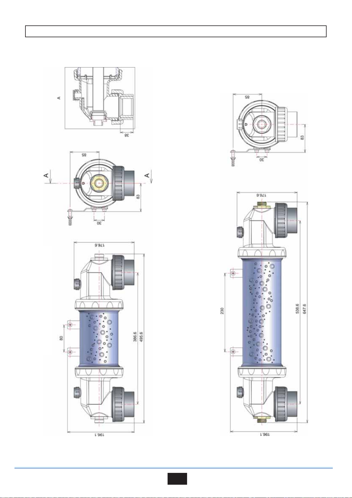
ENCOMBREMENTS MODÈLES NUS
MODÈLES 25 kW et 40 kW
MODÈLES 60 kW et 90 kW
9/48
2009/02 - Indice de révision : I - Code : 0033035

10/48
2009/02 - Indice de révision : I - Code : 0033035
ENCOMBREMENTS MODÈLES PRÉMONTÉS
MODÈLES 25 kW et 40 kW
MODÈLES 60 kW et 90 kW

11/48
2009/02 - Indice de révision : I - Code : 0033035
Notes
. . . . . . . . . . . . . . . . . . . . . . . . . . . . . . . . . . . . . . . . . . . . . . . . . . . . . . . . . . . . . . . . . . . . . . . . . .
. . . . . . . . . . . . . . . . . . . . . . . . . . . . . . . . . . . . . . . . . . . . . . . . . . . . . . . . . . . . . . . . . . . . . . . . . .
. . . . . . . . . . . . . . . . . . . . . . . . . . . . . . . . . . . . . . . . . . . . . . . . . . . . . . . . . . . . . . . . . . . . . . . . . .
. . . . . . . . . . . . . . . . . . . . . . . . . . . . . . . . . . . . . . . . . . . . . . . . . . . . . . . . . . . . . . . . . . . . . . . . . .
. . . . . . . . . . . . . . . . . . . . . . . . . . . . . . . . . . . . . . . . . . . . . . . . . . . . . . . . . . . . . . . . . . . . . . . . . .
. . . . . . . . . . . . . . . . . . . . . . . . . . . . . . . . . . . . . . . . . . . . . . . . . . . . . . . . . . . . . . . . . . . . . . . . . .
. . . . . . . . . . . . . . . . . . . . . . . . . . . . . . . . . . . . . . . . . . . . . . . . . . . . . . . . . . . . . . . . . . . . . . . . . .
. . . . . . . . . . . . . . . . . . . . . . . . . . . . . . . . . . . . . . . . . . . . . . . . . . . . . . . . . . . . . . . . . . . . . . . . . .
. . . . . . . . . . . . . . . . . . . . . . . . . . . . . . . . . . . . . . . . . . . . . . . . . . . . . . . . . . . . . . . . . . . . . . . . . .
. . . . . . . . . . . . . . . . . . . . . . . . . . . . . . . . . . . . . . . . . . . . . . . . . . . . . . . . . . . . . . . . . . . . . . . . . .
. . . . . . . . . . . . . . . . . . . . . . . . . . . . . . . . . . . . . . . . . . . . . . . . . . . . . . . . . . . . . . . . . . . . . . . . . .
. . . . . . . . . . . . . . . . . . . . . . . . . . . . . . . . . . . . . . . . . . . . . . . . . . . . . . . . . . . . . . . . . . . . . . . . . .
. . . . . . . . . . . . . . . . . . . . . . . . . . . . . . . . . . . . . . . . . . . . . . . . . . . . . . . . . . . . . . . . . . . . . . . . . .
. . . . . . . . . . . . . . . . . . . . . . . . . . . . . . . . . . . . . . . . . . . . . . . . . . . . . . . . . . . . . . . . . . . . . . . . . .
. . . . . . . . . . . . . . . . . . . . . . . . . . . . . . . . . . . . . . . . . . . . . . . . . . . . . . . . . . . . . . . . . . . . . . . . . .
. . . . . . . . . . . . . . . . . . . . . . . . . . . . . . . . . . . . . . . . . . . . . . . . . . . . . . . . . . . . . . . . . . . . . . . . . .
. . . . . . . . . . . . . . . . . . . . . . . . . . . . . . . . . . . . . . . . . . . . . . . . . . . . . . . . . . . . . . . . . . . . . . . . . .
. . . . . . . . . . . . . . . . . . . . . . . . . . . . . . . . . . . . . . . . . . . . . . . . . . . . . . . . . . . . . . . . . . . . . . . . . .
. . . . . . . . . . . . . . . . . . . . . . . . . . . . . . . . . . . . . . . . . . . . . . . . . . . . . . . . . . . . . . . . . . . . . . . . . .
. . . . . . . . . . . . . . . . . . . . . . . . . . . . . . . . . . . . . . . . . . . . . . . . . . . . . . . . . . . . . . . . . . . . . . . . . .
. . . . . . . . . . . . . . . . . . . . . . . . . . . . . . . . . . . . . . . . . . . . . . . . . . . . . . . . . . . . . . . . . . . . . . . . . .
. . . . . . . . . . . . . . . . . . . . . . . . . . . . . . . . . . . . . . . . . . . . . . . . . . . . . . . . . . . . . . . . . . . . . . . . . .
. . . . . . . . . . . . . . . . . . . . . . . . . . . . . . . . . . . . . . . . . . . . . . . . . . . . . . . . . . . . . . . . . . . . . . . . . .
. . . . . . . . . . . . . . . . . . . . . . . . . . . . . . . . . . . . . . . . . . . . . . . . . . . . . . . . . . . . . . . . . . . . . . . . . .

12/48
2009/02 - Indice de révision : I - Code : 0033035
S. A au capital de 7 000 000 €- R.C.S/Rennes B 333 263 846 000 37

13/48
2009/02 - Indice de révision : I - Code : 0033035
CLIMEXEL
ET-NU25
●
ET-NU40
ET-NU60
●
ET-NU90
ET-CA25
●
ET-CA40
ET-CA60
●
ET-CA90
Heat exchanger for swimming pools
INSTALLATION AND OPERATING INSTRUCTIONS
To be read carefully and kept for future reference

14/48
2009/02 - Indice de révision : I - Code : 0033035
INSTALLATION OF THE HEAT EXCHANGER
- Heat exchangers must be installed in accordance with the rules of the art and the standards in effect.
- The heat exchanger should be installed as close as possible to the boiler in order to minimise heat loss. If this is
not possible, you will need to lag the primary circuit pipes with thermal insulation.
- For optimum heat exchange, the flows in the primary circuit and secondary circuit must cross within the exchanger.
- The heat exchanger must be connected directly to the boiler’s hot water production system. It should under no
circumstances be plumbed into an existing network (radiator circuit, residential hot water supply circuit, etc.)
- To mount the heat exchanger, use the support plate as a template to mark out the 4 holes that need to be drilled
in the wall.
By-pass
Filter
Boiler
Buffer tank
Fromtheboiler
Primary circuit (to the boiler)
CLIMEXEL heat exchanger
screwed
PVC Union
or
solvent or
solvent
PVCUnion
screwed
Valve
Pump
Suction Retun
Water
treatment
Secondary circuit (to the pool)
HYDRAULIC CONNECTIONS
SCHEMATIC DIAGRAM OF A STANDARD
INSTALLATION
INSTALLATION SITE
The heat exchanger was originally designed for a pool water flow from left to right.
The water from the boiler enters from the left, flows through the heat exchanger in the opposite direction to the
pool water and exits on the same side lower down.
The temperature sensor is inserted into the recess on the left-hand side of the heat exchanger (at the pool water
entry point).
To invert the direction of water flow, do the following :
- Unscrew both of the 3 part unions on the circulator and invert them. Screw the 3 part unions back together.
- Take the temperature sensor out of the housing on the left-hand recess and insert it into the corresponding
recess on the right hand side.

15/48
2009/02 - Indice de révision : I - Code : 0033035
ELECTRICAL WIRING
Loosen the 4 screws to remove the cowling
Connect the terminals
o Red wire to live
o Blue wire to neutral
o Yellow/green wire to earth
CAUTION: to avoid heating of the termninals, ensure that the terminal screws are well tightened.
Plug the male connecter into the female connector.
Live
Neutral
Earth
16/48
2009/02 - Indice de révision : I - Code : 0033035
STARTING UP THE HEAT EXCHANGER
PRIMARY CIRCUIT
- The cross section of the primary circuit will be determined by the rate of flow into the heat exchanger (refer to the
technical specifications of the various models).
SECONDARY CIRCUIT
- The secondary circuit is plumbed into the pool return line, preferably in by-pass, after the filter and before the
injection of any chemical products.
- Make the necessary provisions to cope with the risk of freezing during winter, notably ensure that it is possible to
drain the secondary circuit completely (by means of a drain valve mounted on the installation or by loosening one
of the unions on the heat exchanger).
THE HEAT EXCHANGER SEAL ENSURES LEAKTIGHTNESS OF THE HEATING CIRCUIT. THE TWO NUTS ON THE BODY OF THE HEAT
EXCHANGER SHOULD UNDER NO CIRCUMSTANCES BE LOOSENED. FAILURE TO COMPLY WITH THIS INSTRUCTION COULD LEAD TO
CANCELLATION OF GUARANTEES.
ATTENTION !
WHEN TIGHTENING (OR LOOSENING) THE PRIMARY CIRCUIT CONNECTIONS ON THE EXCHANGER’S BRASS UNIONS, HOLD THE
UNIONS STEADY USING A WRENCH TO PREVENT ANY MOVEMENT. ANY ROTATION OF THE BRASS UNIONS COULD DAMAGE THE
PLASTIC BODY OF THE HEAT EXCHANGER AND GIVE RISE TO A LEAK, CANCELLING ANY GUARANTEES.
IMPORTANT
Once the exchanger is plumbed in and wired, do the following:
- Start up the filtration pump and make sure that there are no leaks on the hydraulic circuit.
- Open the isolating valves on the boiler’s primary circuit.
- Power up the heat exchanger. The digital display on the thermostat lights up, 888 blinks for a few seconds, then
the pool temperature is displayed.
- Move the control switch to "On".
- If the pool temperature is lower than the set point temperature, the indicator light on the switch is illuminated
indicating that the circulating pump is running.
Note:The indicator light is only illuminated while the circulating pump is running.Therefore, while the pool water is
at the desired temperature, it is normal for the indicator light to be out although the switch is set to
"On"
.
Changing the temperature set point:
Press the " SET " key and hold it down (less than 4 seconds), the value of the set point is displayed.The set point
can be modified using the " UP " and " DOWN " keys once the "SET" key is released.
To increase the desired temperature, press the "UP" key, press the key repeatedly until the desired temperature
is displayed (maximum 45° C), then press " SET " or wait 10 seconds.
To decrease the desired temperature, press the "DOWN" key, press the key repeatedly until the desired
temperature is displayed (minimum 15° C), then press " SET " or wait 10 seconds.
Once the desired set point is displayed, wait for a few seconds, the pool temperature will be displayed again.
Note: the default temperature setting is 15°C.
While the snowflake is lit up, the device is running
normally
17/48
2009/02 - Indice de révision : I - Code : 0033035
- Cut the power supply to the heat exchanger accessories (circulating pump, thermostat, etc.)
- Prepare the filtration group for winterizing by draining the various lines.
- Carefully drain the secondary circuit lines, especially if the secondary circuit runs outside between the heat
exchanger and the filter.
- Drain the heat exchanger body (using the drain valve on the installation or by loosening one of the unions.
OPERATING CONTROLS
WINTERIZING
To ensure that the heat exchanger is running correctly:
- Bring your ear close to the circulating pump, toggle the heat exchangers On/Off switch, if the circulating pump is
running correctly you should hear a low whistling coming from the pump motor.
- Place one hand on the inlet pipe of the primary circuit and the other on the outlet pipe of the primary circuit, you
should feel a noticeable temperature difference. A noticeable temperature difference indicates that there is an
efficient heat exchange between the primary and secondary circuits and, therefore, that the heat exchanger is
running correctly. The body of the heat exchanger should be cold or at most at the same temperature as the
pool.
- After a prolonged shut-down (winterizing), the circulating pump may fail to start up. To release it, unscrew the
central unscrew the central stud using a screw driver, rotate the shaft one way and then the other. Once the
circulating pump starts up, replace the central stud.
If, after carry out the above, the heat exchanger continues to malfunction this could be due to:
- Incorrect sizing of the primary circuit (pressure drop too high).
- Insufficient air purge of the primary circuit.
- Malfunction of the boiler’s main thermostat (the water in the primary circuit is not hot enough).
- Under sizing of the boiler.
The display shows "PIl" and the heat exchanger is not running. Check the sensor connections or replace the
sensor.
TABLE OF CODES
Kw Code Designation
25 9200200 Heat exchanger CLIMEXEL ET-NU 25 kW
40 9200400 Heat exchanger CLIMEXEL ET-NU 40 kW
60 9200600 Heat exchanger CLIMEXEL ET-NU 60 kW
90 9200900 Heat exchanger CLIMEXEL ET-NU 90 kW
25 9202200 Heat exchanger CLIMEXEL ET-CA 25 kW
40 9202400 Heat exchanger CLIMEXEL ET-CA 40 kW
60 9202600 Heat exchanger CLIMEXEL ET-CA 60 kW
90 9202900 Heat exchanger CLIMEXEL ET-CA 90 kW
18/48
2009/02 - Indice de révision : I - Code : 0033035
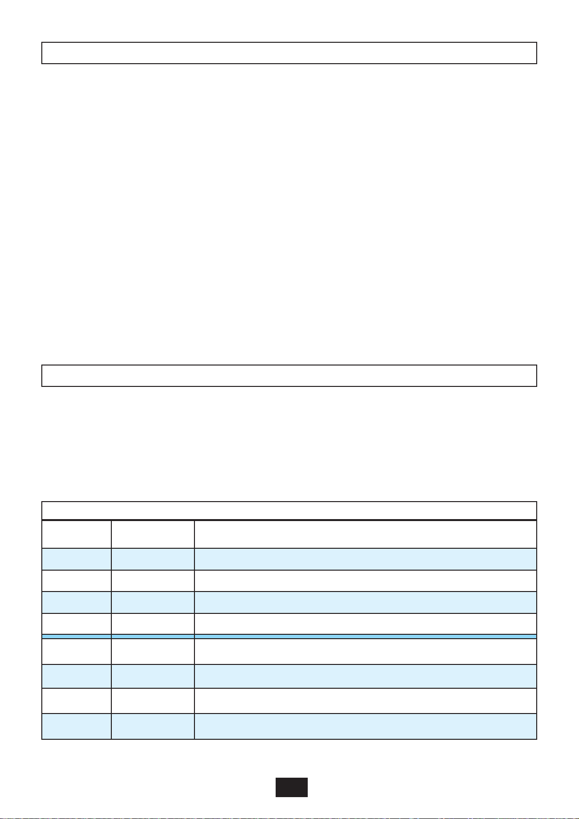
Pertes de charge au Circuit Primaire (CHAUDIERE)
0
1
2
3
4
5
6
7
8
9
10
0,5 1 1,5 2 2,5 3
Débit au Circuit Primaire (m3/h)
Pertes de charge (mCE)
25 kW
40 kW
60 kW
90 kW
Head loss on the primary circuit (BOILER)
Head loss (mWC)
Primary circuit flow rate (m3/h)
TECHNICAL DATA
Head loss on the primary circuit (BOILER)
Head loss (mWC)
Primary circuit flow rate (m3/h)
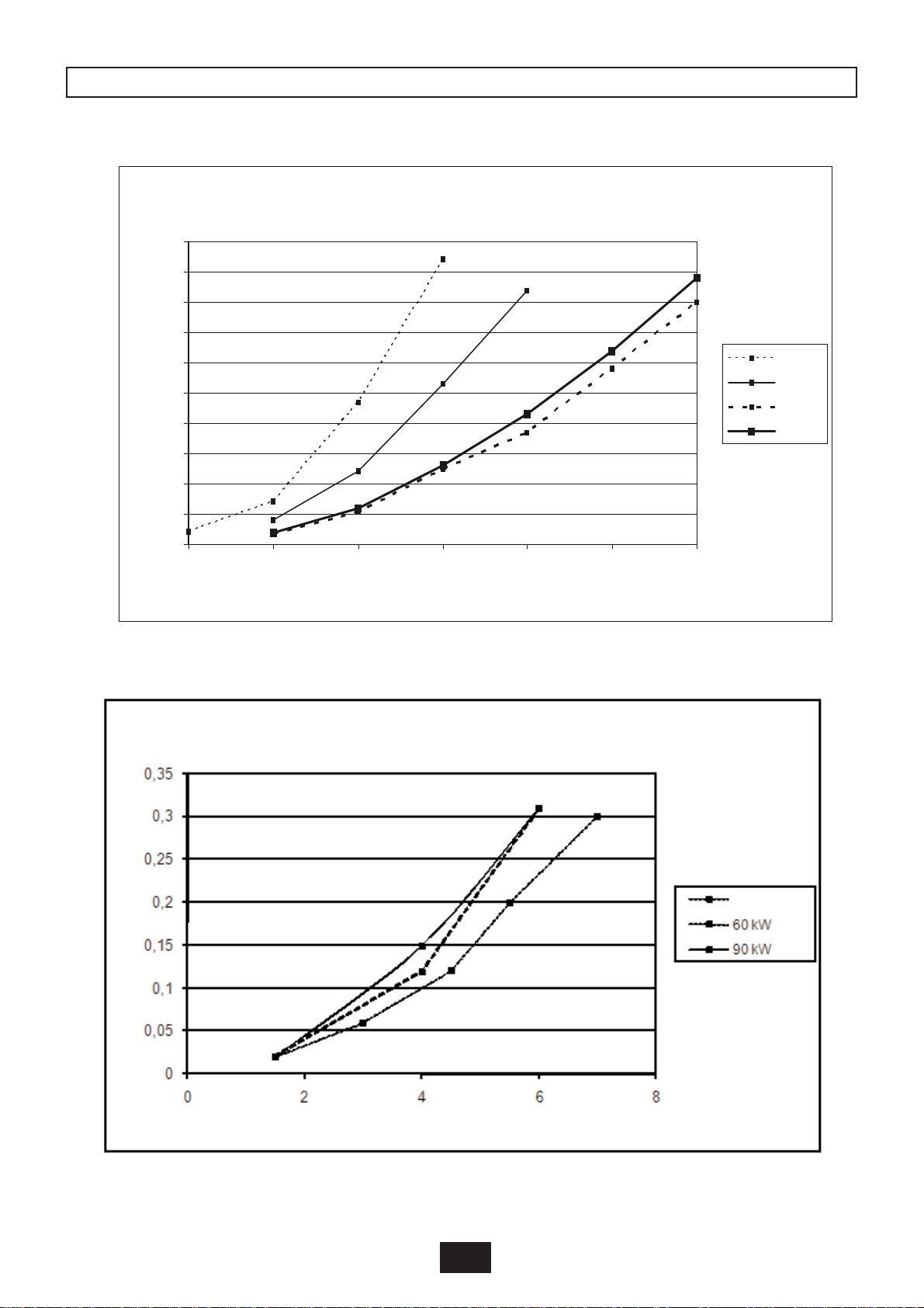
Head loss on the secondary circuit (POOL)
Head loss (mWC)
Secondary circuit flow rate (m3/h)
25 and 40 kW

19/48
2009/02 - Indice de révision : I - Code : 0033035
- Heat exchanger CLIMEXEL 25 kW -
Power output as a function of the boiler and pool
water temperatures
Temperature BOILER (°C)
Power (in kW)
pool water at 10°C
pool water at 20°C
pool water at 30°C
- Heat exchanger CLIMEXEL 40 kW -
Power output as a function of the boiler and pool
water temperatures
Temperature BOILER (°C)
Power (in kW)
pool water at 10°C
pool water at 20°C
pool water at 30°C

20/48
2009/02 - Indice de révision : I - Code : 0033035
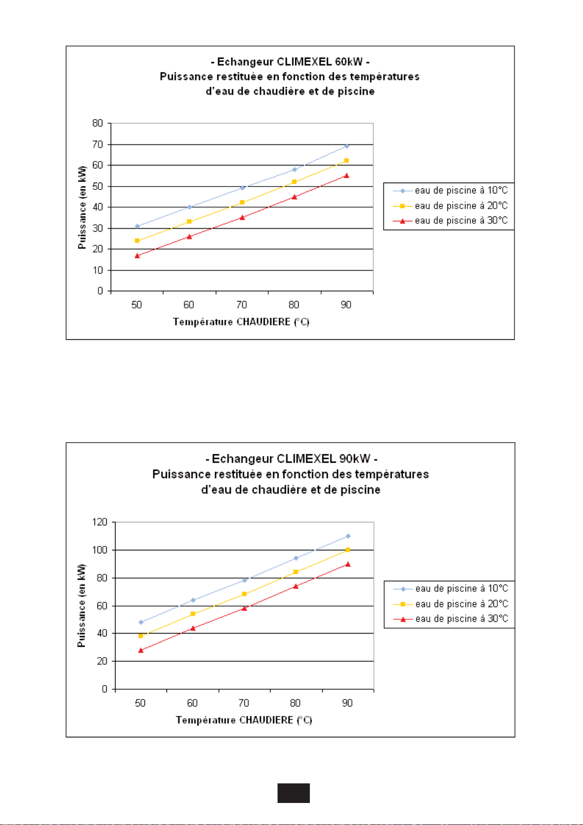
- Heat exchanger CLIMEXEL 60 kW -
Power output as a function of the boiler and pool
water temperatures
Temperature BOILER (°C)
Power (in kW)
pool water at 10°C
pool water at 20°C
pool water at 30°C
- Heat exchanger CLIMEXEL 90 kW -
Power output as a function of the boiler and pool water
temperatures
Temperature BOILER (°C)
Power (in kW)
pool water at 10°C
pool water at 20°C
pool water at 30°C
This manual suits for next models
15
Table of contents
Languages:


