prodelin 3.8M User manual

4096-535
Revision J
May 13, 2002
ASSEMBLY MANUAL
3.8M C-BAND Rx/Tx
ANTENNA SYSTEM
PRODELIN CORPORATION
1500 Prodelin Drive
Newton NC 28658

4096-535
PRODELIN CORPORATION 3.8M C-BAND Rx/Tx ANTENNA SYSTEM
3.8M C-BAND Rx/Tx
ANTENNA SYSTEM
J Revised Added 0168-260 Spacers 10/7/04
H Revise Labeling Text 5/13/02 RAH
G Revised Address 1/22/02 RAH
F Revise Figure 8 page 29 10-6-00 RAH
E Revise Part Numbers Page 9 6-21-00 RF
D Revised to delete Ku-Band features 12-10-98 RF
C Revised for locations of Labels - ECN2393 09-10-98 PGW
B Revised Elevation Rod to 0181-187 - ECN2367 04-28-98 PGW
A Revised pages 11, 14, 16, 18 for clarity 03-17-98 PGW
- ORIGINAL ISSUE 12/17/97 PGW
REV. DESCRIPTION DATE APPROVED

4096-535
PRODELIN CORPORATION 3.8M C-BAND Rx/Tx ANTENNA SYSTEM
1
3.8 METER C-BAND Rx/Tx ANTENNA SYSTEM
TABLE OF CONTENTS
SECTION TITLE
I GENERAL INFORMATION
1.0 INTRODUCTION
1.1 UNPACKING AND INSPECTION
1.2 MECHANICAL INSTALLATION TOOLS
1.3 SITE SELECTION
II MAST AND FOUNDATION
2.0 IN-GROUND MAST
2.1 PEDESTAL FOUNDATION
III REFLECTOR AND SUPPORT ASSEMBLY
3.0 PART LIST
3.1 AZ/EL POSITIONER INSTALLATION
3.2 REFLECTOR QUADRANT ORIENTATION
3.3 REFLECTOR SUPPORT ASSEMBLY
IV FEED SUPPORT ASSEMBLY
4.0 PART LIST
4.1 FEED SUPPORT INSTALLATION
4.2 C-BAND CROSS-POL & CO-POL FEEDS
4.3 C-BAND CIRCULAR POLARIZED FEED INST. (1.09 VAR )
4.4 C-BAND CIRCULAR POLARIZED FEED INST. (1.3 VAR )
4.5 C-BAND LNB / LNA ATTACHMENT
V ANTENNA POINTING
5.0 ALIGNMENT TO SATELLITE
5.1 INITIAL ALIGNMENT
VI MAINTENANCE
6.0 MAINTENANCE OVERVIEW
6.1 PERIODIC INSPECTION
6.2 REFLECTOR
6.3 MOUNT & REFLECTOR SUPPORT STRUCTURE
6.4 FEED & FEED SUPPORT

4096-535
PRODELIN CORPORATION 3.8M C-BAND Rx/Tx ANTENNA SYSTEM
2

4096-535
PRODELIN CORPORATION 3.8M C-BAND Rx/Tx ANTENNA SYSTEM
3
SECTION I GENERAL INFORMATION
1.0 INTRODUCTION
This manual describes the assembly and installation of Prodelin's 3.8M C-Band
Rx/Tx antenna system The Prodelin 3.8M is a rugged, reliable antenna system
that will operate at C-band frequencies with high efficiency and at the same time
successfully withstand the effects of the environment.
These instructions are listed by sections that cover all areas of assembly and
installation. Additional sections are included in the manual to provide information
on antenna alignment to the satellite and maintenance.
1.1 UNPACKING AND INSPECTION
1. UNPACKING & INSPECTION - The antenna containers should be
unpacked and inspected at the earliest date to ensure that all material has
been received and is in good condition. A complete packing list for each
major component is supplied.
CAUTION: DO NOT DRAG REFLECTOR SUPPORT FRAME ON THE
ADJUSTMENT THREAD RODS AS THESE ARE FACTORY SET AND
MUST NOT BE ALTERED!!
2. FREIGHT DAMAGE - Any damage to materials while in transit should be
immediately directed to the freight carrier. He will instruct you on the
matters regarding any freight damage claims.
3. MATERIAL - MISSING OR DAMAGED - Any questions regarding missing
or damaged materials that is not due to freight carrier should be directed
to Prodelin's Customer Service Department at:
PRODELIN CORPORATION
1500 Prodelin Drive
Newton NC 28658
USA
(828) 464-4141

4096-535
PRODELIN CORPORATION 3.8M C-BAND Rx/Tx ANTENNA SYSTEM
4
1.2 MECHANICAL INSTALLATION TOOLS
HARDWARE SIZE SAE WRENCH
SIZE METRIC WRENCH
SIZE MAXIMUM REC.
TORQUE
1 / 4” 7 / 16” 11 mm 80 in-lbs
5 / 16” 1 / 2” 13 mm 140 in-lbs
3 / 8” 9/16” 14 mm 20 ft-lbs
1 / 2” 3 / 4” 20 mm 45 ft-lbs
3 / 4” 1 – 1 / 8” 28 mm 140 ft-lbs
7 / 8” 1 – 1 / 4” 32 mm N / A
1” 1 – 1 / 2” 38 mm 220 ft-lbs
Also recommended for installation:
Adjustable Crescent Wrench 10”
Ratchet (3 / 8” & 1 / 2” Drive)
3” Wrench ( socket, crescent or pipe) for 2” bolt
Allen Wrench, 5/32”
Screw Driver ( standard and cross blade)
Inclinometer
Compass
Step Ladder
1.3 SITE SELECTION
In order to achieve maximum performance of your antenna system, it is important
to select the correct location for the antenna. The following guidelines should be
observed when selecting a site for the installation.
1. The line of site to the satellite should be clear of any obstructions, such as
trees or buildings.
2. The site should be relatively flat and level for ease of installation and
access to the antenna.
3. The site should be checked for underground obstruction, such as buried
cables or pipes.
4. All local building codes should be adhered to (i.e. grounding, foundation
requirements, zoning rules, setbacks, etc.).

4096-535
PRODELIN CORPORATION 3.8M C-BAND Rx/Tx ANTENNA SYSTEM
5
SECTION II SUGGESTED MAST AND FOUNDATIONS
NOTE: Due to the wide variety of soil conditions, Prodelin Corporation does not warrant that
any particular design or size of foundation is appropriate for any locality or earth station
installation. It is the responsibility of the installer/user to determine if it meets the site/locality
requirements. If there is any doubt, have it checked by an architect or structural engineer.
2.0 IN-GROUND MAST MOUNT
Figure 1 shows a suggested In-Ground Mast. The pipe is a 15 ft. length of 10"
schedule 40. Due to the high cost of shipping, Prodelin recommends site
procurement. Note that the Az/El Positioner Interface is a Slip Flange, which is
included with the antenna.
2.1 PEDESTAL FOUNDATION
Figure 2 shows a suggested Pad Foundation and figure 3 shows a suggested
Pier Foundation. Both foundations utilize Prodelin's Pedestal Mount. To install
the Pedestal Mount foundation, follow the steps below.
1. Install one [1] 1-8 hex nut and one [1] 1" flatwasher (items 2,3) onto the anchor
rod (item 5), then insert the anchor rod into one of the holes in the plywood
template (item 6) and install another 1-8 hex nut and 1" flatwasher. Repeat this
procedure for the remaining anchor rods. This will keep all the anchor rods in the
straight and proper orientation when the concrete is poured. Next, install two [2]
1-8 hex nuts and one [1] flatwasher (items 2,3) on the other end of each anchor
rod. See following pad layout and figures 2 & 3.
2. Once the site location is determined, dig up the area where the foundation will be
installed. Be careful not to dig too deep because the soil in the bottom and sides
of the foundation should be undisturbed. Position the reinforcing bars as shown.
Position the anchor rods so that the flatwashers are positioned under the
reinforcing bars. Pour concrete and allow to dry for 24 hours.
3. Once the concrete is dry, remove the plywood template and screw the lower hex
nuts as far down on the anchor rods as possible. Then install the mast pipe (item
1) on to the anchor rods. Adjust the lower hex nuts until the mast pipe is level in
the vertical position. Reinstall the flatwashers, lockwashers and hex nuts. With
the mast pipe tightened down, fill the space between the concrete slab and the
mast pipe base with grout.

4096-535
PRODELIN CORPORATION 3.8M C-BAND Rx/Tx ANTENNA SYSTEM
6
IN-GROUND MAST MOUNT
NOTES:
1. 2 x 2 x 1/4 HRS ANGLE & 10" SCHEDULE 40 PIPE SHOULD CONFORM WITH ASTM A36
STRUCTURAL STEEL.
2. ALL CONCRETE SHOULD CONFORM TO BUILDING CODE STANDARDS AND HAVE A MINIMUM
COMPRESSIVE STRENGTH OF 3000 PSI AT 28 DAYS. (PER ACI-318-77)
3. SOIL BEARING CAPACITY SHOULD BE NO LESS THAN 2000 PSF.
4. CONCRETE SHOULD BE POURED AGAINST UNDISTURBED SOIL.
5. ALLOW CONCRETE 24 HOUR SET TIME BEFORE INSTALLATION OF ANTENNA.
6. THE ANTENNA SHOULD BE PROPERLY GROUNDED TO MEET APPLICABLE LOCAL CODES.
7. MINIMUM DEPTH AS SHOWN OR EXTENDED TO LOCAL FROST LINE.
(PRODELIN CORP. DOES NOT REPRESENT OR WARRANT THAT ANY PARTICULAR DESIGN OR SIZE
OF FOUNDATION IS APPROPRIATE FOR ANY LOCALITY OR EARTH STATION INSTALLATION.)
5.50
60.0
.4
2 - 5 2 PL
AA
36.0
120.0
SEE NOTE #7
30.0
SECTION A-A 2 x 2 1/4 HRS ANGLE
24 INCHES LONG
TYPICAL 2 PLACES
SLIP FLANGE
(0156-898)
10” SCH 40 PIPE
(10.75 O.D.)
ESTIMATE 2 YARDS CONCRETE
Figure 1.

4096-535
PRODELIN CORPORATION 3.8M C-BAND Rx/Tx ANTENNA SYSTEM
7
PEDESTAL FOUNDATIONS
FOUNDATION PART LIST
ITEM NO. PART NO. DESCRIPTION QTY
1 0490-285 3.8M PEDESTAL MAST PIPE 1
2 8107-007 1-8 HEX NUT 32
3 8201-049 1" FLATWASHER 24
4 8202-046 1" LOCKWASHER 8
5 0180-238 1 - 8 X 36" ANCHOR ROD 8
6 0274-013 TEMPLATE, PLYWOOD 1
7.0”
96.0”
82.0”
7.0” 82.0”
96.0”
[ 6 ]
Remove before
installing Pedestal
Mount
[ 2, 3, 4, 5]
(7) #6 Bars. Equally
spaced both directions
Tie all rebar
intersections
with wire
PAD LAYOUT

4096-535
PRODELIN CORPORATION 3.8M C-BAND Rx/Tx ANTENNA SYSTEM
8
4.0”
3.0” MIN (TYP)
30.0”
[ 2, 3, 4 ]
[ 2, 3 ]
1-1/2” Grout Leveling
(if required)
27.0”
[ 1 ]
[ 5 ]
[ 2, 3, 2 ]
[ 1 ] [ 5 ]
[ 2, 3, 4 ]
[2, 3 ]
1-1/2” Grout Leveling
(if required)
4.0”
120.0”
27.0”
[ 2, 3, 2 ]
(6) #7 Bars. Equally
spaced both directions
#3 Ties @ 14”
center to cente
r
3000 PSI Concrete
30” DI
A
Figure 2.
Figure 3.

4096-535
PRODELIN CORPORATION 3.8M C-BAND Rx/Tx ANTENNA SYSTEM
9
SECTION III REFLECTOR AND SUPPORT ASSEMBLY
REFLECTOR AND SUPPORT ASSEMBLY PART LIST – TABLE 3.0
ITEM NO. PART NO. DESCRIPTION QTY
1 0159-273 THREADED INSERT - # 1 2
2 0159-272 THREADED INSERT - # 2 2
3 0159-276 THREADED INSERT - # 3 2
4 0159-271 THREADED INSERT - # 4 2
5 0159-275 THREADED INSERT - # 5 2
6 0159-274 THREADED INSERT - # 6 2
7 Varies REFLECTOR, QUADRANT # 1 1
8 Varies REFLECTOR, QUADRANT # 2 1
9 Varies REFLECTOR, QUADRANT # 3 1
10 Varies REFLECTOR, QUADRANT # 4 1
11 0181-262 Az/El POSITIONER ASSEMBLY 1
12 0181-485 CROSSARM ASSEMBLY 2
13 0181-486 SUPPORT FRAME ASSEMBLY 1
14 0181-187 ELEVATION ROD ASSEMBLY 1
15 8035-024 BOLT, 3/4 -10 x 3.00 12
16 8201-045 FLATWASHER, 3/4” 24
17 8202-045 LOCKWASHER, 3/4” 12
18 8106-002 NUT, HEX 3/4” 12
19 8201-052 FLATWASHER, 7/8” 12

4096-535
PRODELIN CORPORATION 3.8M C-BAND Rx/Tx ANTENNA SYSTEM
10
PART LIST - CONTINUED
ITEM NO. PART NO. DESCRIPTION QTY
20 8202-052 LOCKWASHER, 7/8” 12
21 8110-007 NUT, HEX 7/8” 12
22 8033-064 BOLT, 1/2 – 13 x 8.00 4
23 8033-072 BOLT, 1/2 – 13 x 9.00 4
24 8033-096 BOLT, 1/2 – 13 x 12.00 4
25 8201-033 FLATWASHER, 1/2” 12
26 8202-043 LOCKWASHER, 1/2” 12
27 0168-260 SPACER, 3.8M REFLECTOR LOCATOR 12
28 8032-014 BOLT, 3/8 – 16 x 1.75 32
29 8201-042 FLATWASHER, 3/8” 64
30 8202-042 LOCKWASHER, 3/8” 32
31 8102-007 NUT, HEX 3/8” 32
32 8036-016 BOLT, 1 – 8 x 2.00 2
33 8036-036 BOLT, 1 – 8 x 4.50 2
34 8036-040 BOLT, 1 – 8 x 5.00 2
35 8201-049 FLATWASHER, 1” 10
36 8202-046 LOCKWASHER, 1” 8
37 8107-007 NUT, HEX 1” 2
CAUTION: During the assembly procedure, the sequence of instructions must be
followed. Do Not Tighten Any Hardware Until Instructed. Refer to
the antenna assembly parts list and the following steps.
4096-535
PRODELIN CORPORATION 3.8M C-BAND Rx/Tx ANTENNA SYSTEM
11
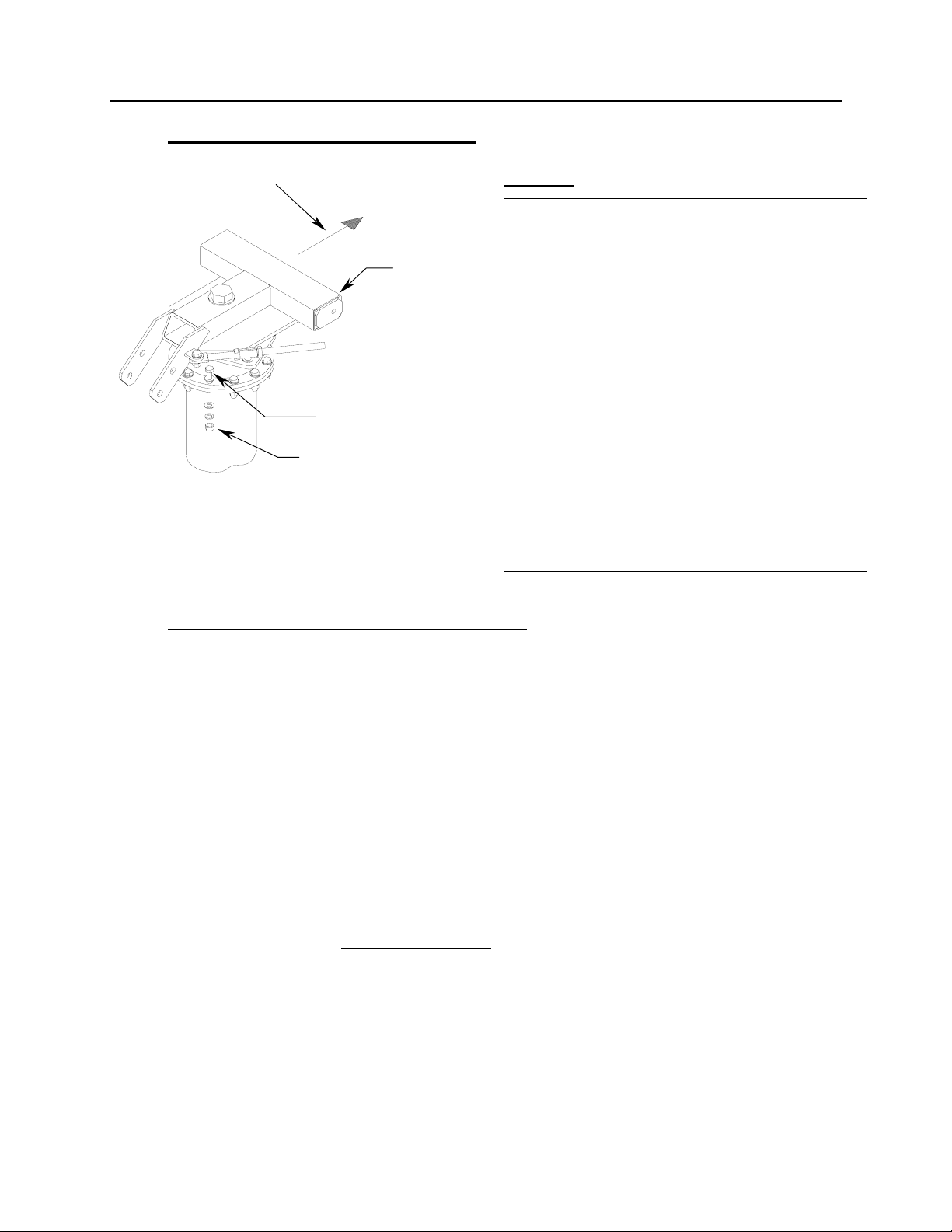
3.1 Az/El POSITIONER INSTALLATION
STEP 1:
3.2 REFLECTOR QUADRANT ORIENTATION
The 3.8M reflector quadrants can be assembled in either the standard or
inverted positions. The reflector quadrants are numbered 1, 2, 3 and 4. These
numbers can be found on the back of each quadrant embossed into the
fiberglass. Note that each quadrant has a longer side (major axis) and a shorter
side (minor axis). In the standard upright position, the antenna elevation angle
range is between 12 and 90 degrees. When viewed from behind in the standard
position (feed support at the bottom), quadrant #1 should be in the upper left; #2
is lower left; #3 is lower right and #4 in the upper right position. See Figure 4.
However, to allow a lower profile installation or in areas of high snow
accumulation, the reflector can be assembled in the inverted position (feed
support at the top). In this position, quadrant #1 would be in the lower right; #2
upper right; #3 in upper left and #4 in lower left position. See Figure 5.
Please note that it is not recommended to invert systems with the Anti-Ice
feature. The inverted assembly would prohibit proper heating element location.
A) Lift the Az/El positioner assembly
(item 11) on top of the pedestal mast
so that it rests upon the slip flange.
B) Rotate the positioner assembly towards
the desired azimuth heading as shown.
C) Once the position is located, rotate the
positioner in either direction to the
nearest set of holes. The result is a
coarse azimuth setting (+/- 30 deg.).
The fine azimuth setting will be set
later.
D) Secure the positioner to the pedestal
with 3/4” hardware (items 15,16,17,18).
Tighten Securely.
[ 16, 17, 18 ]
[ 15, 16 ]
Towards Desired
A
zimuth Headin
g
[ 11 ]

4096-535
PRODELIN CORPORATION 3.8M C-BAND Rx/Tx ANTENNA SYSTEM
12
14
23
1
4
2
3
Center Line
of Reflector
(Minor Axis)
Feed Rod Holes
Feed Support Holes
A
t Bottom
Ma
j
or Axis
Figure 4. (Standard)
Figure 5. (Inverted)
Feed Support Holes
A
t Top
Feed Rod Holes
Center Line
of Reflector
(Minor Axis)
Ma
j
or Axis

4096-535
PRODELIN CORPORATION 3.8M C-BAND Rx/Tx ANTENNA SYSTEM
13
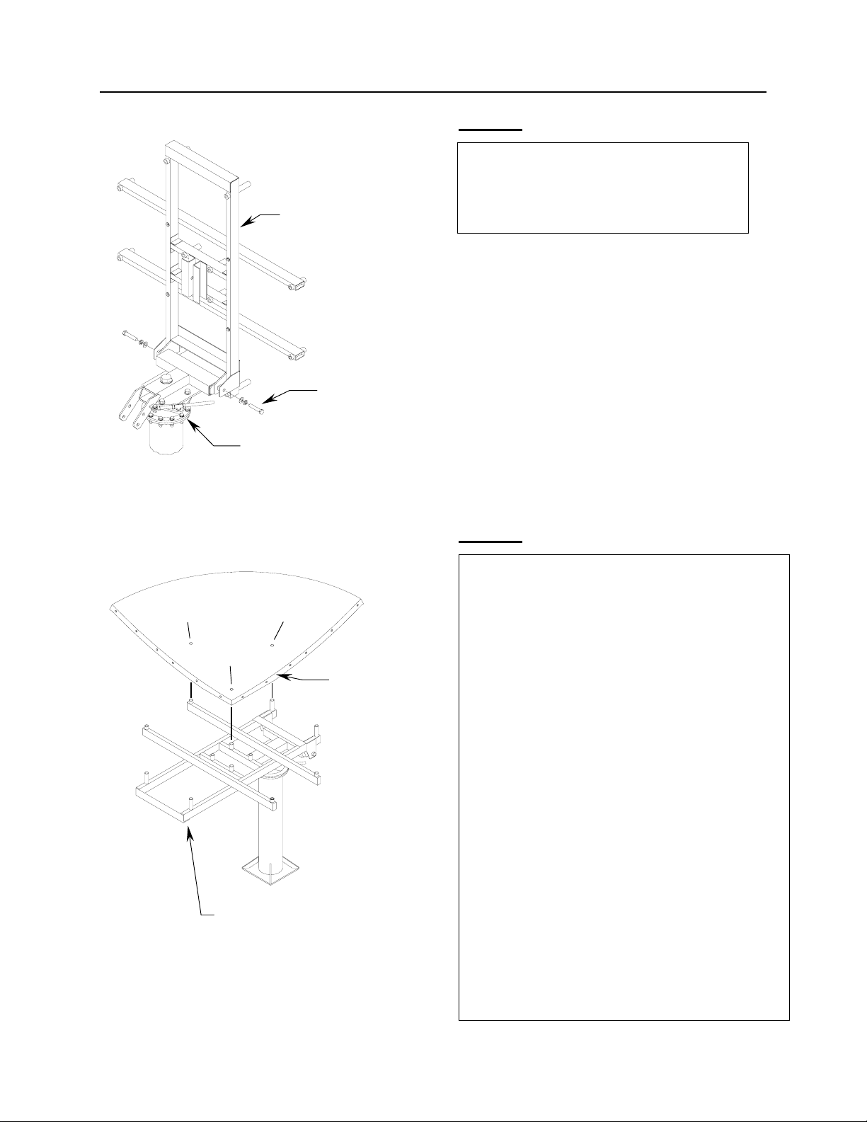
3.3 REFLECTOR SUPPORT ASSEMBLY
STEP 1:
WARNING! The reflector support frame includes a precision alignment feature. Do not drop or
drag the frame during the installation process. Do not attempt to adjust the round tube spacers
in the frame assembly, as these are factory pre-set. If these spacers are loose or damaged, or
there is any obvious damage to the frame, then you must obtain replacement parts for a
successful installation.
A) Before beginning antenna assembly.
Install 12 threaded inserts (items 1-6)
thru the face of each reflector quadrant.
Note that there are 6 different insert
lengths, 2 of each. Each insert must be
in the correct position in each quadrant
for correct assembly. The top of each
insert is stamped with a insert number
( 1 thru 6). The numbers shown in the
illustration correspond with the stamped
numbers on the inserts.
B) Secure inserts with 7/8” hardware
( items 19, 20, 21 ). Snug but do not
tighten.
Q 1
Q 4
Q 2
Q 3
5
6
3
3
5
6
11
4
2
4
2
[ 21 ]
Threaded Insert
[ 20 ]
[ 19 ]
Quadrant Face

4096-535
PRODELIN CORPORATION 3.8M C-BAND Rx/Tx ANTENNA SYSTEM
14
STEP 2:
STEP 3:
Locate the crossarms ( item 12 ) and
remove the 1/2” hardware &
anti-crushtubes.
1/2
Hardware
Crushtube
1/2 Bolt
Crossarm
A) Lay the support frame (item 13) on
a safe flat surface, being careful not
to damage the tube spacers.
B) Insert the anti-crushtubes into the 4
holes on the back of the frame as
shown.
C) Place each crossarm over the anti-
crushtubes and secure with the 1/2”
hardware removed in step 2. Make
sure label A of the support frame is
located with label A on the crossarm.
Repeat procedure with labels B,
C and D - See Detail A. Tighten
securely.
Note: Hardware should be
inserted from crossarm side.
Anti-
Crushtubes
(
both sides
)
Support Frame
Crossarms
Labels
Crossarm
Support Frame
Detail A
4096-535
PRODELIN CORPORATION 3.8M C-BAND Rx/Tx ANTENNA SYSTEM
15
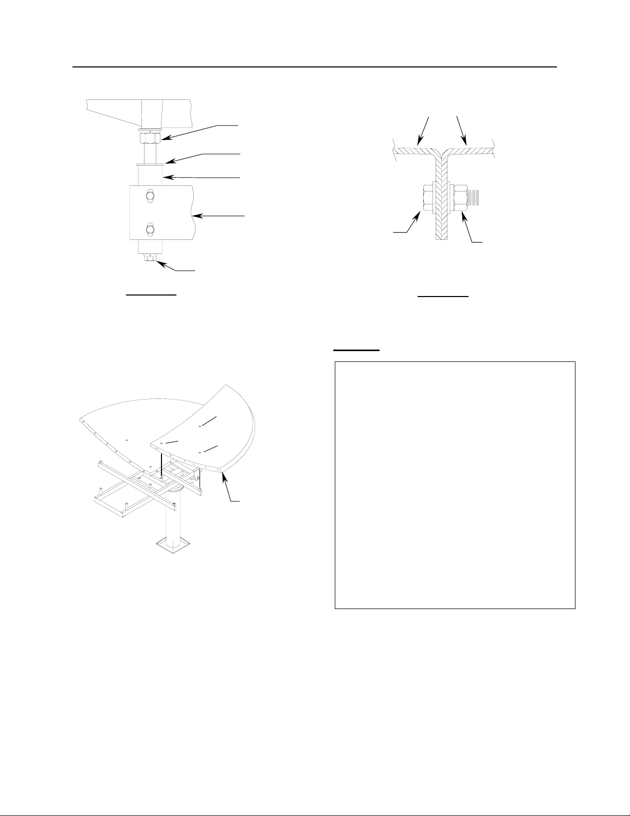
STEP 4:
STEP 5:
Lift the assembled support frame to
the Az/El positioner and secure with
1” hardware ( items 34, 35, 36 ). Lay
frame back to rest on positioner.
[ 34, 35, 36 ]
Both Sides
Positioner
Support Frame
A) Position quadrant 2 (quadrant 4 for
inverted) to the bottom left side of the
frame as shown. Note that it may be
necessary to loosen the 3 reflector
inserts to attain the proper alignment
with the 3 tubes in the support frame.
this procedure may occur with each of
the quadrants.
B) After the quadrant is in position,
place a spacer (item 27) between
each insert and tube (see Detail B).
repeat this procedure for all 4
quadrants.
C) Secure the quadrant to the frame with
1/2” hardware (Detail B ). Note that
there are 3 different 1/2” bolt lengths:
Location A = (items 23, 25, 26)
Location B = (items 22, 25, 26)
Location C = (items 24, 25, 26)
These locations are consistent with all
4 quadrants. Snug hardware only.
A
C
B
Quadrant 2
Support Frame
4096-535
PRODELIN CORPORATION 3.8M C-BAND Rx/Tx ANTENNA SYSTEM
16
STEP 6:
1/2” Hardware
Spacer
Insert
Tube
Frame
Quadrants
[28, 29 ] [ 29, 30, 31 ]
Detail B Detail C
A) Position quadrant 3 (quadrant 1 for
inverted) to the bottom right side of the
frame as shown.
B) Place Spacers as in step 5 and Detail
B.
C) Secure the quadrant to the frame with
1/2” hardware ( Detail B ). Note that
there are 3 different 1/2” bolt lengths:
Location A = (items 23, 25, 26)
Location B = (items 22, 25, 26)
Location C = (items 24, 25, 26)
D) Secure Quad 2 and 3 together with
3/8” hardware (items 28, 29, 30, 31)
See Detail C.
Quadrant 3
A
C
B

4096-535
PRODELIN CORPORATION 3.8M C-BAND Rx/Tx ANTENNA SYSTEM
17
STEP 7:
STEP 8:
A) Position quadrant 1 (quadrant 2 for
inverted) to the top left side of the
frame as shown.
B) Place Spacers as in step 5 and Detail
A.
C) Secure the quadrant to the frame with
1/2” hardware ( Detail B ). Note that
there are 3 different 1/2” bolt lengths:
Location A = (items 23, 25, 26)
Location B = (items 22, 25, 26)
Location C = (items 24, 25, 26)
D) Secure Quad 1 and 2 together with
3/8” hardware (items 28, 29, 30, 31)
See Detail C.
A) Position quadrant 4 (quadrant 3 for
inverted) to the top right side of the
frame as shown.
B) Place Spacers as in step 5 and Detail
A.
C) Secure the quadrant to the frame with
1/2” hardware ( Detail B ). Note that
there are 3 different 1/2” bolt lengths:
Location A = (items 23, 25, 26)
Location B = (items 22, 25, 26)
Location C = (items 24, 25, 26)
D) Secure Quad 4 to Quads 1 and 3 with
3/8” hardware (items 28, 29, 30, 31)
See Detail C.
E) At this time tighten all the 1/2”, 3/8” and
insert hardware alternating from one
side of a quadrant to another in a
circular pattern starting at the center
and working outward. Check the face of
the reflector while tightening to insure
all mating edges are flush.
C
B
A
A
C
B
Quadrant 4
Quadrant 1

4096-535
PRODELIN CORPORATION 3.8M C-BAND Rx/Tx ANTENNA SYSTEM
18
STEP 9:
STEP 10:
Locate the elevation rod (item 14) and
secure between the channels on the
support frame with 1” hardware
(items 34, 35, 36, 37)
[ 34, 35 ]
Channel
Elevation Rod
[ 35, 36, 37 ]
Support Frame
A) Loosen the nuts on the elevation
rod
so that the block has some freedom
to move.
B) Lift the support frame and position
the block between the tabs on the
positioner.
C) Secure Block with 1” hardware
(items 32, 35, 36). Tighten the 2”
nuts against the block.
Fine elevation adjustment will be
set later.
Elevation Rod
[ 32, 35, 36 ]
Block & Nuts
Tabs
[ 32, 35, 36 ]
Table of contents
Other prodelin Antenna manuals

prodelin
prodelin 1381 User manual

prodelin
prodelin 1132 series User manual

prodelin
prodelin 4096-247 User manual

prodelin
prodelin 1134 User manual

prodelin
prodelin 1251 User manual

prodelin
prodelin C-Band Rx/Tx User manual

prodelin
prodelin 1132 series User manual

prodelin
prodelin 1183 series User manual

prodelin
prodelin 1135 Series User manual

prodelin
prodelin TIER II User manual
Popular Antenna manuals by other brands


Johansson
Johansson 6550A instruction manual

Alcad
Alcad 900 Series manual

ZyXEL Communications
ZyXEL Communications ZYAIR EXT-109 - MOUNTING Mounting guide

Parsec Antennas
Parsec Antennas Chinook installation instructions

Philips
Philips SDV7114A user manual

impro
impro XTT901-1-0-GB Series installation manual


