prodelin 1251 User manual

4096-476
November 21, 1997
Revision B
Assembly Manual
2.4 METER
SERIES 1251 ANTENNA SYSTEM
PRODELIN CORPORATION
1700 NE CABLE DRIVE
CONOVER, NC 28613-0368

4096-476
PRODELIN CORPORATION 2.4M SERIES 1251
2
2.4 Meter 2 Piece Az/El
Installation Instructions
B Overall Update 11/21/97 PGW
A Revised Hdw tables to reflect B.O.M 2/11/97 PGW
- ORIGINAL RELEASE 4/10/96 RF
REV. DESCRIPTION DATE APPROVED

4096-476
PRODELIN CORPORATION 2.4M SERIES 1251
3
2.4M SERIES 1251 ANTENNA SYSTEM
TABLE OF CONTENTS
SECTION TITLE
I GENERAL INFORMATION
1.0 INTRODUCTION
1.1 UNPACKING AND INSPECTION
1.2 MECHANICAL INSTALLATION TOOLS
1.3 SITE SELECTION
1.4 SUGGESTED MAST & FOUNDATION
II REFLECTOR AND SUPPORT ASSEMBLY
2.0 PART LIST
2.1 AZ/EL POSITIONER INSTALLATION
2.2 REFLECTOR PETAL ORIENTATION
2.3 REFLECTOR SUPPORT ASSEMBLY
III FEED SUPPORT
3.0 PART LIST
3.1 FEED SUPPORT INSTALLATION
IV ANTENNA POINTING
4.0 ALIGNMENT TO SATELLITE
4.1 INITIAL ALIGNMENT
V MAINTENANCE
5.0 MAINTENANCE OVERVIEW
5.1 PERIODIC INSPECTION
5.2 REFLECTOR
5.3 MOUNT AND REFLECTOR SUPPORT
5.4 FEED AND FEED SUPPORT
4096-476
PRODELIN CORPORATION 2.4M SERIES 1251
4

4096-476
PRODELIN CORPORATION 2.4M SERIES 1251
5
SECTION I GENERAL INFORMATION
1.0 INTRODUCTION
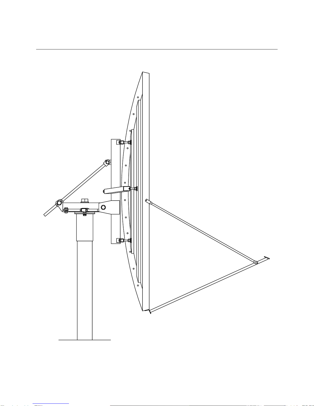
This manual describes the assembly and installation of Prodelin's 2.4M 2-Piece
Rx/Tx offset antenna system with an Az/El mount (series number1251). The
Prodelin 2.4M is a rugged, reliable antenna system that will operate at C-band
and Ku-band frequencies with high efficiency and at the same time successfully
withstand the effects of the environment.
These instructions are listed by sections that cover all areas of assembly and
installation. Additional sections are included in the manual to provide information
on antenna alignment to the satellite and maintenance.
1.1 UNPACKING AND INSPECTION
1. UNPACKING & INSPECTION - The antenna containers should be
unpacked and inspected at the earliest date to ensure that all material has
been received and is in good condition. A complete packing list for each
major component is supplied.
2. FREIGHT DAMAGE - Any damage to materials while in transit should be
immediately directed to the freight carrier. He will instruct you on the
matters regarding any freight damage claims.
3. MATERIAL - MISSING OR DAMAGED - Any questions regarding missing
or damaged materials that is not due to freight carrier should be directed
to Prodelin's Customer Service Department at:
PRODELIN CORPORATION
1700 NE CABLE DRIVE
P.O. BOX 368
CONOVER, NORTH CAROLINA 28613
USA
(828) 464-4141

4096-476
PRODELIN CORPORATION 2.4M SERIES 1251
6
1.2 MECHANICAL INSTALLATION TOOLS
HARDWARE SIZE SAE WRENCH
SIZE METRIC WRENCH
SIZE MAXIMUM REC.
TORQUE
3 / 8” 9/16” 14 mm 15 ft-lbs
1 / 2” 3 / 4” 20 mm 35 ft-lbs
5 / 8” 15 / 16” 24 mm 70 ft-lbs
3 / 4” 1 – 1 / 8” 28 mm 160 ft-lbs
1” 1 – 1 / 2” 38 mm 220 ft-lbs
Also recommended for installation:
Adjustable Wrench 10”
Ratchet (3 / 8”& 1 / 2”Drive)
3”Wrench ( socket, crescent or pipe) for 2”bolt
Inclinometer
Compass
1.3 SITE SELECTION
In order to achieve maximum performance of your antenna system, it is
important to select the correct location for the antenna. The following guidelines
should be observed when selecting a site for the installation.
1. The line of site to the satellite should be clear of any obstructions, such as
trees or buildings.
2. The site should be relatively flat and level for ease of installation and
access to the antenna.
3. The site should be checked for underground obstruction, such as buried
cables or pipes.
4. All local building codes should be adhered to (i.e. grounding, foundation
requirements, zoning rules, setbacks, etc.).
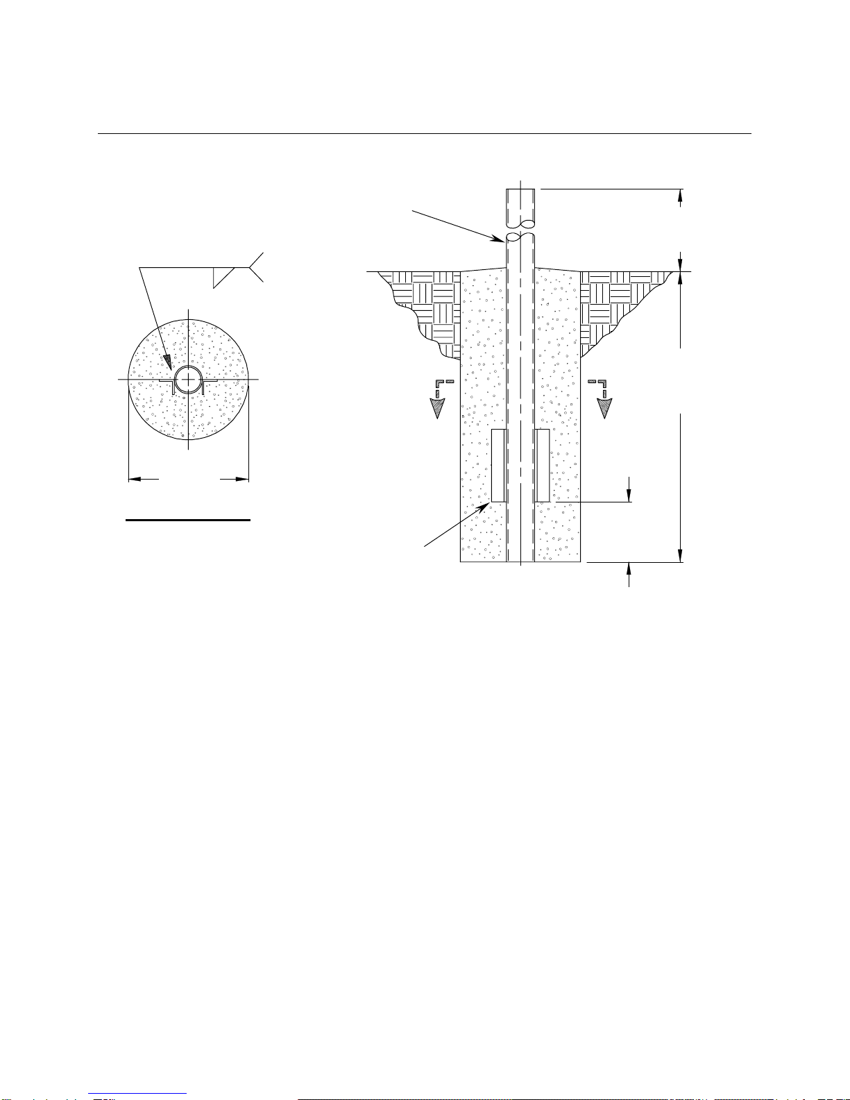
1.4 SUGGESTED MAST & FOUNDATION
4096-476
PRODELIN CORPORATION 2.4M SERIES 1251
7
NOTES:
1. 2 x 2 x 1/4 HRS Angle and schedule 40 pipe should conform with ASTM A36 and ASTM A53
Type E and S Grade B.
2. All concrete should conform to building code standards and have a
minimum compressive strength of 3000 PSI at 28 days. (Per ACI-318-77)
3. Soil bearing capacity should be no less than 2000 PSF.
4. Concrete should be poured against undisturbed soil.
5. Allow concrete 24 hours set time before installation of antenna.
6. The antenna should be properly grounded to meet applicable local codes.
7. Minimum depth as shown or extend to local frost line.
8. Foundation meets the design requirements as set forth by the uniform building code. (1982
edition)
(PRODELIN CORPORATION DOES NOT REPRESENT OR WARRANT THAT ANY PARTICULAR
DESIGN OR SIZE OF FOUNDATION IS APPROPRIATE FOR ANY LOCALITY OR EARTH STATION
INSTALLATION.)
54.0
54.0
SEE NOTE #7
A
A
12.0
24.0
2-5 TYP 2
SECTION A-A
2 x 2 1/4 HRS ANGLE
12 INCHES LONG
TYPICAL 2 PLACES
6”SCH 40 PIPE
(6.625”OD)
4096-476
PRODELIN CORPORATION 2.4M SERIES 1251
8
SECTION II REFLECTOR AND SUPPORT ASSEMBLY
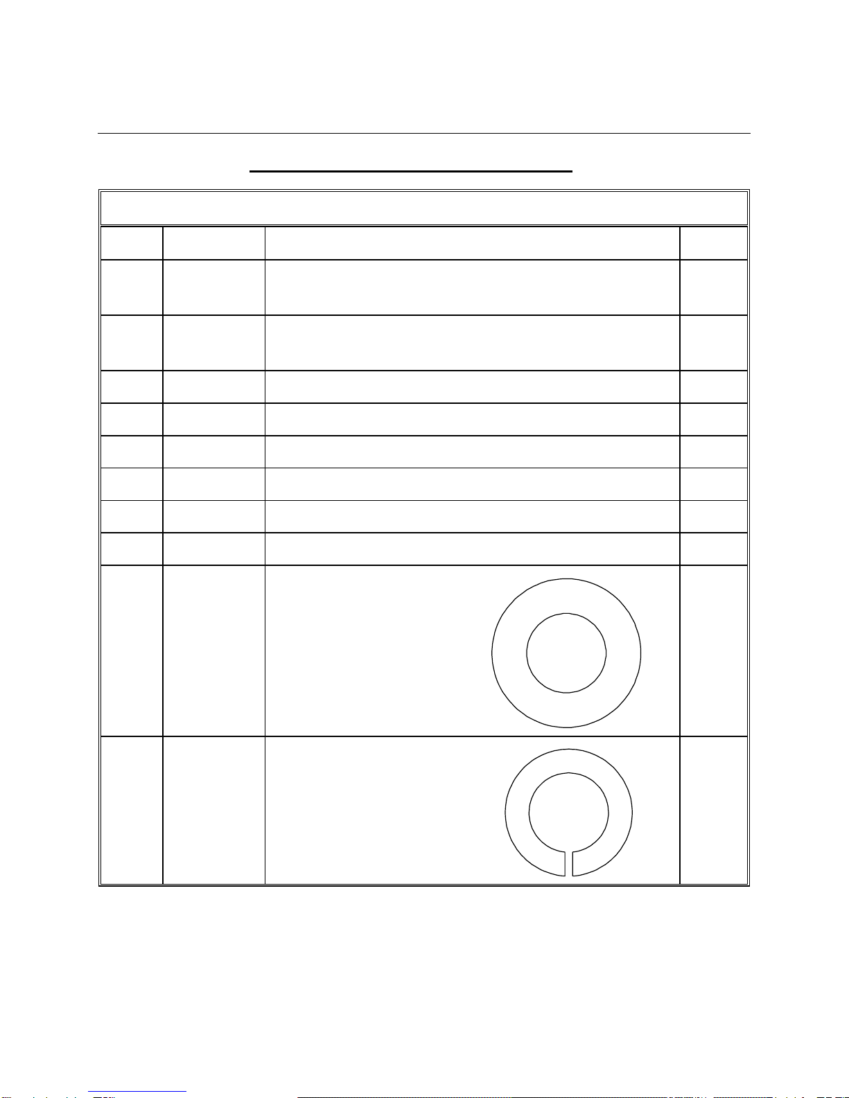
REFLECTOR AND SUPPORT ASSEMBLY PART LIST- TABLE 2.0
ITEM PART NO. DESCRIPTION QTY
1 0179-381
0179-383 REFLECTOR “A”SIDE
REFLECTOR “A”SIDE – WITH SHC 1
2 0179-382
0179-384 REFLECTOR “B”SIDE
REFLECTOR “B”SIDE – WITH SHC 1
3 0181-691 Az / El POSITIONER ASSEMBLY 1
4 0159-283 THREADED INSERT 6
5 0490-601 SUPPORT TUBE 1
6 0250-657 TOP / BOTTOM CROSSARM 2
7 0181-249 ELEVATION ADJUSTMENT ASSEMBLY 1
8 0490-602 CROSSARM WELDMENT 1
9 8201-045
6
10 8200-007
6
3/4 ”FLATWASHER
3/4”LOCK WASHER

4096-476
PRODELIN CORPORATION 2.4M SERIES 1251
9
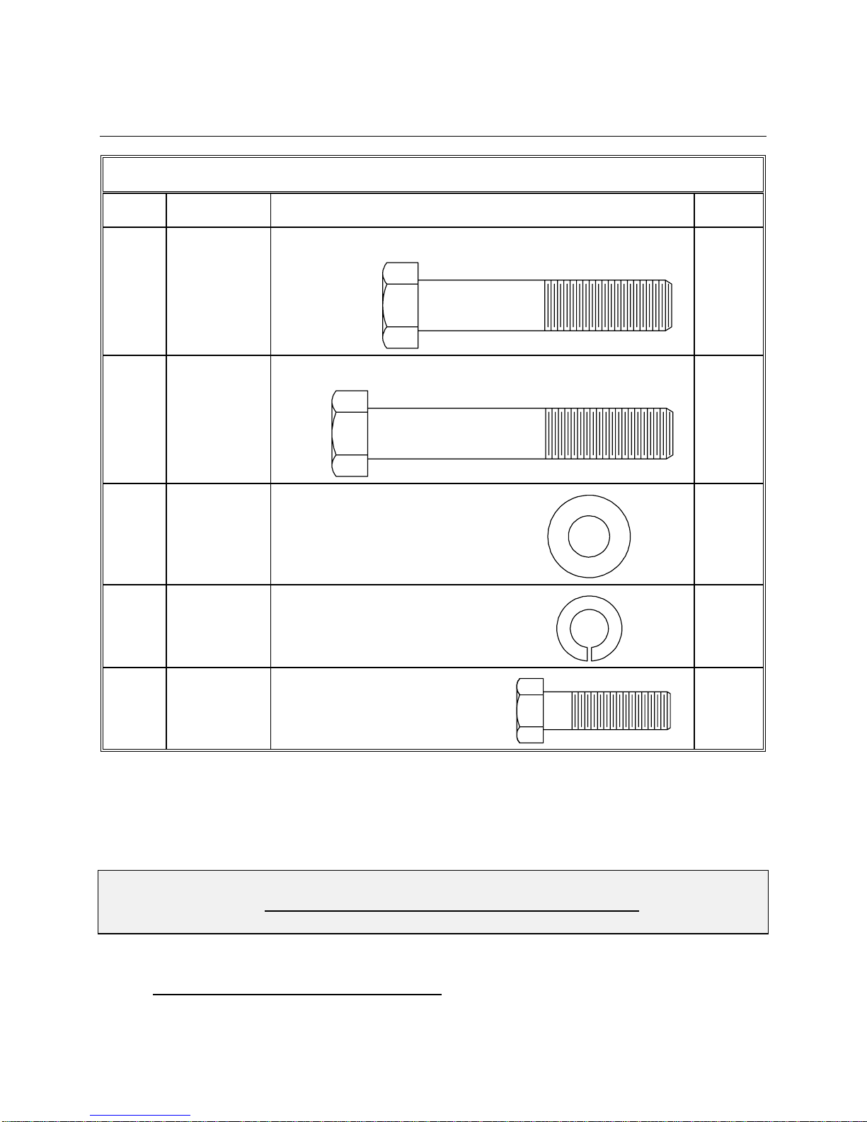
PARTS LIST - CONTINUED
ITEM PART NO. DESCRIPTION QTY
11 8106-007
6
12 8201-043
12
13 8201-030
28
14 8202-043
20
15 8104-007
20
16 8033-010
14
3/4”HEX NUT
1/2”FLATWASHER
1/2”FLATWASHER - NARROW
1/2”LOCK WASHER
1/2”HEX NUT
1/2”-13 x 1.25 BOLT
4096-476
PRODELIN CORPORATION 2.4M SERIES 1251
10
PARTS LIST - CONTINUED
ITEM PART NO. DESCRIPTION QTY
17 8033-021
4
18 8033-032
2
19 8201-042
6
20 8202-042
6
21 8032-010
6
CAUTION: During the assembly procedure, the sequence of instructions must be
followed. Do Not Tighten Any Hardware Until Instructed. Refer to
the antenna assemblyparts list and the following steps.
2.1 Az / El POSITIONER INSTALLATION
1/2”-13 x 2.50 BOLT
1/2”-13 x 4.00 BOLT
3/8”FLATWASHER
3/8”-16 x 1.25 HEX
3/8”LOCK WASHER

4096-476
PRODELIN CORPORATION 2.4M SERIES 1251
11
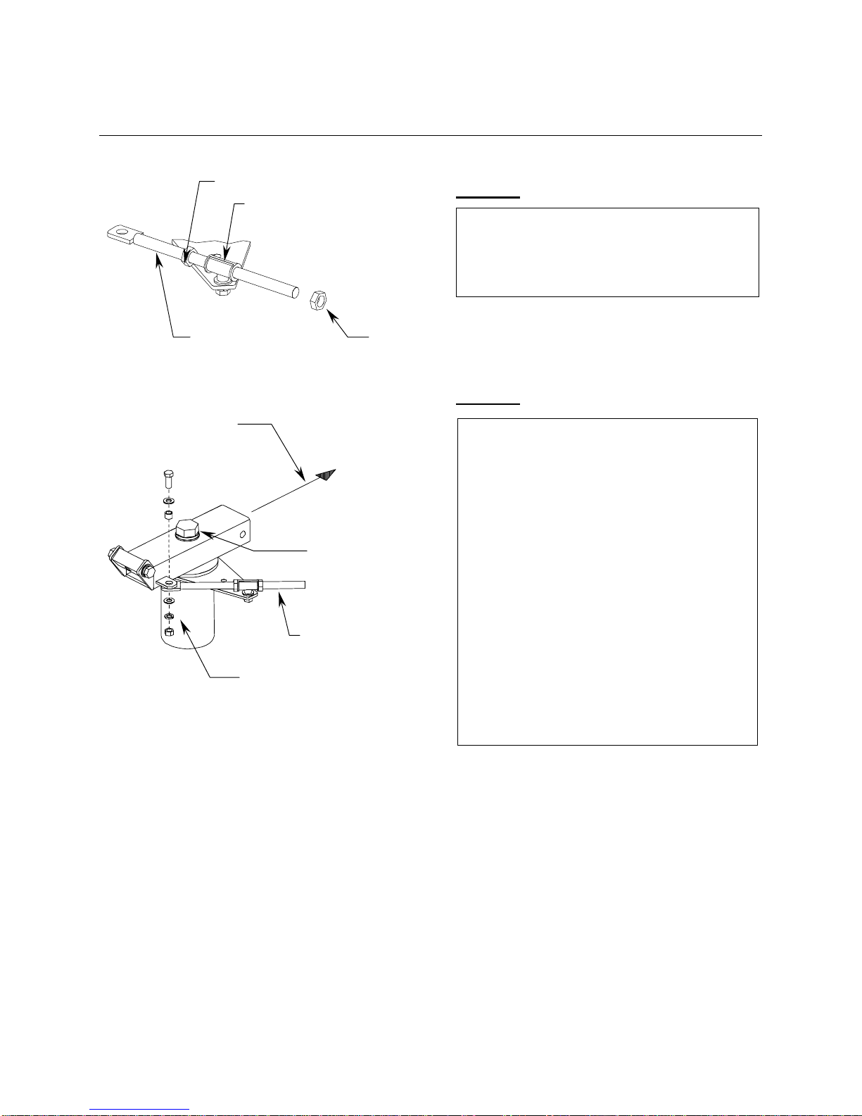
STEP 1:
STEP 2:
STEP 3:
Back out the [8] 5/8”set screws from the
canister and slip Az/El positioner assembly
over the mast pipe. Tighten the set screws
snug against the mast pipe.
Az/El Positioner Asm
5/8”Set Screws
Mast Pipe
A) Loosen the 2”rotation bolt on
top of the positioner.
A) Rotate the positioner so that
the canister plate is oriented as
shown.
C) Lightly tighten the 2”bolt.
90
2”Rotation Bol
t
A) Remove the azimuth rod from the
positioner.
A) Run one of the 1”nuts up towards
the tab end of the rod and remove
the other 1”nut.
Tab
Azimuth Rod
1”Nuts
4096-476
PRODELIN CORPORATION 2.4M SERIES 1251
12
STEP 4:
STEP 5:
Place the end of the azimuth rod thru
the adjustment tube attached to the
top of the canister plate and replace
the 1”hex nut.
Canister Plate
1”Hex nut
Adjustment Tube
Azimuth Rod
A) Re-attach the azimuth rod to the
positioner with the 3/4”x 2.00 bolt
flatwashers, lockwasher, sleeve
and nut. Tighten securely.
Snug the 2”rotation bolt at this
time.
A) The positioner must be oriented
correctly to the center of the
satellite orbital arc. Loosen the set
screws and rotate the canister on
the mast pipe to the required
position. Tighten the set screws
then tighten the 5/8”lock nuts
against the canister.
To Satellite
(
within 5 de
g
.
)
3/4”Hardware
Azimuth Rod
2”Bolt

4096-476
PRODELIN CORPORATION 2.4M SERIES 1251
13
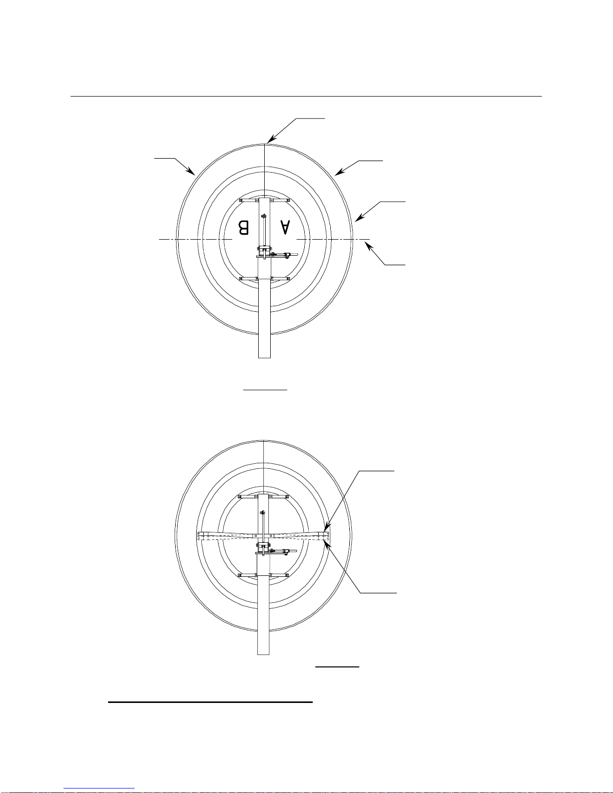
2.2 REFLECTOR PETAL ORIENTATION
The series 1251 reflector petals are labeled “A”and “B”. In the standard upright
position, the antenna elevation angle range is between 5 and 90 degrees. When
viewed from behind in the standard position (feed support at the bottom), the “A”
petal (item 1) is on the left side and the “B” petal (item 2) is on the right side –
See Fig. 1.
However, to achieve a lower profile installation or in areas of high snow
accumulation, the reflector can be assembled inverted (feed support on top)
with the “B”petal on the left side and the “A”petal on the right side – See Fig. 2.
Please note that in either situation, the angled cross arm (item 8) must be
oriented for the correct position – See Fig. 3.
Figure 1
“B” Petal
( item 2 )
“A” Petal
( item 1 )
Center of Reflector
Feed Rod Holes
Feed Support at Bottom
4096-476
PRODELIN CORPORATION 2.4M SERIES 1251
14
2.3 REFLECTOR SUPPORT ASSEMBLY
Figure 2
“B” Petal
( item 2 ) “A” Petal
( item 1 )
Center of Reflector
Feed Support on Top
Feed Rod Holes
Orientation of Angled
Crossarm for Standard
Position
Orientation of Angled
Crossarm for Inverted
Position
Figure 3

4096-476
PRODELIN CORPORATION 2.4M SERIES 1251
15
STEP 1:
STEP 2:
STEP 3:
Place three of the threaded inserts
(item 4) thru the face of each reflector
petal (items 1& 2) and secure with 3/4”
hardware (items 9, 10 & 11). Snug
only, Do not completely tighten at this
time.
[ 4 ]
[ 9, 10, 11 ]
Reflector
Petal
A) Remove the 1”bolt and hardware from
the Az/El positioner.
B) Straddle the tabs of the reflector
tube (item 5)over the holes in the
positioner and replace 1”bolt and
hardware. Tighten snug only and let
the tube fall back upon the positioner.
1”Bolt
[ 5 ]
Positioner
1”Hardware
[12, 14, 15 ] 4 PL
4096-476
PRODELIN CORPORATION 2.4M SERIES 1251
16
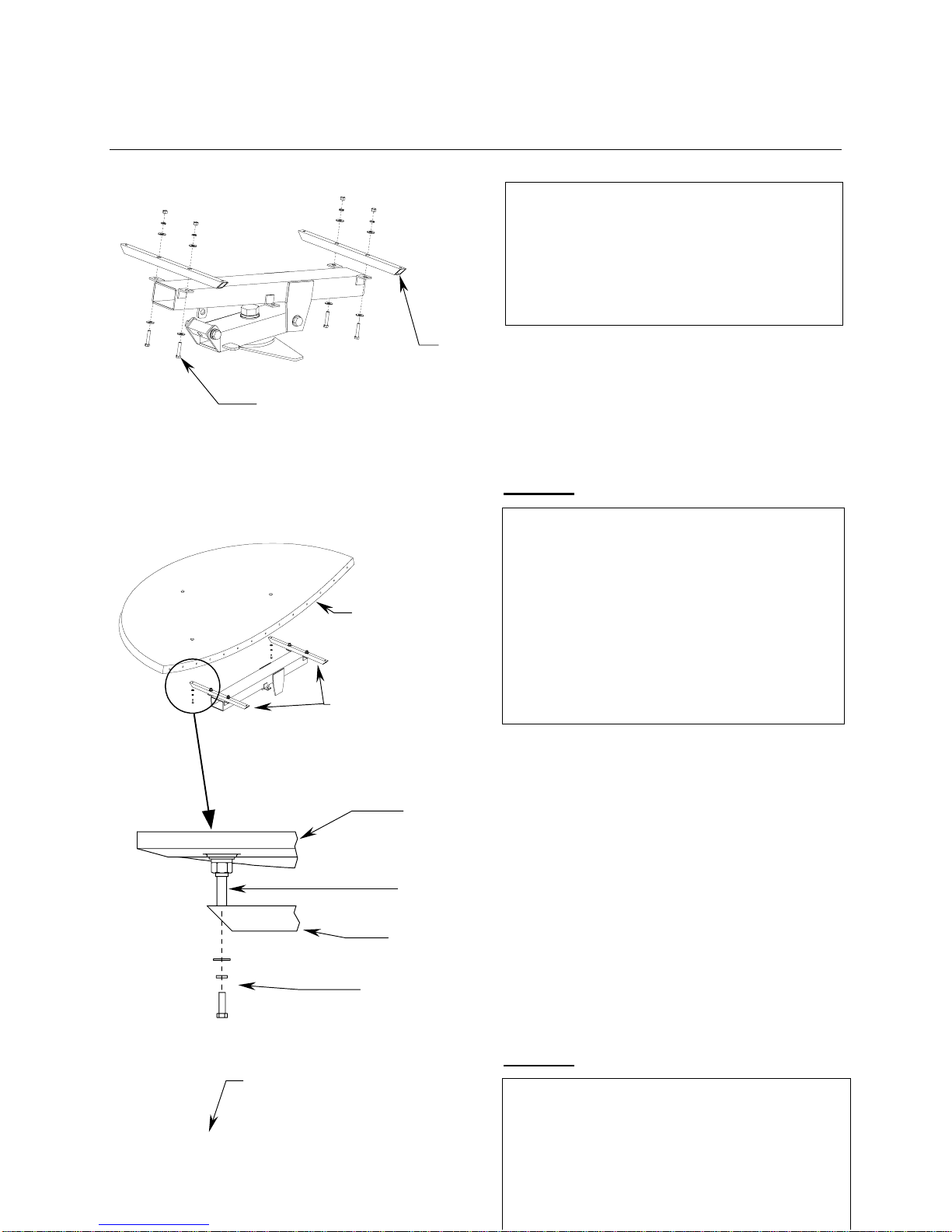
STEP 4:
STEP 5:
Attach the top and bottom crossarms
(item 6) to the reflector support tube
with 1/2”hardware (items
12,14,15,17).
Note orientation of crossarms.
Do not tighten.
[ 6 ] 2 PL
[ 17, 12 ] 4 PL
A) Place one reflector petal onto the
Cross arms in either the standard or
inverted position – see 2.2. Attach
with 3/8”hardware (items 19,20,21)
at each crossarm. Do not tighten
B) Place the second reflector petal on
the cross arms and repeat above
procedure.
Reflector
Petal
Crossarms
Reflector Petal
Insert
Crossarm
[ 19, 20, 21 ]
Attach the two petals together with 1/2”
hardware (items 13, 14, 15, 16) at the
fourteen holes on the inner seams of
the reflector petals.
Tighten these bolts securely at this time
while aligning the petals at the face of
the reflector.
Check for best
Petal Alignment
4096-476
PRODELIN CORPORATION 2.4M SERIES 1251
17
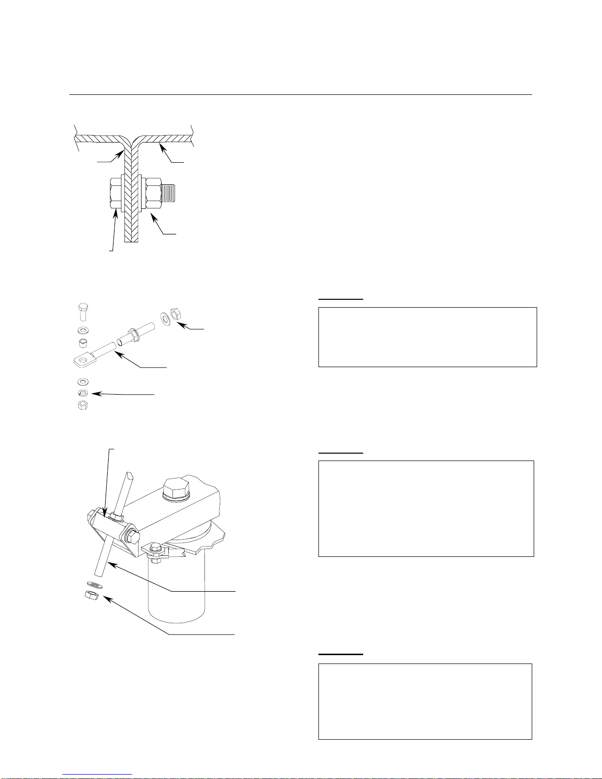
STEP 6:
STEP 7:
STEP 8:
[ 13, 14, 15 ]
[ 16,13 ]
Petal
Petal
Locate the elevation assembly (item 7)
and remove the 3/4”hardware as well
as one 1”hex nut and washer.
1”Hex Nut
&
Flatwasher
3/4”Hardware
[ 7 ]
Carefully swing the reflector up into
a vertical position. Insert the elevation
assembly (item 7) thru the elevation
adjustment tube at the back of the
positioner. Replace the 1”hex nut and
flatwasher.
1”Hex Nut & Flatwasher
Elevation Assembly
Adjustment Tube
Attach tabbed end of the elevation
assembly to the tab on the back of
the reflector support tube with the
3/4”hardware removed in step 6.
Tighten securely.

4096-476
PRODELIN CORPORATION 2.4M SERIES 1251
18
STEP 9:
SECTION III FEED SUPPORT ASSEMBLY
3/4”Hardware
Support Tube
Elevation
Assembly
A) Attach the angled crossarm
(item 8) to the reflector support
tube in either the standard or
inverted position depending on
the reflector orientation with 1/2”
hardware (items 12, 14, 15, 18).
A) Attach the ends of the crossarm
to the reflector petals at the
threaded inserts with 3/8”hard-
ware (items 19, 20, 21).
A) Tighten the reflector support
hardware by first tightening the
3/4”hardware at the six reflector
inserts followed by the 3/8”bolts
holding the reflector to the three
crossarms. Next tighten six 1/2”
bolts holding the crossarms to
the reflector support tube.
Do not tighten the elevation
hardware until after satellite
alignment.
[ 12, 14, 15 ]
[ 19,20,21]
[
8
]
[ 18, 12 ]
[ 19, 20, 21 ]
Support Tube

4096-476
PRODELIN CORPORATION 2.4M SERIES 1251
19
The following instructions are for installing a typical C-band or Ku-band feed support to
Prodelin's 2.4 meter antenna system.
FEED SUPPORT PART LIST- TABLE 3.0
ITEM PART NO. DESCRIPTION QTY
1 VARIES FEED SUPPORT 1
2 VARIES FEED ROD – Ku BAND 2
3 VARIES FEED ROD – C BAND 2
4 8032-014
4
5 8032-028 3/8”x 4.00 BOLT 1
6 8201-042 3/8”FLATWASHER
10
7 8202-042 3/8”LOCKWASHER
5
8 8102-007 3/8”HEX NUT
5
3.1 Feed Support Installation
STEP 1:
3/8”x 1.75 BOLT

4096-476
PRODELIN CORPORATION 2.4M SERIES 1251
20
STEP 2:
STEP 3:
Attach the feed rods loosely to the
reflector with 3/8”hardware (items-
4, 6, 7 & 8 ). See detail A
Feed Rods
See Detail A
Position the feed support in front of the
reflector and attach to the ends of the
two feed rods with 3/8”hardware
( items 5, 6, 7 & 8 ). See Detail B.
Do not tighten.
See Detail B
Feed Support Tube
Table of contents
Other prodelin Antenna manuals

prodelin
prodelin 1135 Series User manual

prodelin
prodelin TIER II User manual

prodelin
prodelin 1134 User manual

prodelin
prodelin 3.8M User manual

prodelin
prodelin 1132 series User manual

prodelin
prodelin 1381 User manual

prodelin
prodelin C-Band Rx/Tx User manual

prodelin
prodelin 4096-247 User manual

prodelin
prodelin 1183 series User manual

prodelin
prodelin 1132 series User manual
Popular Antenna manuals by other brands


DX Engineering
DX Engineering DXE-4030VA-1 manual

BAS
BAS WiFiAgent Quick user guide

M2 Antenna Systems
M2 Antenna Systems 40M3C manual

Hirschmann Car Communication
Hirschmann Car Communication HCEL-AG-0184B-01 installation instructions

One Forall
One Forall SV-9453 instruction manual

CCOM
CCOM iNetVu 755 troubleshooting guide


