Production Basics 1000-1711 User manual
Production Basics, Inc. Massachusetts, USA 800.318.2770 617.926.8100 Fax: 617.926.8010 www.pbasics.com
ASSEMBLY MANUAL
ASSEMBLY VIDEOS AVAILABLE ON-LINE http://video.pbasics.com
PARTS AND HARDWARE QUANTITY
30”D
worksurface
36” D
worksurface
Height Adjustable C-Legs (2 pieces each) 2 2
Frame 1 1
Worksurface Support Rails 2 3
Top Brackets 2 2
Worksurface 1 1
Leveling Feet
6 6
End Caps 8 8
Wood Screws 8 12
Tek Screws 6 8
Basic Nuts 8 10
Basic Bolts 12 14
7/32 Allen Wrench 1 1
Casters (if ordered) 4 4
Other Items Needed (not included)
Phillips head screwdriver or drill
Rubber Mallet
Level
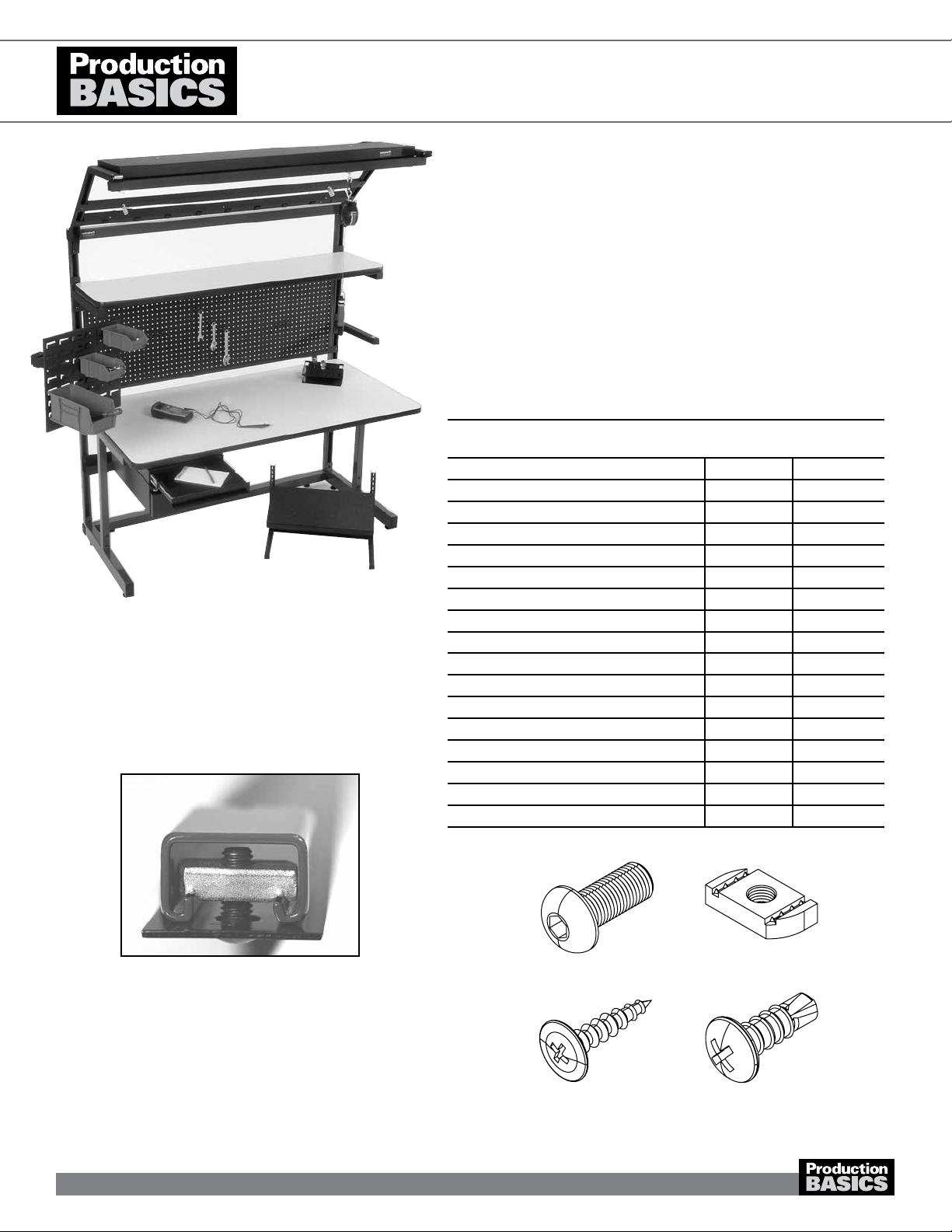
C-LEG STATIONS
Item Numbers 1000-1711
Workstations
Assembly Tips
• Review entire instruction manual before proceeding.
• Assembly How-to Videos available on-line
http://video.pbasics.com
• Production Basics name plate indicates front of frame.
• Basic Nut grooves must grip inside of frame channel for
support (see below).
• When initially securing Basic Bolts to Basic Nuts, attachment
is easy when nut and bolt are turned only one revolution.
• Legs are adjustable in 2-inch increments between 30-36
OR 36-42 inches high to customize worksurface height,
depending on products ordered.
• Don’t be a slave to gravity–recruit a co-worker to help you
install and correctly position components and accessories.
• References to ‘Left’ and ‘Right’ are oriented as if you were
facing the front of the workstation.
Basic Bolt Basic Nut
Wood Screw Tek Screw
C-Leg Stationwith optional accessories
1602A101
1

Production Basics, Inc. Massachusetts, USA 800.318.2770 617.926.8100 Fax: 617.926.8010 www.pbasics.com
ASSEMBLY VIDEOS AVAILABLE ON-LINE http://video.pbasics.com
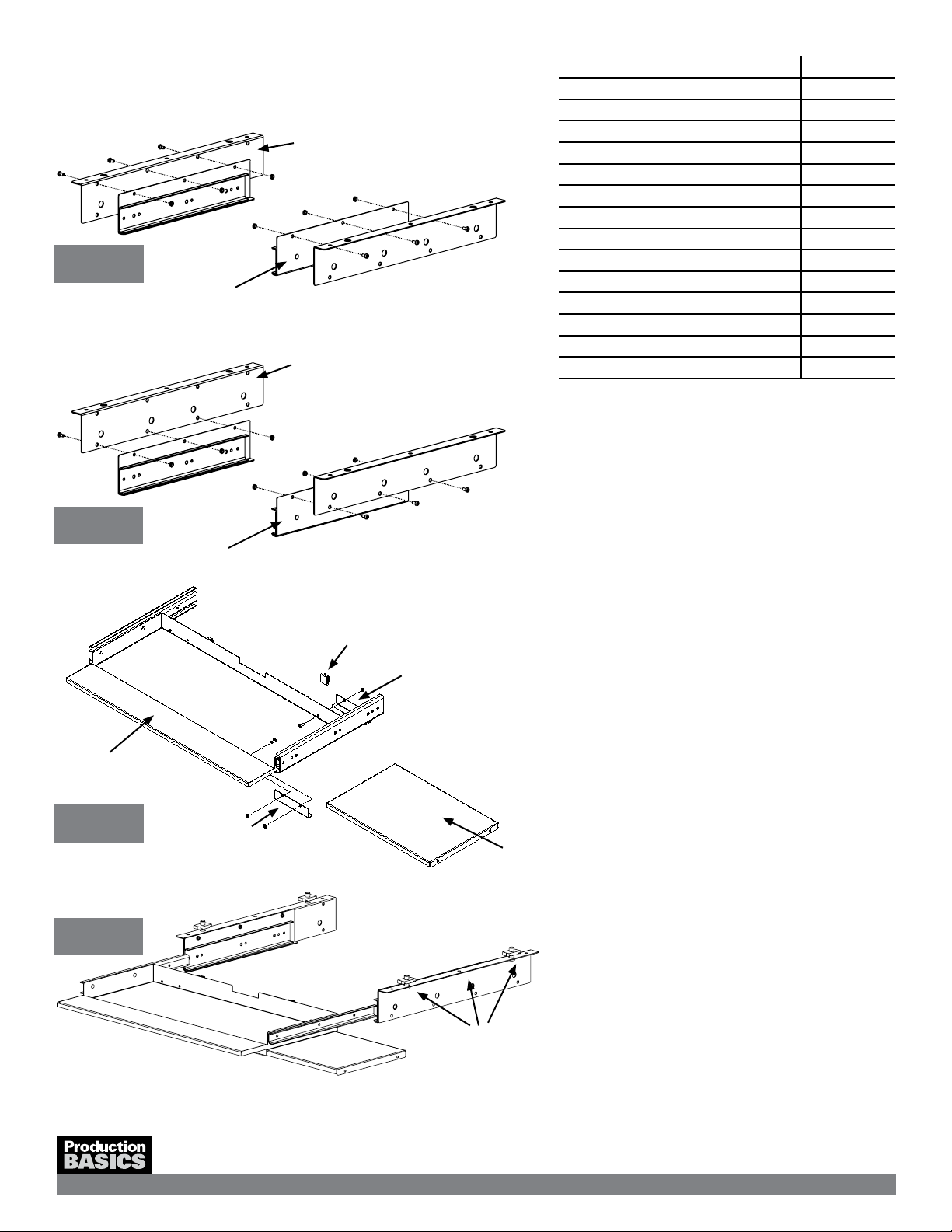
1. Insert two (2) Basic Bolts into pre-drilled holes
determining height. Repeat for other C-Leg.
2. Insert bolts into each hole at back of leg. Secure with
nut. Turn only one revolution. Repeat for other C-Leg.
3. Choose a leg for the right side of the station (as shown).
Attach Top Bracket to the inside of the C-Leg with tek
screws. This forms a shelf for the Worksurface Support
Rails. Repeat for other C-Leg.
4. Insert Basic Bolt from bottom into holes on Top
Bracket. Secure with nut. Turn only one revolution.
Repeat for left C-Leg with opposite bracket, for left
side of station.
a. If assembling Back-to-Back Stand Alone,
Back-to-Back multiple, or Side-by-Side Stations
prepare ALL C-Legs according to steps 1-4.
b. Quad and Side-by-Side Stations include one (1)
2C-Leg in place of two (2) C-Legs. Position the
2C-Leg in between adjacent stations (as shown).
5. Screw the Leveling Feet into bottom of C-Legs and
Frame. Use rubber mallet to tap End Caps into frame
and C-Legs.
a. For Side-by-Side & Quad Stations, end caps are not
used where frames meet.
b. If you have ordered casters, lock the caster and
turn the caster stem all the way into the leg until you
can no longer see the caster stem. Ensure caster is
completely tightened.
6. Lay Frame on a at, level surface, channel side up.
a. For Side-by-Side Stations, lay Frames next to each
other.
7. Insert Basic Nuts at back of leg into frame channel and
turn Basic Bolt 90 degrees clockwise to grip (see image
in Assembly Tips on page 1). Position C-Leg so that it
is parallel to vertical channel and ush with bottom of
frame. Tighten the bolts. Repeat with other C-Leg or
2C-Leg as applicable. Stand the station upright.
8. Place Worksurface Support Rails perpendicular to
Top Brackets, channel side down, on top of nuts (as
shown). Turn Basic Bolt 90 degrees clockwise to grip.
Tighten the bolts. Repeat for both sides of station and all
Worksurface Support Rails. 30”D C-Leg Stations have
two (2) Worksurface Support Rails; 36”D C-Leg Stations
have three (3).
9. Center the laminate worksurface on top of the
Worksurface Support Rails with T-mold seam at the
back. Ensure it is ush against the Frame. Attach the
worksurface from underneath with wood screws through
holes in Worksurface Support Rails
a. If assembling Back-to-Back Stations, repeat steps
7–9 for the other side of the configuration.
b. For different worksurfaces materials, an Assembly
Manual is included.
10. Check all attachments and give all the bolts a nal
tightening.
Worksurface Support Rail
2C Leg - Middle
Frame
C Leg - Right
Top Bracket
30”D Workstation
36”D Workstation
Steps 1-4
Step 4-7
Step 5a
Step 5b
Steps 8-9
see inset for detail
1602A101
2
Production Basics, Inc. Massachusetts, USA 800.318.2770 617.926.8100 Fax: 617.926.8010 www.pbasics.com
ASSEMBLY MANUAL
ASSEMBLY VIDEOS AVAILABLE ON-LINE http://video.pbasics.com
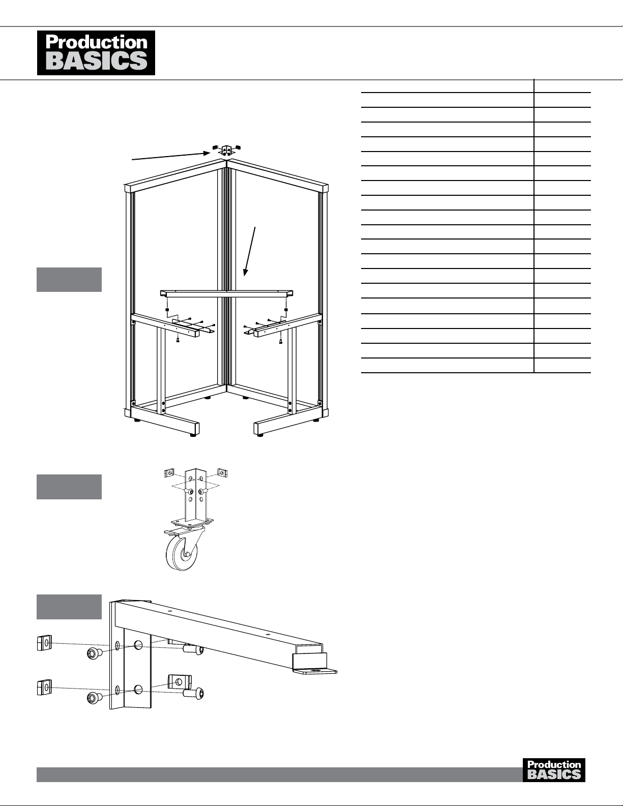
1. Prepare C-Legs as shown and described on page 2,
steps 1 through 6.
2. Lay frames on a at, level surface, channel side up.
3. Attach the C-Legs to the far left and far right of each
frame (as shown). Insert Basic Nuts at back of leg into
frame channel and turn Basic Bolt 90 degrees clockwise
to grip. Position C-Leg so that it is perpendicular to frame
and ush with bottom. Tighten the bolts. Repeat for other
C-Leg.
4. Stand the frames upright. Position frames at a
90-degree angle, with the channel facing forward. Place
Worksurface Support Rail, channel side down, on top of
Basic Nuts attached to Top Brackets, above the rearmost
hole position. Turn Basic Bolt 90 degrees clockwise to
grip but do not fully tighten. Repeat for other side.
5. Secure the frames by attaching the Frame Alignment
bracket using Basic Nuts & Bolts.
6. For corners workstations ordered with casters, use 2
Basic Bolts & Nuts to attach the 5th caster to the back
corner of the workstation where the 2 frames meet.
7. Insert a Basic Bolt into the four (4) mounting plate holes
on the Frame Joining Bracket. Secure with Basic Nut.
Turn only one revolution.
8. Attach Frame Joining Bracket, channel side down in the
corner between the Frames by inserting Basic Nuts into
frame channel. Turn Basic Bolt 90 degrees clockwise to
grip, but do not tighten.
PARTS AND HARDWARE QUANTITY
Frames 2
Height Adjustable C-Legs (2 pieces each) 2
Leveling Feet 8
Frame Joining Bracket 1
Worksurface Support Rail 1
Frame Alignment Bracket 1
Top Brackets 2
Laminate Worksurface 1
Basic Bolts 17
Basic Nuts 13
Wood screws 5
Tek screws 8
End Caps 12
7/32 Allen Wrench 1
Casters (if ordered) 5
Other Items Needed (not included)
Phillips head drill or screwdriver
Rubber Mallet
Level
Frame Joining Bracket
Worksurface Support Rail
STAND ALONE CORNER STATION
Item Numbers 1415, 1416, 1515, 1516, 1640-1648
Steps 3-5
Step 7
Step 6
Frame Alignment Bracket
1602A101
3
Need Help? Call Assembly Support at 800.318.2770
ASSEMBLY VIDEOS AVAILABLE ON-LINE http://video.pbasics.com
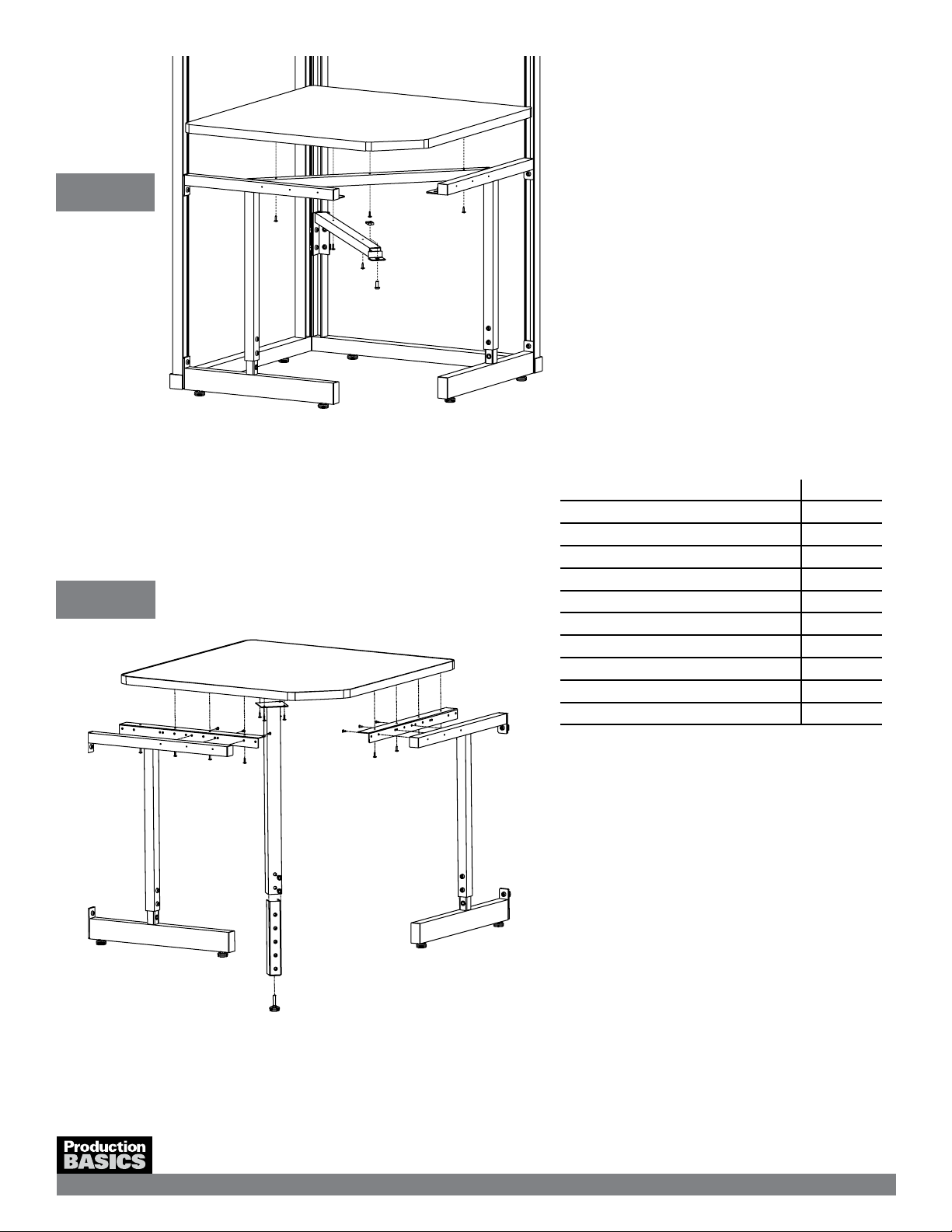
9. Insert a Basic Bolt from the bottom into the front tab of
the Frame Joining Bracket. Secure with Basic Nut. Insert
the nut into the worksurface Support Rail from below (as
shown) and turn Basic Bolt 90 degrees clockwise to grip.
10. Use a level to make sure the Worksurface Support Rail
and Frame Joining Bracket are positioned evenly. Bolts
may need to be slightly loosened for alignment and
re-tightened.
11. Place the laminate worksurface on top of the
Worksurface Support Rail and ensure it is ush against
the Frames and with the C-Legs on the sides. Attach the
worksurface from underneath with wood screws.
12. Check all attachments and give all nuts and bolts a nal
tightening.
1. Insert two (2) Basic Bolts into bottom of adjustable leg,
determining height. Screw in leveling foot.
2. Insert three (3) tek Screws through pre-drilled holes in
Top Bracket to outside of each existing C-Leg that joins
the corner. The bracket should be ush with the top of
the C-Leg.
3. Place the corner laminate worksurface in between the
workstations. Secure with wood screws through the Top
Bracket.
4. Use wood screws to attach adjustable leg to underside of
worksurface 1” from back edge.
• Note: Add-on Corner requires two (2)
Stand-Alone C-Leg Stations for proper
assembly. Assemble C-Leg Stations before
assembling Add-on Corner.
ADD-ON CORNER STATION
Item Numbers 1417-1419, 1517-1519
C-Leg from existing station
C-Leg from existing station
PARTS AND HARDWARE QUANTITY
Height-Adjustable Leg (2 pieces each) 1
Leveling Foot 1
Top Brackets 2
Laminate Worksurface 1
Basic Bolts 2
Wood screws 12
Tek screws 6
7/32 Allen Wrench 1
Other Items Needed (not included)
Phillips head drill or screwdriver
Step 8-12
Step 1-4
1602A101
4
ASSEMBLY MANUAL
Production Basics, Inc. Massachusetts, USA 800.318.2770 617.926.8100 Fax: 617.926.8010 www.pbasics.com
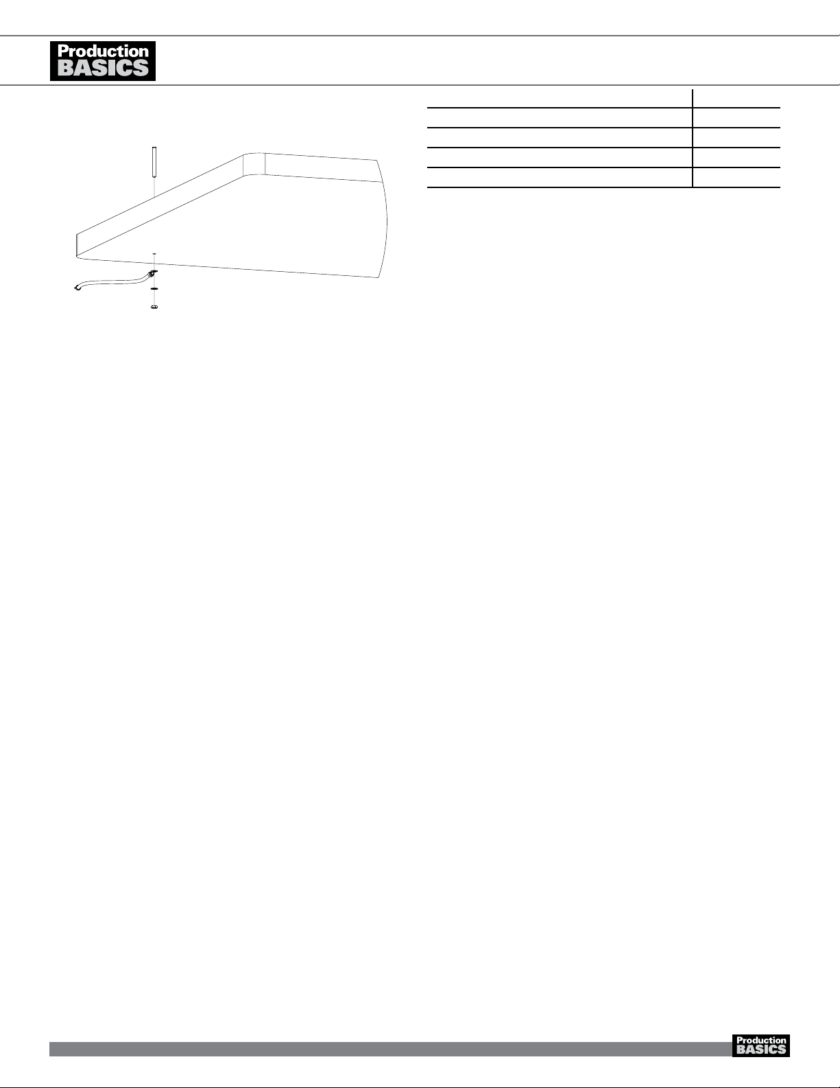
1. Insert Ground Bolt through top of worksurface through pre-drilled hole.
2. Slip ground wire over bolt underneath the worksurface. Add washer
and nut then tighten.
3. Ground other end of wire to electrical ground.
4. For additional information on grounding, contact your company’s ESD
manager or the ESD Association at 315.339.6937, www.esda.org.
GROUND BOLT
For ESD Laminate Worksurfaces and Shelving
PARTS AND HARDWARE QUANTITY
Ground Bolt 1
Ground Wire 1
Washer 1
Nut 1
ASSEMBLY VIDEOS AVAILABLE ON-LINE http://video.pbasics.com
1602A101
5
Production Basics, Inc. Massachusetts, USA 800.318.2770 617.926.8100 Fax: 617.926.8010 www.pbasics.com
ASSEMBLY MANUAL
ASSEMBLY VIDEOS AVAILABLE ON-LINE http://video.pbasics.com
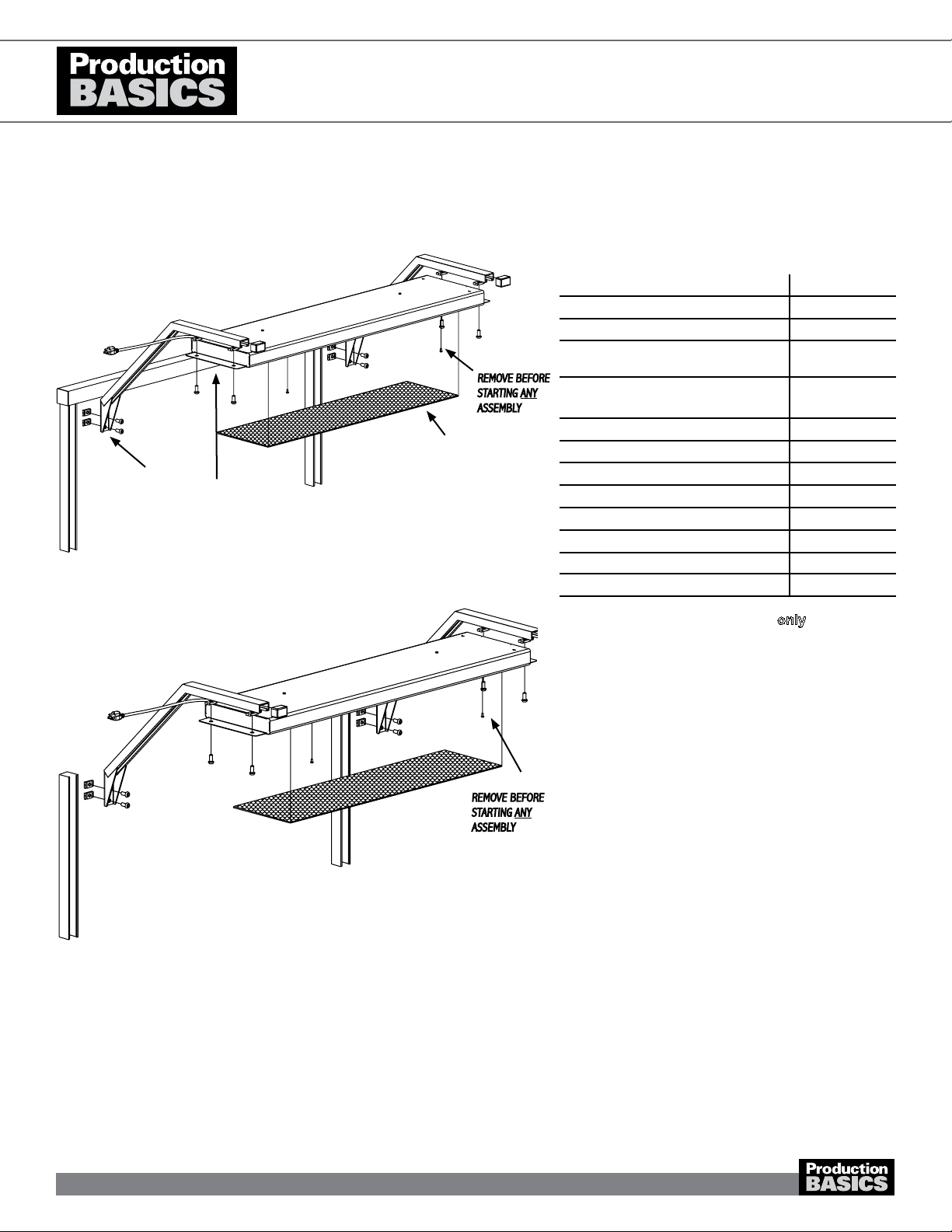
• Note: To install Overhead Arms only, perform
steps 3 & 4.
1. Unscrew 2 security screws on face of light unit.
Remove plastic diffuser.
2. Insert T8 light bulbs into xture. Plug light in to test
correct installation of bulbs. Replace diffuser and security
screws.
3. Insert two (2) Basic Bolts into mounting plate on
Overhead Arm. Secure with Basic Nut with grooves
facing the back of the mounting plate. Turn only one
revolution. Repeat for other Overhead Arm.
4. Insert Basic Nuts attached to Overhead Arm mounting
plate into frame channel of workstation or Uprights and
turn Basic Bolt 90 degrees clockwise to grip. Top of
mounting plate should be ush with top of frame cross
member. Tighten the bolts. Repeat for other Overhead
Arm.
5. Insert 4 Basic Bolts from bottom into light mounting plate.
Secure with 4 Basic Nuts with grooves facing down. Turn
only one revolution.
6. Position light unit with cord facing the frame. Insert Basic
Nuts attached to light unit into Overhead Arm channel
and turn Basic Bolt 90 degrees clockwise to grip.
7. Slide the light unit to the desired position. Tighten the
bolts. Slide End Caps onto front ends of Overhead Arms.
OVERHEAD LIGHT & OVERHEAD ARMS
Item Numbers 8500, 8504, 8505, 8510, 8512, 8514, 8516, 8518, 8538 ACCESSORIES
PARTS AND HARDWARE QUANTITY
Overhead Arms 2
End Caps 2
Basic Bolts 4 (Arms only)
8 (With light)
Basic Nuts 4 (Arms only)
8 (With light)
Light Unit 1
7/32 Allen Wrench 1
Other Items Needed (not included)
24” T8 bulb for 36” 3
36” T8 bulb for 48” 3
48” T8 bulb for 60” & 72” 3
Phillips head screwdriver
Tape Measure
Diffuser
Overhead Arm
mounting plate
Security Screws-
REMOVE BEFORE
STARTING ANY
ASSEMBLY
Light Mounting Plate
Overhead Light on Frame
Overhead Light on Uprights
Security Screws-
REMOVE BEFORE
STARTING ANY
ASSEMBLY
1602A101
6

Production Basics, Inc. Massachusetts, USA 800.318.2770 617.926.8100 Fax: 617.926.8010 www.pbasics.com
ASSEMBLY MANUAL
ASSEMBLY VIDEOS AVAILABLE ON-LINE http://video.pbasics.com
• Note: To install Overhead Arms only, perform
steps 3 & 4.
1. Install light mounting brackets on each end of light using
a 3-Lobe Knob and washers. Mounting bracket should be
ush with the top of the light unit.
a. To lock in the fixed position, install using 3-Lobe
Knob and sheet metal screws.
2. Insert Basic Bolts from bottom of each light mounting
bracket and secure with Basic Nuts. Turn only one
revolution. Repeat for other bracket.
3. Insert two (2) Basic Bolts into mounting plate on
Overhead Arm. Secure with Basic Nut with grooves
facing the back of the mounting plate. Turn only one
revolution. Repeat for other Overhead Arm.
4. Insert Basic Nuts attached to Overhead Arm mounting
plate into frame channel of workstation or Uprights and
turn Basic Bolt 90 degrees clockwise to grip. Top of
mounting plate should be ush with top of frame cross
member. Tighten the bolts. Repeat for other Overhead
Arm.
5. Position light unit with cord facing the frame. Insert Basic
Nuts attached to light unit into Overhead Arm channel
and turn Basic Bolt 90 degrees clockwise to grip.
6. Slide the light unit to the desired position. Tighten the
bolts. Slide End Caps onto front ends of Overhead Arms.
7. To adjust angle, loosen the 3-lobe knob on each end of
the light and tilt to desired angle. Tighten knobs.
OVERHEAD LIGHT, WITH DIMMER
Item Numbers 8900, 8901, 8902, 8903, 8904, 8905, 8906, 8907, 8908 ACCESSORIES
PARTS AND HARDWARE QUANTITY
Overhead Arms 2
End Caps 2
Basic Bolts 4 (Arms only)
8 (With light)
Basic Nuts 4 (Arms only)
8 (With light)
Light Unit 1
Light Mounting Brackets 2
7/32 Allen Wrench 1
3-Lobe Knob 2
1/4” Washer 2
Tek Screw 4
Other Items Needed (not included)
Phillips head screwdriver
Tape Measure
1602A101
7

Production Basics, Inc. Massachusetts, USA 800.318.2770 617.926.8100 Fax: 617.926.8010 www.pbasics.com
ASSEMBLY MANUAL
ASSEMBLY VIDEOS AVAILABLE ON-LINE http://video.pbasics.com
• Note: Install Overhead Arms (sold separately)
before Tool Trolley System.
1. Insert Basic Bolts into hole on Tool Track and secure
with Basic Nut.
2. Position Track spanning the width of the Overhead Arms.
Insert the Basic Nut into the Overhead Arm channel, turn
bolt 90 degrees and tighten.
3. Ensure an end cap is secure on each end of the Track
and there is a ‘brake’ positioned on each end of the
track.
TOOL TROLLEY SYSTEM
item Numbers 8339, 8340, 8343, 8346
PARTS AND HARDWARE QUANTITY
Tool Track 1
Trolley with clip 1
Trolley Brake 2
Basic Bolts 4
Basic Nuts 4
End Caps 2
7/32 Allen Wrench 1
Tool Trolley System on Frame
Tool Trolley System on Uprights
End Cap
Trolley with clip
Brake
Tool Track
1602A101
8

Production Basics, Inc. Massachusetts, USA 800.318.2770 617.926.8100 Fax: 617.926.8010 www.pbasics.com
ASSEMBLY MANUAL
ASSEMBLY VIDEOS AVAILABLE ON-LINE http://video.pbasics.com
• Note: Surface Mount method is not compatible
with C-Leg Series workstations.
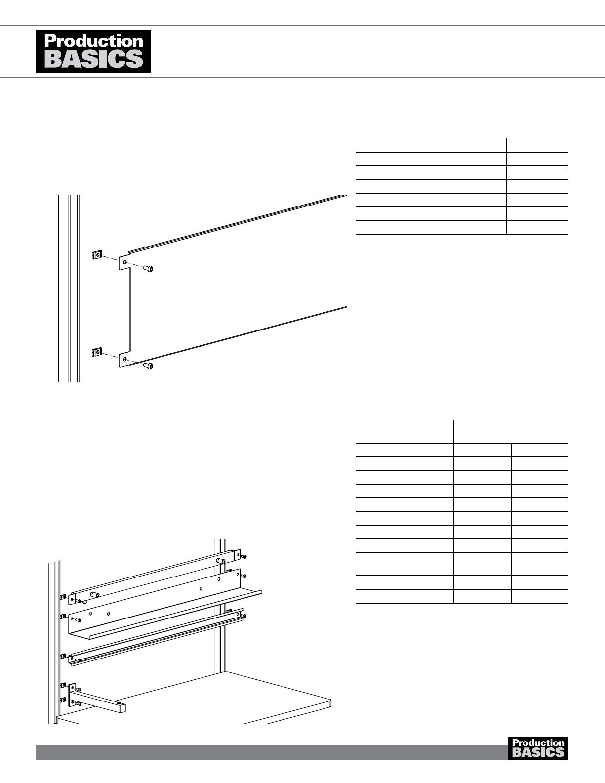
1. To install Power Rail to an Upright or Frame, attach
brackets to Power Rail as shown.
2. Insert a Basic Bolt into bracket. Add a Basic Nut and turn
one revolution.
3. Install Power Rail at any height on your Uprights, Frame
or Overhead Arms. Ensure the Power Rail is level before
tightening.
4. Alternate mounting to RTW, Easy-Lift or existing work
table with a 1.25” thick worksurface: use enclosed
bracket shown left to mount Power Rail to your
worksurface. Secure under the worksurface with wood
screws.
a. For other worksurface thicknesses, use bracket from
Step 1 and attach directly to surface.
POWER RAIL
Item Numbers 8319-8324, 8326, 8327
PARTS AND HARDWARE QUANTITY
Power Rail 1
Basic Bolt 2
Basic Nuts 2
Wood Screws 4
Bracket- frame mount 2
Bracket-table mount 2
Bracket bolts 4
7/32 Allen Wrench 1
Medium 1/8 Allen Wrench for bracket
bolts
1
Other Items Needed (not included)
Phillips head screwdriver or drill
Tape measure
Level
Bracket attachment for
surface mount Power Rail
Step 1
Step 4
Step 4a
Steps 2-3
1602A101
9
Production Basics, Inc. Massachusetts, USA 800.318.2770 617.926.8100 Fax: 617.926.8010 www.pbasics.com
ASSEMBLY MANUAL
ASSEMBLY VIDEOS AVAILABLE ON-LINE http://video.pbasics.com
1. Insert a Basic Bolt into the holes on the product’s
mounting plate. Secure with a Basic Bolt by turning one
revolution.
2. Insert the nuts into the Frame or Uprights and tighten
bolts.
3. Repeat for other side
1. Insert a Basic Bolt into the holes on the product’s
mounting plate. Secure with a Basic Nut by turning one
revolution.
2. Insert the nuts into the Frame or Uprights and tighten
bolts.
3. Repeat for other side.
GLOBAL INSTALLATION: These instructions apply to the following accessories:
Peg Board Item Numbers 8721-8724
Bin Panel Enclosure Item Numbers 8312-8315
Tack Board Item Numbers 8729, 8730, 8733, 8735
Modesty Panel Item Numbers 8705, 8709, 8712, 8715
Magnetic Dry Erase Board Item Numbers 8716-8719
Multi- Panel Enclosures Item Numbers 8776-8797
GLOBAL INSTALLATION: These instructions apply to the following accessories:
Tool Shelf and Bin Rail Item Numbers 8492-8494
Universal Mount Item Numbers 8640, 8643
Cable Trough Item Numbers 8620-8623
Binder Holder Item Numbers 8352
Document Holder Item Numbers 8353
Peg Board Panel Item Numbers 8626, 8649
Parts Bin Panel Item Numbers 8627, 8639
Tray Arm Item Numbers 8630, 8631
Flat Screen Monitor Arm Item Numbers 8632
Air Rail Item Numbers 8330, 8331, 8333, 8336
Bin Rail Item Numbers 8300, 8301, 8303, 8306
Universal Mounting Bar Item Numbers 8675-8678
ACCESSORIES
PARTS AND HARDWARE QUANTITY
Basic Bolts 4
Basic Nuts 4
7/32 Allen Wrench 1
Other Items Needed (not included)
Tape Measure
Level
PARTS AND
HARDWARE
QUANTITY
BASIC BOLTS BASIC NUTS
Tool Shelf and Bin Rail 2 2
Universal Mount 2 2
Cable Trough 2 2
Binder Holder 2 2
Parts Bin Panel 2 2
Air Rail 2 2
Bin Rail 2 2
7/32 Allen Wrench 1
Other Items Needed
(not included)
Tape Measure
Level
1602A101
10

Need Help? Call Assembly Support at 800.318.2770
1. Attach extension to back of Parts Bin Rail by inserting a
Basic Bolt through hole on the Bin Rail and into Extension.
Repeat for other side. Tighten bolts.
2. Insert Basic Bolt through mounting plate on Extension,
secure with a Basic Nut, turning one revolution.
3. Insert the nuts into the Frame or Uprights and tighten
bolts.
1. Insert Basic Bolt into holes on bracket. Secure with a Basic
Nut turning one revolution.
2. Insert Nuts into Frame or Upright and tighten bolts. Notches
on brackets face inward, as shown. Repeat for other
bracket. Measure or use a level to ensure brackets are at
the same height.
3. Insert the bar clip into one of 3 positions on the bracket.
Repeat for other bar clip in the same position.
4. Add labels, foam or paper rolls to rod and nest rod into
each bar clip.
BIN RAIL EXTENSION
Item Numbers 8308, 8310
ENCLOSURES: PAPER & LABEL ROLL HOLDER
Item Numbers 8740-8743
Bin Rail Extension
Bar Clip
PARTS AND HARDWARE QUANTITY
Basic Bolts 2
Basic Nuts 2
Bin Rail Extension 2
7/32 Allen Wrench 1
PARTS AND HARDWARE QUANTITY
Paper Roll Bar 1
Brackets 2
Bar Clip 2
Basic Bolts 4
Basic Nuts 4
7/32 Allen Wrench 1
Paper Roll Bar
Brackets
1. Insert Basic Bolt into holes on bracket. Secure with a Basic
Nut turning one revolution.
2. Position brackets on the left and right with bracket ange on
the inside, as shown. Insert Nuts through bracket and into
Frame or Upright as shown in diagram and tighten bolts.
Repeat for other bracket. Measure or use a level to ensure
brackets are at the same height.
3. Position rail supports as shown. Line up holes on rail
supports with holes on bracket ange. Insert a handle into
the hole from the inside (recommended) and secure with a
kep nut.
4. To install slide rails, position rails to accommodate your
circuit boards and insert a threaded stud through the bottom
of the rail support and slide rail. Secure with silver knob.
ENCLOSURES: SLIDE LINE
Item Numbers 8770- 8773
Rail Support
Slide Rails
Threaded Stud
Bracket
PARTS AND HARDWARE QUANTITY
Slide Rails 2
Brackets 2
Rail Support 2
Basic Bolts 4
Basic Nuts 4
Handles 2
Kep Nut 2
Threaded Stud and Knob 4
7/32 Allen Wrench 1
ASSEMBLY VIDEOS AVAILABLE ON-LINE http://video.pbasics.com
1602A101
11
Production Basics, Inc. Massachusetts, USA 800.318.2770 617.926.8100 Fax: 617.926.8010 www.pbasics.com
ASSEMBLY MANUAL
ASSEMBLY VIDEOS AVAILABLE ON-LINE http://video.pbasics.com
1. Insert Basic Bolt into holes on bracket. Secure with a
Basic Nut turning one revolution.
2. Insert Nuts into Frame or Upright and tighten bolts.
Notches on brackets face inward. Repeat for other
bracket. Measure or use a level to ensure brackets are
at the same height.
3. Insert the shelf cross bar into frontmost position
(recommended).
4. Place shelf on top of bracket installation and secure with
wood screws underneath the shelf.
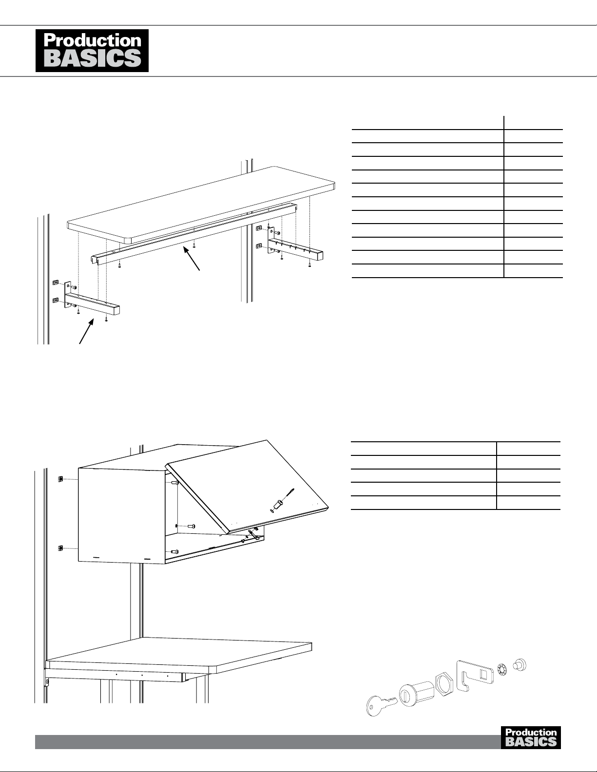
SHELVING: LAMINATE SHELF
Item Numbers 8417-8439, 8449-8461
ACCESSORIES
PARTS AND HARDWARE QUANTITY
Laminate Shelf 1
Brackets 2
Cross Bar 1
Basic Bolts 4
Basic Nuts 4
Wood Screws 8
7/32 Allen Wrench 1
Other Items Needed (not included)
Phillips head screwdriver or drill
Tape Measure
Level
Bracket
Shelf Cross Bar
1. Open Storage Cabinet and slide door back.
2. Insert Basic Bolts into the holes on the inside corners
of the Cabinet. Secure with a Basic Nuts and turn one
revolution.
3. Position Storage Cabinet on frame and turn bolts 90
clockwise to grip channel. Tighten bolts.
4. To install the lock, push the lock mechanism through the
hole in front of the cabinet door. Assemble as shown.
Ensure the unthreaded part of the lock and the key teeth
face upwards.
PARTS AND HARDWARE QUANTITY
Storage Cabinet 1
Lock mechanism 1
Basic Bolts 4
Basic Nuts 4
7/32 Allen Wrench 1
STORAGE CABINET
Item Numbers 8551-8553
Lock Detail
1602A101
12

Need Help? Call Assembly Support at 800.318.2770
ASSEMBLY VIDEOS AVAILABLE ON-LINE http://video.pbasics.com
1. Insert Basic Bolts into holes on all three brackets.
Secure with a Basic Nut turning one revolution.
2. On the left side of the Corner Station, install bracket on
Frame or Upright and tighten bolts. Notches on bracket
face inward. Repeat for other bracket. Measure or use a
level to ensure brackets are at the same height.
3. Insert the shelf cross bar into frontmost position on the
brackets (recommended).
4. On the right side of the Corner Station, install the third
bracket. Measure or use a level to ensure all three
brackets are at the same height.
5. Place shelf on top of bracket installation and secure with
wood screws through the brackets and into the shelf.
SHELVING: LAMINATE CORNER
Item Numbers 8485, 8486, 8488, 8489
Left Right
PARTS AND HARDWARE QUANTITY
Laminate Shelf 1
Brackets 3
Shelf Cross Bar 1
Basic Bolts 6
Basic Nuts 6
Wood Screws 10
7/32 Allen Wrench 1
Other Items Needed (not included)
Phillips head screwdriver or drill
Tape Measure
Level
1. Assemble bracket as shown.
2. Invert bracket and place on underside of shelf.
3. Align laminate ush with the bracket ange and sides.
4. Attach shelf with wood screws through the bracket and
into the shelf.
5. Insert a Basic Bolt into each hole at back of shelf
bracket, top and bottom. Secure with Basic Nut. Turn
only one revolution.
6. Turn shelf over and insert nuts into frame underneath the
worksurface.
SHELVING: LAMINATE UNDER-SURFACE
Item Numbers 8440-8448
Shelf Underside
PARTS AND HARDWARE QUANTITY
Laminate Shelf 1
Brackets 2
Shelf Cross Bar 1
Basic Bolts 4
Basic Nuts 4
Wood Screws 8
7/32 Allen Wrench 1
Other Items Needed (not included)
Phillips head screwdriver or drill
Tape Measure
Level
1602A101
13

Production Basics, Inc. Massachusetts, USA 800.318.2770 617.926.8100 Fax: 617.926.8010 www.pbasics.com
ASSEMBLY MANUAL
ASSEMBLY VIDEOS AVAILABLE ON-LINE http://video.pbasics.com
1. Insert Basic Bolt into holes on shelf bracket. Secure with
Basic Nut and turn only one revolution. Repeat for other
side of bracket.
2. Position brackets as shown. Insert Basic Nuts attached
to shelf bracket tabs into frame channel. Turn Basic Bolt
90 degrees clockwise to grip.
3. Slide brackets to desired height. Measure or use a level
to ensure brackets are at the same height. Tighten
brackets on frame or uprights.
4. Position shelf to line up with adjustment slots on bracket.
Insert handle from outside into adjustment slots and
secure with kep nut. Repeat for all four handles.
1. Insert Basic Bolt into holes on shelf bracket. Secure with
Basic Nut and turn only one revolution. Repeat for other
bracket.
2. Position brackets as shown. Insert Basic Nuts attached
to shelf bracket tabs into frame channel. Notches
indicate top of bracket. Turn Basic Bolt 90 degrees
clockwise to grip. Measure or use a level to ensure
brackets are at the same height.
3. Attach the shelf to the bracket. Nest shelf in notches and
pull forward to lock in place. Tighten brackets on frame
or uprights.
ACCESSORIES
PARTS AND HARDWARE QUANTITY
Metal Universal Shelf 1
Brackets 2
Basic Bolts 4
Basic Nuts 4
Handles 4
Kep Nuts 4
7/32 Allen Wrench 1
Other Items Needed (not included)
Phillips head screwdriver or drill
Tape Measure
Level
Universal Shelf- inverted with a 1” lip.
Adjustment Slot
SHELVING: WIRE
Item Numbers 8400, 8401, 8403, 8406
PARTS AND HARDWARE QUANTITY
Wire Shelf 1
Brackets 2
Basic Bolts 4
Basic Nuts 4
7/32 Allen Wrench 1
Other Items Needed (not included)
Tape Measure
Level
• Note: Universal Shelf can be installed as at
surface or sloped with a 1-inch lip.
SHELVING: UNIVERSAL
Item Numbers 8390-8397, 8410-8416
Bracket
Basic Nut
Basic Bolt
Kep Nuts
Basic Nut
Basic Bolt
1602A101
14
Production Basics, Inc. Massachusetts, USA 800.318.2770 617.926.8100 Fax: 617.926.8010 www.pbasics.com
ASSEMBLY VIDEOS AVAILABLE ON-LINE http://video.pbasics.com
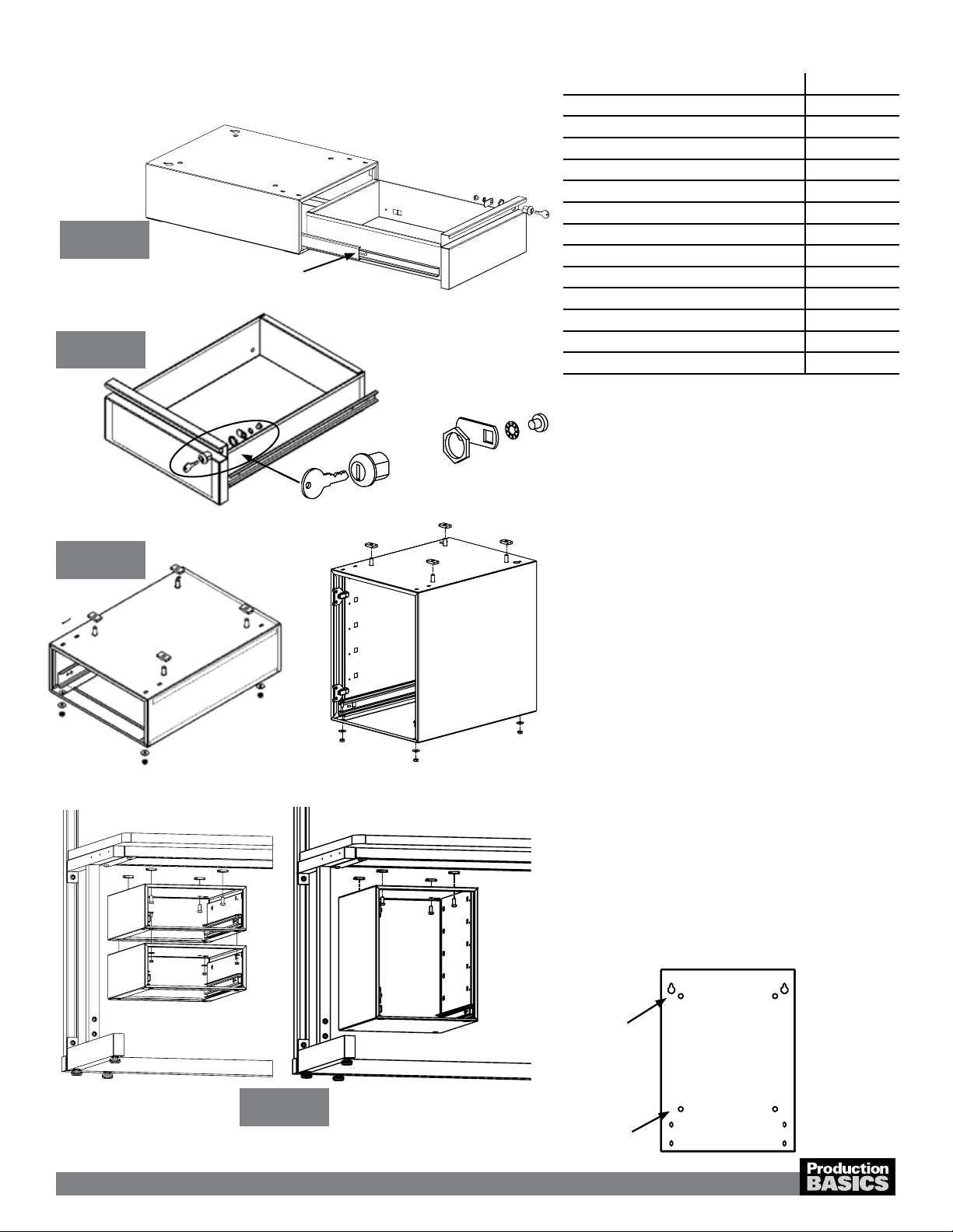
1. If installing cabinet, start with Step 2. Remove the drawer
from the chassis by extending drawer and pushing
down/up on the black tabs on both sides of the drawer
and pull the drawer forward.
2. If not using locks, skip to Step 3. Using the allen wrench,
punch out the lock knock-out on the front side of the
drawer or cabinet. Assemble lock mechanism as shown.
Ensure the unthreaded part of the lock and key teeth
face upward.
3. Insert a Basic Bolt from the inside of the drawer or
cabinet chassis and secure with Basic Nut, turning one
revolution. Repeat for all four corners.
4. Insert attached Basic Nuts into Worksurface Support
Rail channel and turn Basic Bolt 90 degrees clockwise to
grip. Position chassis under worksurface as desired and
tighten bolts.
a. If stacking items, insert small bolt from above into
the pre-drilled hole in bottom back of chassis and
lightly secure with nut and washer.
b. Align second chassis’ back keyhole slot with nuts
and pull forward. This will help you support the
drawer while securing other nuts and bolts for
stacking drawers.
c. Give all nuts and bolts a final tightening.
5. Push in drawer slides on chassis and insert complete
drawer into chassis.
DRAWERS & SUSPENDED CABINET:
C-LEG AND EASY-LIFT, DUAL LEG UNITS
Item Numbers 8600, 8605, 8607, 8610, 8613, 8615, 8617
PARTS AND HARDWARE QUANTITY
Drawer 1
Drawer or Cabinet Chassis 1
Lock Mechanism (if ordered) 1
Keys 2
Basic Bolts 4
Basic Nuts 4
Bolts (used for stacking drawers) 4
Kep Nuts (used for stacking drawers) 4
Washers (used for stacking drawers) 4
7/32 Allen Wrench 1
Other Items Needed (not included)
Phillips head screwdriver
Open end wrench
Keyhole details for
stacking drawers
Use hole set for hanging
first drawer -step 3
1. If installing cabinet, start with Step 2. Remove the drawer
from the chassis by extending drawer and pushing
down/up on the black tabs on both sides of the drawer
and pull the drawer forward.
2. If not using locks, skip to Step 3. Using the allen wrench,
punch out the lock knock-out on the front side of the
drawer or cabinet. Assemble lock mechanism as shown.
Ensure the unthreaded part of the lock and key teeth
face upward.
3. Insert a Basic Bolt from the inside of the drawer or
cabinet chassis and secure with Basic Nut, turning one
revolution. Repeat for all four corners.
4. Insert attached Basic Nuts into Worksurface Support
Rail channel and turn Basic Bolt 90 degrees clockwise to
grip. Position chassis under worksurface as desired and
tighten bolts.
a. If stacking items, insert small bolt from above into
the pre-drilled hole in bottom back of chassis and
lightly secure with nut and washer.
b. Align second chassis’ back keyhole slot with nuts
and pull forward. This will help you support the
drawer while securing other nuts and bolts for
stacking drawers.
c. Give all nuts and bolts a final tightening.
5. Push in drawer slides on chassis and insert complete
drawer into chassis.
DRAWERS & SUSPENDED CABINET:
C-LEG AND EASY-LIFT, DUAL LEG UNITS
Item Numbers 8600, 8605, 8607, 8610, 8613, 8615, 8617
Black tabs- push up/down to release drawer
Keyhole details for
stacking drawers
Use hole set for hanging
first drawer -step 3
Step 1
Step 2
Step 3
Steps 4-5
• Note: Drawer locks are sold separately.
1602A101
15

Production Basics, Inc. Massachusetts, USA 800.318.2770 617.926.8100 Fax: 617.926.8010 www.pbasics.com
ASSEMBLY MANUAL
ASSEMBLY VIDEOS AVAILABLE ON-LINE http://video.pbasics.com
1. Attach Keyboard Tray Base to Tray Extender with two (2)
8-32 bolts and nuts.
2. Attach Mouse Pad to Keyboard Tray Base using four (4)
8-32 bolts and nuts. Mouse Pad can be positioned on
right, left or center front of Tray Base. Use adjustment
slots for proper sizing.
3. Install full assembly to the back of your Flat Screen
Monitor Arm (sold seperately), through the mounting plate
and then through the monitor. The Flat Screen Monitor
Arm mounting plate should be sandwiched between the
Add-on Keyboard Tray assembly and your monitor. Use
the bolts that came with your Flat Screen Monitor Arm.
FLAT SCREEN MONITOR ARM AND
ADD-ON KEYBOARD TRAY
Item Numbers 8632, 8634 + 8633 PARTS AND HARDWARE QUANTITY
Keyboard Tray Base 1
Tray Extender 1
Mouse Pad 1
8-32 bolts 6
8-32 nuts 6
M4 x 14mm 4
Allen Wrench 1
Other Items Needed (not included)
Flat Screen Monitor Arm
ACCESSORIES
• Note: Monitor Arm and Add-on Keyboard Tray
sold separately.
Step 3
Step 2
Step 1
1602A101
16

Production Basics, Inc. Massachusetts, USA 800.318.2770 617.926.8100 Fax: 617.926.8010 www.pbasics.com
ASSEMBLY MANUAL
ASSEMBLY VIDEOS AVAILABLE ON-LINE http://video.pbasics.com
1. Before assembling the keyboard support with the
enclosed instructions, attach mounting plate to adapter
using button head bolts and nuts provided. See diagram
at left.
2. Insert a Basic Bolt into the corner holes of the adapter
and secure with a Basic Nut, turning only one revolution.
See diagram at left. For RTW Tables, proceed to step
4a.
3. Insert nuts attached to adapter into Worksurface Support
Rails on your workstation, as shown. Turn Basic Bolt 90
degrees clockwise to grip. Tighten the bolts.
4. Proceed with enclosed instructions for your keyboard.
a. For RTW Tables, insert wood screws through holes
on tabs to attach Keyboard Support to underside of
worksurface.
5. Secure the wrist support by inserting plastic screws from
the bottom and tighten.
ADJUSTABLE KEYBOARD SUPPORT
Item Numbers 8680 PARTS AND HARDWARE QUANTITY
Adapter Plate 1
Mounting Plate 1
8/32 Button head bolt 6
Nuts 6
Washers 6
Wood screws 4
Basic Bolts 4
Basic Nuts 4
7/32 Allen Wrench 1
3/32 Allen Wrench 1
See Step 1
Adapter Plate
See Step 4a for RTW Tables,
Easy-Lift 4-Post
See Step 2 for C-Leg,
Easy-Lift Dual-Leg
Mounting Plate
Adapter Plate
1602A101
17
Need Help? Call Assembly Support at 800.318.2770
1. Using three (3) 8-32 x 3/8” nuts and bolts, assemble
Upper and Lower Side Brackets as shown for right and left
brackets, according to your style of workstation.Set aside
until step 4.
a. For C-Leg & Easy-Lift Dual-Leg workstations,
assemble brackets so that the Upper and Lower Side
Brackets are flush against each other.
b. For RTW, Easy-Lift 4-Post or PedSys workstations,
assemble brackets so that the Lower Side Brackets
extend below the Upper Side Brackets.
2. Choose right or left side for mouse tray. Using two (2) 8-32
x 3/8” bolts, hex nuts and washers, install the mouse pad
bracket onto the keyboard tray under the back lip of the
wrist rest. Slide the tray onto the bracket and repeat for the
rear mouse pad bracket with tray in place. The mouse tray
should slide freely. A lip on the tray acts as a stop.
3. Attach adhesive backed cable clip to back of keyboard tray.
These hold your mouse and keyboard wires in place.
4. Slide keyboard onto left and right side brackets as shown.
5. For C-Leg and Easy-Lift workstations insert a Basic Bolt
through the two (2) large holes on top of each bracket from
step 1. Secure with a Basic Nut. Turn one revolution.
a. For RTW, use wood screws to attach to underside of
worksurface. Go to Step 6.
6. Position the keyboard under the workstation. Insert the
Basic Nuts attached to the bracket into the Worksurface
Support Rail and tighten the bolts.
PARTS AND HARDWARE QUANTITY
Upper Side Bracket 2
Lower Side Bracket 2
Basic Bolts 4
Basic Nuts 4
Keyboard Drawer 1
Cable Clip 2
Mouse Pad Bracket 2
Mouse Tray 1
8-32 Bolts 10
8-32 Nuts 10
Wood Screws 6
3/32 Allen Wrench 1
Other Items Needed (not included)
Phillips head drill
KEYBOARD DRAWER
item Number 8681
Upper side Bracket- C-leg/Easy-Lift Dual Leg, left side
Lower Side Bracket C-Leg/EasyLift Dual Leg, right side
Upper side Bracket- RTW/Easy-Lift 4-Post, left side
Lower Side Bracket RTW/Easy-Lift 4-Post, PedSys, left side
Cable Clip
Mouse Tray
Completed Keyboard Drawer for
C-Leg/Easy Lift Dual Leg
See Step 4a for RTW Table,
Easy-Lift 4-post, PedSys
Wrist Rest
Rear Mouse Pad Bracket
Mouse Pad Bracket
Step 1a
Step 1b
Steps 2-3
Steps 4-6
ASSEMBLY VIDEOS AVAILABLE ON-LINE http://video.pbasics.com
1602A101
18
Production Basics, Inc. Massachusetts, USA 800.318.2770 617.926.8100 Fax: 617.926.8010 www.pbasics.com
ASSEMBLY MANUAL
ASSEMBLY VIDEOS AVAILABLE ON-LINE http://video.pbasics.com
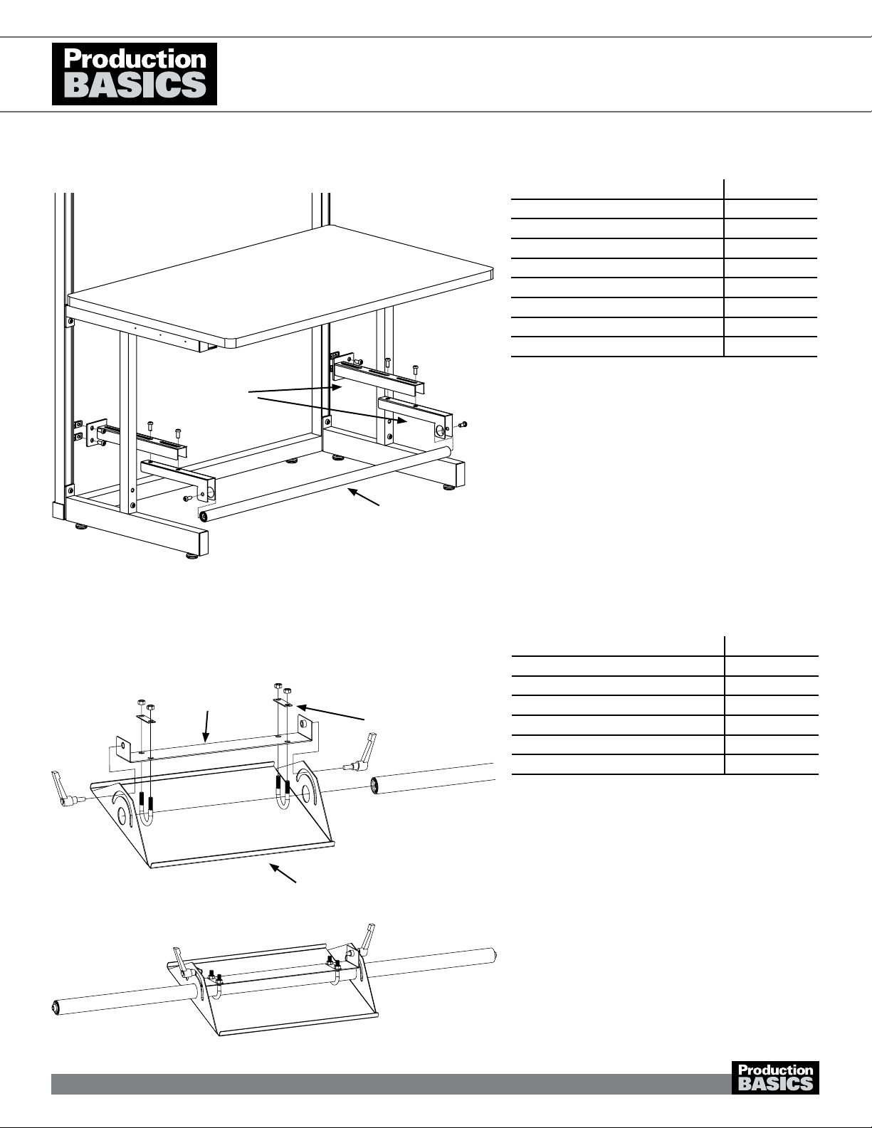
1. Assemble Footrest Plate Bracket as shown.
2. Slip Footrest Tube through holes in Footrest Plate and
the U-Bolts.
3. Secure by inserting the handle into the nut on the Plate
Support.
4. To adjust Footrest Plate placement, loosen or tighten
U-Bolt on underside of plate. To adjust angle, use
handles on the side.
5. Attach footrest as directed above.
• Note: Footrest Plate must be installed on Tube
Footrest before tube is secured into position.
FOOTREST PLATE
Item Number 8668 PARTS AND HARDWARE QUANTITY
Footrest Plate 1
Plate Support 1
U-Bolts 2
Nuts 4
Handles 2
U-Bolt Retainer Plate 2
Plate Support
Footrest Plate
U-Bolt Retainer Plate
1. Prepare brackets as shown. Brackets are LEFT and
RIGHT specic. Adjust bracket according to operator
comfort and depth of workstation.
2. Attach footrest tube between the bracket assemblies
using a Basic Bolt.
3. Insert a Basic Bolt into the mounting plate on the bracket
assembly and secure with a Basic Nut turning one
revolution. Repeat for other bracket.
4. Install bracket onto frame under the worksurface.
Measure or use a level to ensure brackets are at the
same height. Repeat for other bracket.
• Note: Adjust bracket position to accommodate
operator and depth of station.
ACCESSORIES
C-LEG ADJUSTABLE TUBE FOOTREST
Item Numbers 8664, 8665, 8666, 8667
Bracket
Footrest Tube
Left
PARTS AND HARDWARE QUANTITY
Footrest Tube 1
Brackets (2 pieces each) 2
Basic Bolts 10
Basic Nuts 4
7/32 Allen Wrench 1
Other Items Needed (not included)
Tape Measure
Level
1602A101
19
Table of contents
Other Production Basics Desktop manuals


