Prodys ProntoNet LC User manual


ProntoNetLC User Manual
2
Index
Index ............................................................................... 2
CE Declaration of Compliance.................................................. 7
Introduction....................................................................... 8
Installation Guide ...............................................................10
II.1 Initial checks .......................................................................10
II.2 Installation .........................................................................10
II.3 The rear panel .....................................................................10
II.3.1 Power ...........................................................................11
II.3.2 Ethernet port – the LAN Connector.........................................11
II.3.2.1. ISDN Port Optional).......................................................12
II.3.2.2. X21 Port .....................................................................13
II.3.3 RS 232 Ports....................................................................14
II.3.4 GPIO Port.......................................................................15
II.3.4.1. Inputs........................................................................16
II.3.4.2. Outputs......................................................................16
II.3.5 Audio interfaces...............................................................16
II.3.5.1. Analog audio I/O ...........................................................16
II.3.5.2. AES/EBU Interface.........................................................16
II.3.6 Microswitches..................................................................17
The Front anel .................................................................18
III.1 DISPLAY.............................................................................18
III.1.1 STATUS SCREEN ...............................................................18
III.2 Control Keys .......................................................................22
III.2.1 The CALL 1 and CALL 2 keys ................................................22
III.2.1.1. Establishing a call when ProntoNetLC is configured as an IP codec
..........................................................................................23
III.2.1.2. Establishing a call when ProntoNetLC is configured as an IP Multi-
Unicast codec NET = IP) ............................................................24
III.2.1.3. Establishing a call when ProntoNetLC is configured as an X21 codec
..........................................................................................24
NET = X21)............................................................................24
III.2.2 The INF key....................................................................25
III.2.2.1. Screen 1: Audio input VU meters .......................................25
III.2.2.2. Screen 2: Audio output VU meters ..................................... 25
III.2.2.3. Screen 3: Decoding algorithm ...........................................26
III.2.2.4. Screen 4: Encoding algorithm ........................................... 26
III.2.2.5. Screen 5: LAN port configuration parameters .......................27
III.2.2.6. Screen 6: General configuration ........................................27

ProntoNetLC User Manual
3
III.2.2.7. Screen 7: GPIO and Serial Port bit rate................................27
III.2.3 The BOOK Key.................................................................28
THE MENU ........................................................................29
IV.1 The Controls: Navigation keys ..................................................29
IV.2 Main Menu .........................................................................29
IV.3 NET: Selecting a communications port. ....................................... 30
IV.4 ENC: Encoder algorithm selection menu ...................................... 30
IV.4.1 Configuration of Encoder 1 .................................................31
IV.4.2 PCM.............................................................................32
IV.4.3 G711............................................................................32
IV.4.4 G722:........................................................................... 32
IV.4.5 MPEG Layer II .................................................................33
IV.4.6 MPEG Layer III.................................................................34
IV.4.7 AAC 2,4 LC.....................................................................35
IV.4.8 AAC LD .........................................................................36
IV.4.9 AAC HE .........................................................................37
IV.4.10 apX ............................................................................38
IV.4.11 STD APTX .....................................................................38
IV.4.12 ENH APTX ....................................................................39
IV.5 Configuration of Encoder 2......................................................41
IV.6 CONF: General configuration Menu ............................................42
IV.6.1 CONF – AUD....................................................................42
IV.6.1.1. AUDIO IN....................................................................42
IV.6.1.2. AUDIO LEVELS .............................................................43
IV.6.2 CONF-PORTS ..................................................................43
IV.6.2.1. LAN..........................................................................44
IV.6.2.2. ISDN .........................................................................46
For Line 2 the options are laid out in the same way. ...........................48
IV.6.2.3. Configuration of the X21 port ...........................................48
IV.6.2.4. Configuration of the RS232 ports .......................................48
IV.6.3 CONF-SYS ......................................................................49
IV.6.3.1. Loop.........................................................................49
IV.6.3.2. PLL ..........................................................................50
IV.6.3.3. FAN..........................................................................50
IV.6.3.4. AUXDATA ...................................................................50
IV.6.3.5. KEYPAD .....................................................................51
IV.6.3.6. IPCODEC ....................................................................52
IV.6.3.7. BUZZER .....................................................................52
IV.6.3.8. RESET .......................................................................52
IV.6.4 CONF-BOOK....................................................................53
IV.7 INF ..................................................................................54
IV.7.1 Versions........................................................................54
IV.7.2 AUX DATA...................................................................... 54

ProntoNetLC User Manual
4
Remote Control .................................................................55
V.1 General Configuration ............................................................62
V.1.1 Interfaces ...................................................................... 63
V.1.1.1. LAN port.....................................................................63
V.1.1.2. ISDN Terminal adaptor Configuration...................................68
V.1.1.3. X21 Port .....................................................................70
V.1.1.4. RS232 Ports .................................................................70
V.1.1.5. GPIO Port ...................................................................71
V.1.2 Audio Configuration...........................................................74
V.1.3 System Configuration.........................................................75
V.1.3.1. TimeDate ...................................................................77
V.1.3.2. Password ....................................................................78
V.1.3.3. Aux Data ....................................................................78
V.1.3.4. Software Versions..........................................................79
V.1.3.5. Alarms .......................................................................80
V.1.3.6. Backup.......................................................................80
V.1.3.7. Scheduler ...................................................................80
V.1.3.8. Advanced....................................................................81
V.1.3.9. Exporting / Importing the configuration ...............................81
V.1.4 Streaming ...................................................................... 81
V.1.4.1. Protocol .....................................................................82
V.1.4.2. Tx ............................................................................83
V.1.4.3. Rx ............................................................................85
V.1.4.4. Test ..........................................................................86
V.1.4.5. Real Time Monitoring .....................................................88
V.1.5 Phone Book.....................................................................90
V.2 Call Log .............................................................................91
V.3 Controlling the ProntoNetLC....................................................93
V.3.1 Configuring the Encoder .....................................................93
V.3.2 Making Calls....................................................................94
V.3.3 Disconnecting the Line .......................................................96
V.3.4 Line Status .....................................................................96
V.3.5 Decoder Status ................................................................97
V.4 Alarms............................................................................... 98
V.4.1 Selecting Alarms ..............................................................98
V.4.2 Monitoring Alarms........................................................... 100
V.4.3 Alarms History ............................................................... 100
V.4.4 Alarms Notification ......................................................... 101
V.4.4.1. SNMP traps................................................................ 101
V.4.4.2. Email ...................................................................... 101
V.5 Scheduler ......................................................................... 103
V.5.1 Configuration ................................................................ 103
V.5.2 How to enable/disable the Scheduler.................................... 103
V.5.3 Automatic and manual call ................................................ 103
V.5.4 Programming the scheduler ............................................... 104
Name .......................................................................... 104

ProntoNetLC User Manual
5
Start ........................................................................... 105
Priority........................................................................ 105
End ............................................................................ 105
V.5.5 Scheduled call configuration .............................................. 107
V.5.5.1. Manual configuration.................................................... 107
V.5.5.2. Automatic configuration from the phone book...................... 108
V.5.6 Modifying existing scheduled calls........................................ 109
V.5.7 Deleting existing scheduled calls ......................................... 109
V.5.8 Copying and pasting scheduled calls ..................................... 109
V.5.9 Monitoring scheduled calls................................................. 110
How does the rontoNetLC work?......................................... 111
VI.1 Selecting the communications interface .................................... 111
VI.2 Configuration parameters that are dependant on the network type
selected ............................................................................... 112
VI.3 ProntoNetLC working as a “DUAL CODEC” over ISDN...................... 113
VI.4 ProntoNetLC working as a “DUAL CODEC” over IP......................... 113
VI.5 About how the Decoder works and automatic searching ................. 114
VI.6 The ProntoNetLC operating as IP codec Proprietary Protocols) ........ 115
VI.6.1 UNICAST communications ................................................. 115
VI.6.2 Using line 2.................................................................. 116
VI.6.3 Establishing a MULTICAST communication from the ProntoNetLC .. 117
VI.6.4 MULTI-UNICAST ............................................................. 119
VI.6.5 Prodys Proprietary set of protocols...................................... 120
VI.6.6 Proprietary set of protocols) v2......................................... 121
VI.6.7 PRODYS PORTS for Prodys Proprietaty protocols v1 & v2) .......... 123
VI.7 SIP................................................................................. 124
VI.8 SAP................................................................................ 126
VI.9 ProntoNetLC operating as an ISDN codec ................................... 128
VI.9.1 Establishing ISDN calls ..................................................... 131
VI.9.2 Receiving calls via ISDN ................................................... 132
VI.9.3 Restrictions in ISDN communications.................................... 133
VI.10 ProntoNetLC operating as an X21 codec ................................... 134
VI.11 How the backup mode works ................................................ 134
VI.11.1 MASTER & SLAVE Configuration ......................................... 134
VI.11.1.1. ProntoNetLC MASTER operation ..................................... 135
VI.11.1.2. ProntoNetLC SLAVE operation ....................................... 137
roblem-solving guide ........................................................ 139
VI.12 Audio problems ................................................................ 139
VI.12.1 No Audio on the outputs ................................................. 139
VI.12.2 The program line is connected but there is no audio on the outputs
........................................................................................ 139

ProntoNetLC User Manual
6
VI.12.3 There is no audio output at either end ................................ 140
VI.12.4 Audio distortion ........................................................... 140
VI.13 IP communication problems ................................................. 140
VI.13.1 Prodys Codec’s Web Page cannot be accessed ....................... 140
Windows Vista: Should the user experience a problem when downloading the
OC file when first accessing the web page of the unit, please disable UAC
(User Access Control) on Windows Vista. Once the OC file has been installed
in the computer, UAC can be enabled again. ................................... 143
VI.13.2 When connecting two audiocodecs in unicast, there is no audio at
one end. ............................................................................. 144
VI.13.3 No audio when connecting two audiocodecs using Multicast....... 144
VI.13.4 Interruptions to audio when connecting two Prodys Codecs. ...... 144
Technical Specifications..................................................... 147
VII.1 Audio Interfaces................................................................ 147
VII.2 Compression .................................................................... 148
VII.2.1 BANDWIDTH KHz) ......................................................... 148
Protocols and compatibility ........................................................ 151
Communications Ports............................................................... 151
ISDN .................................................................................. 151
LAN port ............................................................................. 151
X21 Port.............................................................................. 151
GPIO Port ............................................................................ 151
RS232 Ports.......................................................................... 152
VII.3 Power Supply ................................................................... 152
VII.4 Dimensions and Weight ....................................................... 152
VII.5 Environment .................................................................... 152
Disconnection Codes ......................................................... 153
Updating the firmware....................................................... 155

ProntoNetLC User Manual
7
CE Declaration of Compliance
Procesamiento Digital y Sistemas S.L., hereby declares that ProntoNetLC bearing
the CE168 parking are in compliance with Electromagnetic Compatibility
Directive (89/336/EEC), and the Low Voltage Directive (72/23/EEC) of the
European Union.
A “Declaration of conformity” for ProntoNetLC is available on file at Prodys offices
in Spain. To obtain this information, contact with [email protected].
CAUTION
ProntoNetLC uses a Lithium battery.
Danger of explosion if battery is incorrectly replaced. Replace only with the same
or equivalent type recommended by the manufacturer. Dispose of used batteries
according to the manufacturers instructions.
Your product is designed and manufactured with high quality
materials and components, which can be recycled and reused.
When this crossed-out wheeled bin symbol with black bar underneath
is attached to a product it means that product is covered by the
European Directive 2002/96/EC.
Please, inform yourself about the local separate collection system for
electrical and electronic products.
Please act according to your local rules and do not dispose of your old
products with your normal household waste. The correct disposal of
your old product will help prevent potential negative consequences for
the environment and human health.

ProntoNetLC User Manual
8
Introduction
ProntoNetLC
expands the PRODYS IP range of audio codecs family. It is based
on the features provided in ProntoNet.
ProntoNetLC
is a multi-algorithm
stereo audio codec over IP, supporting many industry standard coding
algorithms such as; G722, MPEG1/2 LayerII, MPEG1/2 LayerIII as well as
uncompressed linear audio (PCM). Other compression modes can be provided as
options.
Each
ProntoNetLC
fully supports IP (TCP and UDP), connecting via a
10BaseT/100Base-T Ethernet port (RJ45 connector). This enables remote
monitoring/configuring and data/audio transportation over data communication
links (LAN, Wan, Internet…).
About this manual
The information is arranged in the following sections:
Chapter II – Installation Guide.
This chapter provides hardware requirements and instructions for installing
the ProntoNetLC unit.
Chapter III – The ront Panel.
ProntoNetLC can be configured and controlled from the controls located on its
frontal panel. This chapter describes all of the features and controls of the
ProntoNetLC Front panel.
Chapter IV – The menu.
This chapter describes how to use the front panel buttons and LCD screen to
move through the menus. It describes each menu path and its associated
options and parameters.
Chapter V – The remote control.
ProntoNetLC can be controlled from a Web Browser. This chapter describes
how to start it and how to use it.
Chapter VI – How does the ProntoNetLC work?
Chapter I

ProntoNetLC User Manual
9
This chapter is a practical guide to help in understanding just how the
ProntoNetLC unit works under different configurations, especially the more
unusual ones.
Appendix A – Technical Specifications.
Appendix B – Disconnection Codes.
This appendix describes the meaning of the disconnecting codes showed on
the display.
Appendix C – Updating the firmware.
This appendix describes how to update the ProntoNetLC firmware.
ProntoNetLC User Manual
10
Installation Guide
This chapter describes the ProntoNetLC hardware and user installation.
The installation an servicing instructions in this manual are for use by qualifie personal.
II.1 Initial checks
Before unpacking unit check its packaging for any signs of damage or
mishandling during transportation. Report any damage to the shipping company
immediately. Unpack the unit carefully, if you find any damage or the unit does
not work correctly, you should contact Prodys or its distributor as soon as
possible.
II.2 Installation
The ProntoNetLC is designed to be housed in a standard 19” rack. The unit is
44.45mm high (1U, or 1.75 inches). When choosing a suitable place for
installation, please bear the following in mind:
The position must allow for easy connection of cables to the back of
the unit.
The front panel must also be accessible, both for connections and to
be able to see the Display, keyboard and LED indicators.
The air vents must not be obstructed.
We do not recommended that the unit be mounted directly above
other equipment, especially ones that generate a lot of heat.
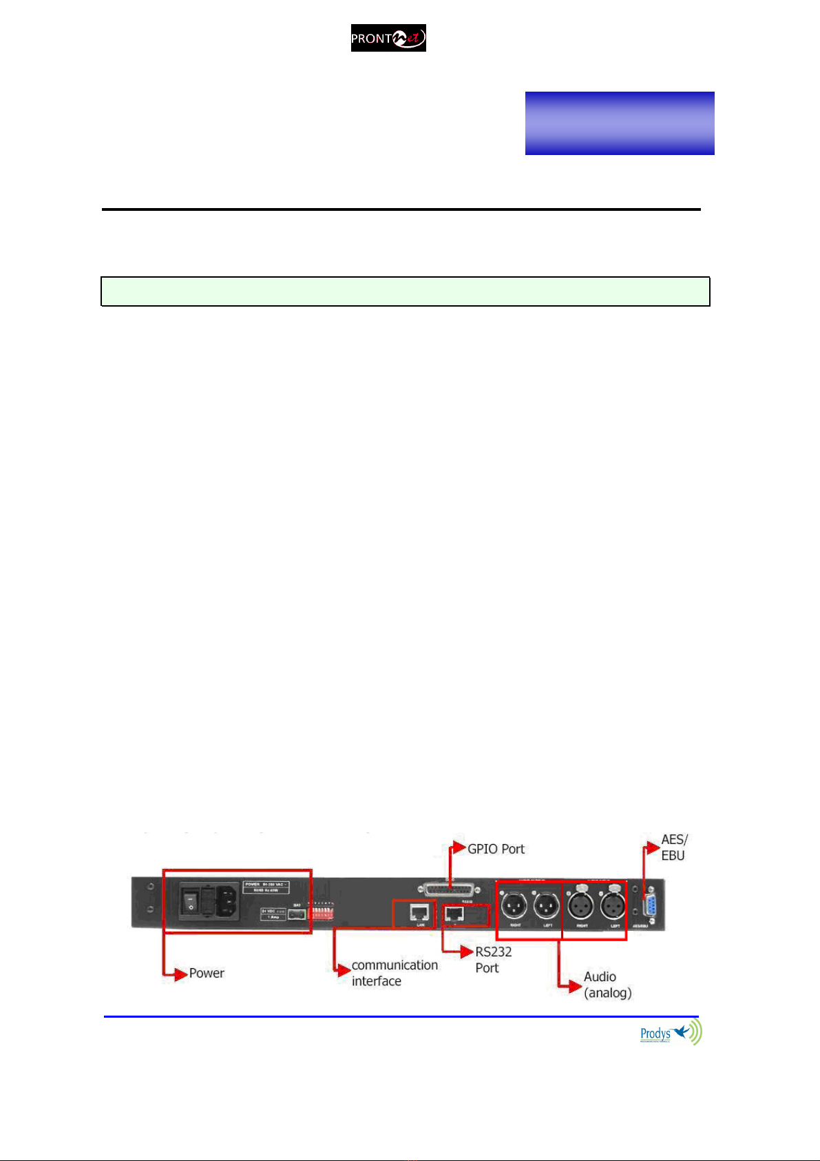
II.3 The rear panel
The majority of the connections of the ProntoNetLC are found on the back panel.
They are grouped together according to their function, as below:
Chapter II

ProntoNetLC User Manual
11
II.3.1 ower
On the back panel you will find the main power inlet. You will also find the main
power switch and the fuse holder. The ProntoNetLC unit is designed to take AC
universal power, from 100 to 240 VAC with frequency between 50Hz and 60Hz.
You will also find a fuse holder that holds two fuses, one for each phase of input.
When it is necessary to replace either fuse, it is important to make sure that it
complies with the technical specifications outlined below that will ensure
adequate protection.
Fuse requirements:
Fuse type: Type T
Amps 2A
Power 250V
ATTENTION – CHANGING THE FUSE
Disconnect the power cable BEFORE changing the fuse.
II.3.2 Ethernet port – the LAN Connector
The LAN socket is an standard 10/100Base-T (10/100 Mbps) Ethernet connection
that takes the typical RJ45 plug. Through this Ethernet port it is possible to
transmit and receive audio, as well as manage the equipment. Next to the
socket there are three LEDs that indicate different states for the connection and
these are very useful in problem-solving situations.
LAN LED’s:
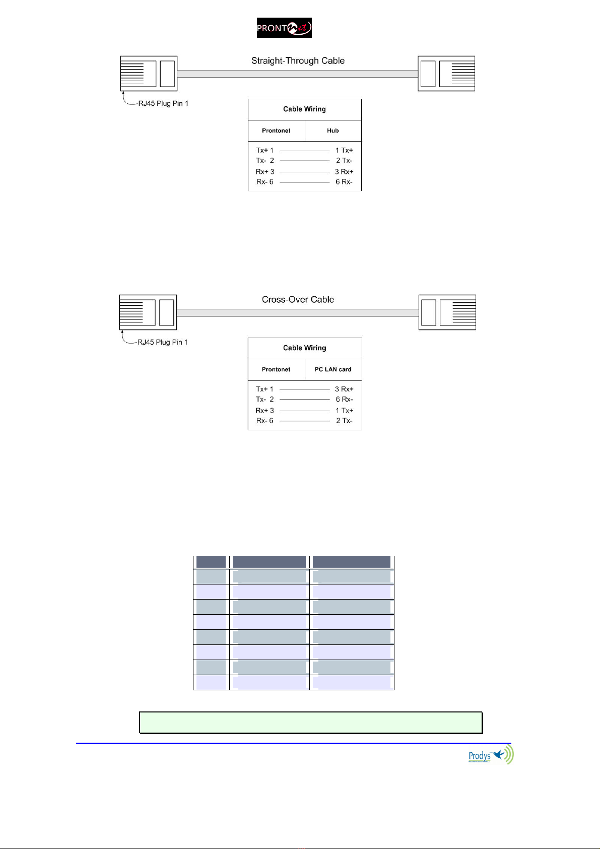
Connection to a Hub or Switch
In the majority of cases you can simply connect the unit’s LAN port to your
Ethernet network’s Hub or Switch using an Ethernet cable (CAT5). In this
case you should use a standard ‘straight-through’ Ethernet cable (not a
‘cross-over’ cable). This kind of cable can normally be found in any IT shop.
In any case, this cable is described in more detail below:
ProntoNetLC User Manual
12
Connection to a PC
In some cases, such as when you configure the equipment, it is possible
that you will want to connect the unit directly to a PC. In this case the PC
must have a free Ethernet port to connect to and you must use a ‘cross-
over’ Ethernet cable. Again, any good IT shop will stock these cables. This
time the wiring is as follows:
II.3.2.1. ISDN ort (Optional)
The ProntoNetLC incorporates an ISDN terminal adapter that allows connection
to a basic ISDN line (2B+D). It supports different ISDN protocols (EURO_ISDN,
DMS100, AT&T 5ESS and NAT1). To connect there are two RJ45 connectors: one
for connecting to an S/T interface and the other for connecting to a U interface.
Pin S/T Connector U Connector
1 NC NC
2 NC NC
3 Tx + NC
4 Rx+ RING
5 Rx- TIP
6 Tx- NC
7 NC NC
8 NC NC
The U connector is only available if an NT1 interface is installe .
ProntoNetLC User Manual
13
The NT1 interface is optional an is not supplie as stan ar .
When the ProntoNetLC is connected to a basic rate interface with bus
configuration and the unit is the termination point, it must be loaded with 100
Ohm resistors. These may be already fitted in the connection socket, if you do
not have external termination, the ProntoNetLC has jumpers available internally
that can be set to terminate the ISDN line. The jumpers are found next to the
RJ45 connectors.
P2 P3
100Ω RESISTORS CONNECTED
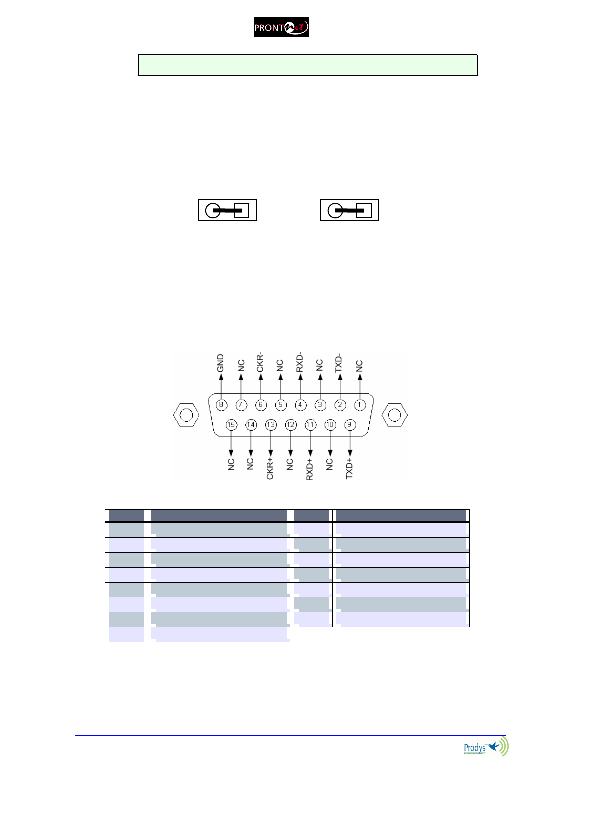
II.3.2.2. X21 ort
The 21 Port allows the transmission and reception of audio via a dedicated
digital connection. The socket is the standard 15 ways Sub-D with the following
connections:
Pin Function Pin Function
1 NC 9 Transmit Data TxD+
2 Transmit Data TxD- 10 NC
3 NC 11 Receive Data RxD+
4 Receive Data RxD- 12 NC
5 NC 13 Clock +
6 Clock - 14 NC (Internally use )
7 NC (Internally use ) 15 NC
8 GND
To connect a V35 port one must bear in mind the following correlation between
signals:

ProntoNetLC User Manual
14
Pin X21 ProntoNet V35 Signal
2 Transmit Data TxD- P
9 Transmit Data TxD+ S
4 Receive Data RxD- R
11 Receive Data RxD+ T
6 Clock - V
13 Clock+ X
II.3.3 RS 232 orts
There are two RS232 ports for use as auxiliary data ports. These ports allow the
transmission and reception of data along with encoded audio. Port A is always
ready. Port B is only available if the ProntoNetLC is configured as a DUAL Codec,
therefore able to operate two totally independent communication channels
1
.
Note that these sockets are RJ45 connections, as opposed to the typical 9-pin
sub-D connections. To make the conversion between RJ45 and RS232 there are
modular connectors available that should be wired as follows:
S-Cluster
RJ45
Connector
9-pin female
D-sub
Connector
1 (NC) 1
2 (Rx) 3
3 (GND) 5
4 (NC) 4
5 (NC) 6
6 (GND) 7
7 (Tx) 2
8 (NC) 8
1,4,5,8 must be unconnecte
The ports are always set to 8 DATA bits, NO parity, 1 START bit and 1 STOP bit.
The bit rate can be adjusted to between 300 and 9600 bps via software.
The ProntoNetLC acts as a DCE evice, therefore the connection to each of
the RS232 ports is wire in the following way:
1
DUAL codec: ProntoNetLC is able to operate as a DUAL codec over IP (when configured in
‘DOUBLE’ mode).
ProntoNetLC User Manual
15
ProntoNetLC – Pin 7 connector RJ45.........................Pin 2 PC
ProntoNetLC – Pin 2 connector RJ45.........................Pin 3 PC
ProntoNetLC – Pin 3,6 connector RJ45......................Pin 5 PC
The ProntoNetLC ignores har ware han shaking signals.
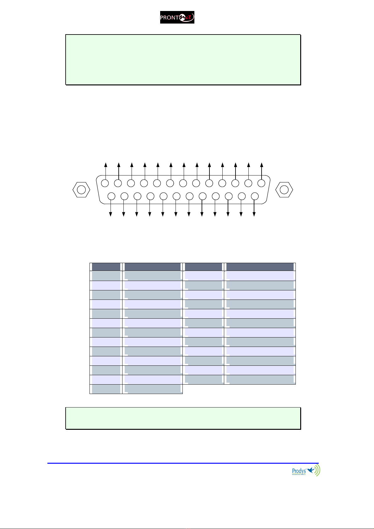
II.3.4 G IO ort
A Sub-D 25 ways socket provides a general purpose connection with 7 inputs
and 7 outputs. The connections must be wired according to the following
diagram:
12345
15
9 678
1617181920
10111213
25 24 23 22 21 14
NC
NC
NC
NC
OUT1
OUT3
OUT5
OUT7
NC
OUT2
OUT4
OUT6
GND
VCC
NC
IN2
IN4
IN6
NC
NC
IN1
GND
IN3
IN5
IN7
Pin unction Pin unction
1 +5VDC 14 IN 7
2 IN 6 15 IN 5
3 IN 4 16 IN 3
4 IN 2 17 IN 1
5 NC 18 NC
6 NC 19 NC
7 GND 20 GND
8 OUT 7 21 OUT 6
9 OUT 5 22 OUT 4
10 OUT 3 23 OUT 2
11 OUT 1 24 NC
12 NC 25 NC
13 NC
Pin 1 is connecte to +5 volts. If you nee it , run this power supply through
your evice with a resistor in series to limit the maximum current to 300 mA.

ProntoNetLC User Manual
16
II.3.4.1. Inputs
The inputs are active for grounding (active low).
II.3.4.2. Outputs
The outputs are “open collector”. They allow an output of 5VDC on one pin to
facilitate interconnection with the outputs. Each output supports up to a
maximum of 40VDC / 40 mA and will require a pull-up resistor to function with
other logic inputs. An appropriate value is 2.2 Kohms.
II.3.5 Audio interfaces
II.3.5.1. Analog audio I/O
The analog audio I/O is connected through the LR connections on the rear
panel. The wiring conforms to the following scheme:
Pin Función
1 Groun
2 Au io+
3 Au io-
These inputs and outputs are electronically balanced with a maximum
level of +22 dBu
2
.
II.3.5.2. AES/EBU Interface
An AES/EBU interface is available via the Sub-D 9 ways pin connector on the rear
panel of the unit. This connector provides the option to connect an externally
synchronised signal. The user can select via software if the digital output is to
synchronise with the audio input or with an external sync signal. The connector
is wired in the following way:
Pin unction Pin unction
1 AES/EBU IN - 6 AES/EBU IN +
2 GND 7 SYNC +
3 SYNC - 8 GND
4 GND 9 AES/EBU OUT +
5 AES/EBU OUT -
2
This is the default factory configuration. The maximum level on the inputs/outputs can be
configured to +4, +18 or +22dBu by setting some jumpers on the audio boards. Contact
support@prodys.net for more information.

ProntoNetLC User Manual
17
II.3.6 Microswitches
There are 8 microswitches on the back panel which are reserved for special
functions. Before turning on the unit the user must check that they are
configured according to the following diagram, which is the standard start-up
configuration:
Switch number 7 will restore the default factory configuration. The IP address is
changed to 192.168.100.100 and the netmask to 255.255.255.0.
ProntoNetLC User Manual
18
OK
The Front anel
The front panel of the ProntoNetLC has a display and keypads that allow you to
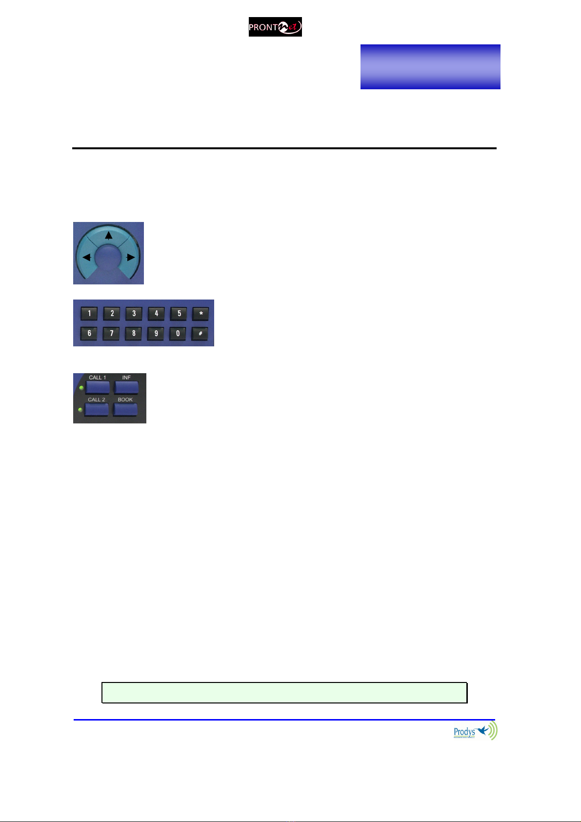
control and configure the unit. The keys are laid out in the following manner:
Navigation Keys: The keys ⇐
⇐⇐
⇐ , ⇑
⇑⇑
⇑ , ⇒
⇒⇒
⇒ , are used for moving
around the menus and the OK is for selecting/accepting the
desired action or parameter.
Number keypad: This numeric keypad is for
entering information such as the IP address that
you wish to connect to.
CONTROL Keys: There are several special keys grouped
together:
CALL1 and CALL2 are for establishing and terminating
connections, and also to monitor the called/calling number.
INF is for viewing status information.
BOOK for establishing communications using a configuration
saved in the Address Book.
III.1 DIS LAY
To help explain the ProntoNetLC DISPLAY we should distinguish between the
status screen and the menu screen:
The status screen shows information about the communication lines and
the status of the Decoder.
The Menu screen shows the different configuration menu options and is
only displayed when you press OK on the navigation menu keys.
III.1.1 STATUS SCREEN
This is the default screen that you will see when the ProntoNetLC is ‘at rest’, that
is, when you are not navigating or using the front panel keys. It reports the
status of the communications and the Decoder.
More information about this in the following sections.
Cha
pter III

ProntoNetLC User Manual
19
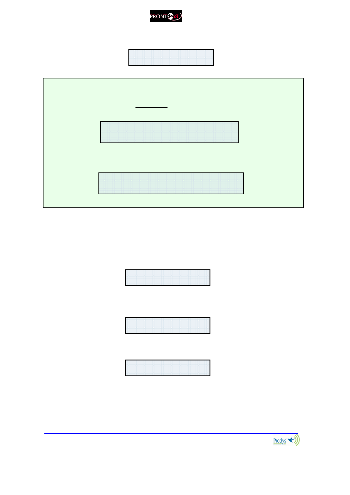
The display will show information in the following way:
The first line shows information about the status of communication Line 1 (Tx),
and the second line shows information about the status of communication Line 1
(Rx), followed by the status of the decoder of line 1.
The communication lines will be in one of the following states:
DOWN: The communication line is not physically detected. Most likely the
interface is not plugged in. The Display shows “DOWN”:
IDLE: The line is detected physically but no connection is being made. The
display shows IDLE and the disconnection code:
Tx CONNECTED: The Tx part of the line is connected. The display shows
“Connected.
Rx CONNECTED: The Rx part of the line is connected. The display shows
“Connected” and the Decoder status:
CALLING: In the process of making a connection. The display shows an
arrow indicating outgoing calling and the IP address:
The Decoder can be in one of the following states:
RAMED: Audio Synchronised. The displays shows the word “FRAMED”:
L1:CONNECTED RAMED
L2:DOWN
Status Tx
and Rx
Line 1
Status
Decoder 1
TX:DOWN
RX:DOWN
TX:IDLE(0)
RX:IDLE (0)
TX
-
>CONNECTED
RX:CONNECTED RAMED
TX
1234567890
RX:IDLE(4)
TX:IDLE(0)
RX:CONNECTED RAMED
TX
-
>
CONNECTED
RX: CONNECTED RAMED
ProntoNetLC User Manual
20
SEARCH Searching for synchronisation. The displays shows the word
“SEARCH”:
The Deco er status information only appears if the line is connecte .
If the line is showing an IDLE status, an in icator co e will show the cause of the
last isconnection below. In Appen ix B you will fin explanations for each of these
co es.
When the lines are connecte the irection of the arrow will in icate if the unit ma e
or receive the connection.
When ProntoNetLC is configured to DOUBLE mode over IP, there will be
two lines and the unit will work as a DUAL codec, that is, two independent
communications. To access the information about line 2, the user has to press
the right and left arrow keys on the front panel. An arrow on the right or on the
left side of the screen will inform the user about this situation.
If the user presses the right arrow key on the front panel, the display will show
the information related to the second line.
If the user presses the left arrow key on the front panel, the display will show
the information related to the first line again.
L 1 : I D L E ( 0 )
I P
L 2 : N O T A V A I L A B L E
L1:CONNECTED SEARCH
L2:DOWN
TX1:IDLE(0)
RX1:IDLE (0) >>
TX2:IDLE(0)
RX2:IDLE (0) <<
TX2:IDLE(0)
RX2:IDLE (0) <<
L 1
C O N N E C T E D F R A M E D
L 2 : N O T A V A I L A B L E
Table of contents
Other Prodys Conference System manuals


Popular Conference System manuals by other brands


GlobalMedia
GlobalMedia USB3.0 HD Video Conferencing Camera user manual

Cisco
Cisco TelePresence DX80 Quick reference guide

Polycom
Polycom RealPresence Immersive Studio Administrator's guide

Yealink
Yealink MeetingSpace VC500 quick start guide

Cisco
Cisco CTS-3010 Administration guide

Close Talk
Close Talk Close Talk Conference System installation instructions


