Prodys PortaNet User manual


PortaNet User Manual 2 of 156
INDEX
CE Declaration of Compliance.................................................. 8
About this manual ............................................................... 9
General specifications .........................................................10
Installing the PortaNet.........................................................11
III.1 PortaNet overview 11
III.1.1 Control Panel 11
III.1. The front panel and its connectors 14
III.1.3 Rear Panel 15
III.1.3.1 Fourth MIC/ INE audio input (in 4). ....................................15
III.1.3. Second auxiliary line level output. .....................................15
III.1.3.3 Auxiliary data: GPIO and RS232 ports. .................................16
III.1.3.4 Ethernet port – the AN Connector .....................................16
III.1.3.5 ISDN Port....................................................................17
III.1.3.6 Power supply ...............................................................17
PortaNet audio inputs..........................................................19
IV.1 ocation 19
IV.2 Technical specifications 19
IV. .1 MIC/ INE level inputs 19
IV. . International Sound INE level input. 19
IV.3 Audio evel Controls 20
IV.4 Audio input configuration 20
IV.4.1 ON keys 20
IV.4. TB Keys 20
PortaNet audio Outputs .......................................................
V.1 ocation 22
V.2 Headphone outputs. 22
V. .1 Technical specifications 22
V. . Operation mode – Headphones Matrix 22
V. . .1 Attenuation when the MIC/ INE level input goes to Talkback or
Program................................................................................24
V. . . Enable from TB Key........................................................24
V.3 ine level balanced audio output: REC 25
V.3.1 Technical specifications 25
V.3. Operation Modes 25
V.3. .1 Codec Mode .................................................................26
V.3.3 RECORDING operation mode 26
V.4 ‘AUX’ output. 27

PortaNet User Manual 3 of 156
V.4.1 Technical specifications 27
V.4. Operation modes 27
V.4. .1 CODEC mode ................................................................28
V.4. . INTERCOM mode............................................................28
V.4. .3 Other configurations for the Intercom mode ..........................28
PortaNet audio presets ........................................................ 9
VI.1 What is an audio preset? 29
VI.2 Creating & Modifying a preset 30
VI.3 oading a preset 31
Operation guide .................................................................3
VII.1 Starting the unit 32
VII.2 Checking the configuration – the inf key 32
VII.3 Selecting the communication interface 33
VII.4 Configuring the communication interface 34
VII.4.1 Configuring the ISDN Terminal adapter 34
VII.4. Configuring the AN port 35
VII.5 Checking the communication interfaces 35
VII.6 Connecting PortaNet to the line 35
VII.7 Audio checking 36
VII.8 Selecting the compression algorithm 37
VII.9 Decoder operation 37
VII.10 Calling from PortaNet 37
VII.10.1 CA 1, CA 2 and Phone Book keys 38
VII.10.1.1 Establishing a call when PortaNet is configured as an IP
Unicast/Multicast codec.............................................................39
VII.10.1. Establishing a call when PortaNet is configured as an IP Multi-
Unicast codec (NET = IP) ............................................................40
VII.10.1.3 Establishing a call when PortaNet is configured as an ISDN codec
(NET = ISDN)...........................................................................41
VII.11 Calling from the Phone Book 41
VII.12 Incoming calls 42
VII.1 .1 Receiving ISDN calls 42
VII.1 . Incoming calls via IP 43
PortaNet remote control ......................................................45
VIII.1 Getting Started 48
VIII.1.1 Extra Options in the ogin Dialog Box 50
VIII.2 General configuration 51
VIII. .1 Interfaces 51

PortaNet User Manual 4 of 156
VIII. .1.1 AN port...................................................................51
VIII. .1. ISDN Terminal adaptor Configuration.................................56
VIII. .1.3 RS232 Port ................................................................58
VIII. .1.4 GPIO Port..................................................................58
VIII. . System Configuration 61
VIII. . .1 TimeDate..................................................................64
VIII. . . Password ..................................................................64
VIII. . .3 Aux Data ..................................................................65
VIII. . .4 Software Versions........................................................ 66
VIII. . .5 Alarms ..................................................................... 66
VIII. . .6 Backup.....................................................................67
VIII. . .7 Phone Book ...............................................................67
VIII. . .8 Scheduler .................................................................68
VIII. . .9 Advanced..................................................................68
VIII. . .10 Exporting / Importing the configuration............................69
VIII. .3 Streaming 69
VIII. .3.1 Protocol ...................................................................70
VIII. .3. Tx ..........................................................................70
VIII. .3.3 Rx ..........................................................................73
VIII. .3.4 Test ........................................................................73
VIII. .3.5 Real Time Monitoring....................................................75
VIII.3 Call og 76
VIII.4 Keypad locking 78
VIII.4.1 ocking the keypad from the Portanet keyboard 79
VIII.5 Audio control keypad 79
VIII.6 Scheduler 80
VIII.6.1 Configuration 80
VIII.6. How to enable/disable the Scheduler 80
VIII.6.3 Automatic and manual call 81
VIII.6.4 Programming the scheduler 81
VIII.6.5 Name 82
VIII.6.6 Start 82
VIII.6.7 Priority 82
VIII.6.8 End 82
VIII.6.9 Scheduled call configuration 85
VIII.6.9.1 Manual configuration ....................................................85
VIII.6.9. Automatic configuration from the phone book......................86
VIII.6.10 Modifying existing scheduled calls 86
VIII.6.11 Deleting existing scheduled calls 86
VIII.6.1 Copying and pasting scheduled calls 86
VIII.6.13 Monitoring scheduled calls 87
VIII.7 Controlling the PortaNet 88
VIII.7.1 Selecting the NET interface 88
VIII.7. Configuring the Encoder 88
VIII.7.3 Making calls: 89
VIII.7.4 Disconnecting the ine 92

PortaNet User Manual 5 of 156
VIII.7.5 ine Status 92
VIII.7.6 Decoder Status 93
VIII.8 Alarms 94
VIII.8.1 Selecting Alarms 94
VIII.8. Monitoring Alarms 96
VIII.8.3 Alarms History 96
VIII.8.4 Alarms Notification 97
VIII.8.4.1 SNMP traps................................................................97
VIII.8.4. Email.......................................................................98
How does the PortaNet work?................................................99
IX.1 Selecting the communications interface 99
IX.2 Configuration parameters that are dependant on the network type
selected 99
IX.3 PortaNet working as a “DUA CODEC” over ISDN 100
IX.4 PortaNet working as a “DUA CODEC” over IP 101
IX.5 About how the Decoder works and automatic searching 102
IX.6 The PortaNet operating as IP codec (Proprietary Protocols) 104
IX.6.1 UNICAST communications 104
IX.6. Using line 2 104
IX.6.3 Establishing a UNICAST connection from the PortaNet 105
IX.6.4 Establishing a MU TICAST communication from the PortaNet 105
IX.6.5 MU TI-UNICAST 107
IX.6.6 Prodys Proprietary set of protocols 108
IX.6.7 Proprietary (set of protocols) v2 109
IX.6.8 PRODYS PORTS for Prodys Proprietary protocols (v1 & v2) 111
IX.7 SIP 111
IX.8 SAP 113
IX.9 PortaNet operating as an ISDN codec 116
IX.9.1 Establishing ISDN calls 117
IX.9. Receiving calls via ISDN 117
IX.9.3 Restrictions in ISDN communications 118
IX.10 How the backup mode works 119
IX.10.1 MASTER & S AVE Configuration 119
IX.10.1.1 PortaNet MASTER operation.......................................... 120
IX.10.1. PortaNet S AVE operation ............................................ 122
PortaNet Blocks ............................................................... 1 4
X.1 Communications 124
X.2 Audio MIC/ INE inputs 125
X.3 Audio “International Sound” input 126
X.4 Audio outputs 126

PortaNet User Manual 6 of 156
X.4.1 Headphone outputs 127
X.4.1.1 Attenuation when the MIC/ INE level input goes to Talkback or
Program.............................................................................. 128
X.4.1. Enable from TB Key...................................................... 129
X.4. Balanced audio outputs. 129
Operation examples.......................................................... 130
XI.1 Using the TalkBack channel 130
XI.2 Connecting to an external mixer 132
XI.3 Stereo operation mode: 134
Problem-solving guide ....................................................... 136
XII.1 Audio problems 136
XII.1.1 No Audio on the outputs 136
XII.1. The program line is connected but there is no audio on the outputs136
XII.1.3 There is no audio output at either end 137
XII.1.4 Audio distortion 137
XII.2 ISDN communication problems 137
XII. .1 Unit cannot make outgoing calls 137
XII. . Unit cannot receive incoming calls 138
XII.3 IP communication problems 138
XII.3.1 Prodys Codec’s Web Page cannot be accessed 138
XII.3. When connecting two audiocodecs in unicast, there is no audio at
one end. 141
XII.3.3 No audio when connecting two audiocodecs using Multicast 142
XII.3.4 Interruptions to audio when connecting two Prodys Codecs. 142
Technical specifications ..................................................... 145
Audio Interfaces 145
Audio Compression 146
BANDWIDTH (KHz) 146
IP Protocols and compatibility 149
Comunication ports 149
ISDN 149
AN port 149
GPIO port 149
RS232 port 149
Power supply. 149
Weight and dimensions 150
Connectors ..................................................................... 151
XIV.1 Audio inputs 151

PortaNet User Manual 7 of 156
XIV.2 Headphone outputs 151
XIV.3 Aux output 151
XIV.4 Rec output 151
XIV.5 AN port 152
XIV.5.1 Connecting to a HUB or SWITCH 152
XIV.5. Connecting to a PC 152
XIV.6 RS 232 port 153
XIV.7 GPIO Port 153
Updating the firmware....................................................... 154

PortaNet User Manual 8 of 156
CE Declaration of Compliance
Procesamiento Digital y Sistemas S.L., hereby declares that PortaNet bearing the
CE16 X marking is in compliance with Electromagnetic Compatibility Directive
( 9/336/EEC), and the Low Voltage Directive (72/23/EEC) of the European
Union.
A “Declaration of conformity” for PortaNet is available on file at Prodys offices in
Spain. To obtain this information, please email [email protected].
CAUTION
PortaNet uses a Lithium battery.
Danger of explosion if battery is incorrectly replaced. Replace only with the same
or equivalent type recommended by the manufacturer. Dispose of used batteries
according to the manufacturers instructions.
Your product is designed and manufactured with high quality
materials and components, which can be recycled and reused.
When this crossed-out wheeled bin symbol with black bar underneath
is attached to a product it means that product is covered by the
European Directive 2002/96/EC.
Please, inform yourself about the local separate collection system for
electrical and electronic products.
Please act according to your local rules and do not dispose of your old
products with your normal household waste. The correct disposal of
your old product will help prevent potential negative consequences for
the environment and human health.

PortaNet User Manual 9 of 156
About this manual
This manual is the installation and operation guide for Portanet. With this
manual, the user will gain a fundamental understanding about the main features
and operation modes.
This manual is arranged in the following manner:
1. PortaNet general specifications.
2. Installing the PortaNet.
3. Operation guide.
4. Remote control.
5. PortaNet blocks.
6. How it works.
7. Examples of applications.
. Problem-solving guide.
9. Technical specifications.
10. Connectors.
11. Updating the firmware.

PortaNet User Manual 10 of 156
General specifications
PortaNet is the first really portable audio codec which provides real time audio
communications over IP networks. In addition, it comes fitted with an 1-BRI
ISDN interface, which allows ISDN connectivity at those places where IP is not
available.
PortaNet, as a member of the Prodys IP audio codec family, includes all the
features of the ProntoNet, but adds some important enhancements in the audio
interfaces and operationally for portable use.
These are the PortaNet most important features:
Analog Audio: PortaNet incorporates a mixer with four MIC/LINE
level configurable audio inputs and an extra line level input that can be
mixed to the headphone outputs to provide the international sound to
the commentators. It also includes three headphone outputs and two
line level analog balanced audio outputs. All the outputs can be
configured by the user to suit the audio signal to be carried, to adapt
to the needs of different applications.
Compression algorithms: PortaNet is equipped with the widest
range of compression algorithms without any additional cost: G711,
G722, PCM, MPEG1,2 Layer II, Mpeg 1,2 Layer III, MPEG 2,4 AAC LC,
MPEG4 AAC LD, MPEG4 AAC HE, Standard and Enhanced apt-X™.
Communications: IP and ISDN connectivity. With PortaNet it is
possible to establish two independent connections, one for program
and the other for coordination.
Power supply: Desk Top AC/DC Power Converter and an optional
battery which provides 3 hours of autonomy. The battery can be
charged on the system and its status can be monitored on the screen.
Au iliary data: PortaNet includes a serial port (RS232) and a GPIO
port with 2 inputs and 2 outputs. The auxiliary data can be
sent/received along with the audio for remote control/signalling.
Control and monitoring: The unit can be configured from its front
panel and from its embedded web page. All the controls are
configurable remotely. The keypad can be controlled and also blocked
from the web page for security reasons.
Small and lightweight: its weight is about 2 kg. and its dimensions
are: 70 x 2 5 x 243 mm.
PortaNet User Manual 11 of 156
Installing the PortaNet
Before unpacking unit check its packaging for any signs of amage or
mishan ling uring transportation, report any amage to the shipping
company imme iately. Unpack the unit carefully, if you fin any amage or
the unit oes not work correctly, you shoul contact Pro ys or its istributor
as soon as possible.
III.1 PortaNet overview
PortaNet has all its connections in its front and rear panels. The keypads and
display are placed in the top surface.
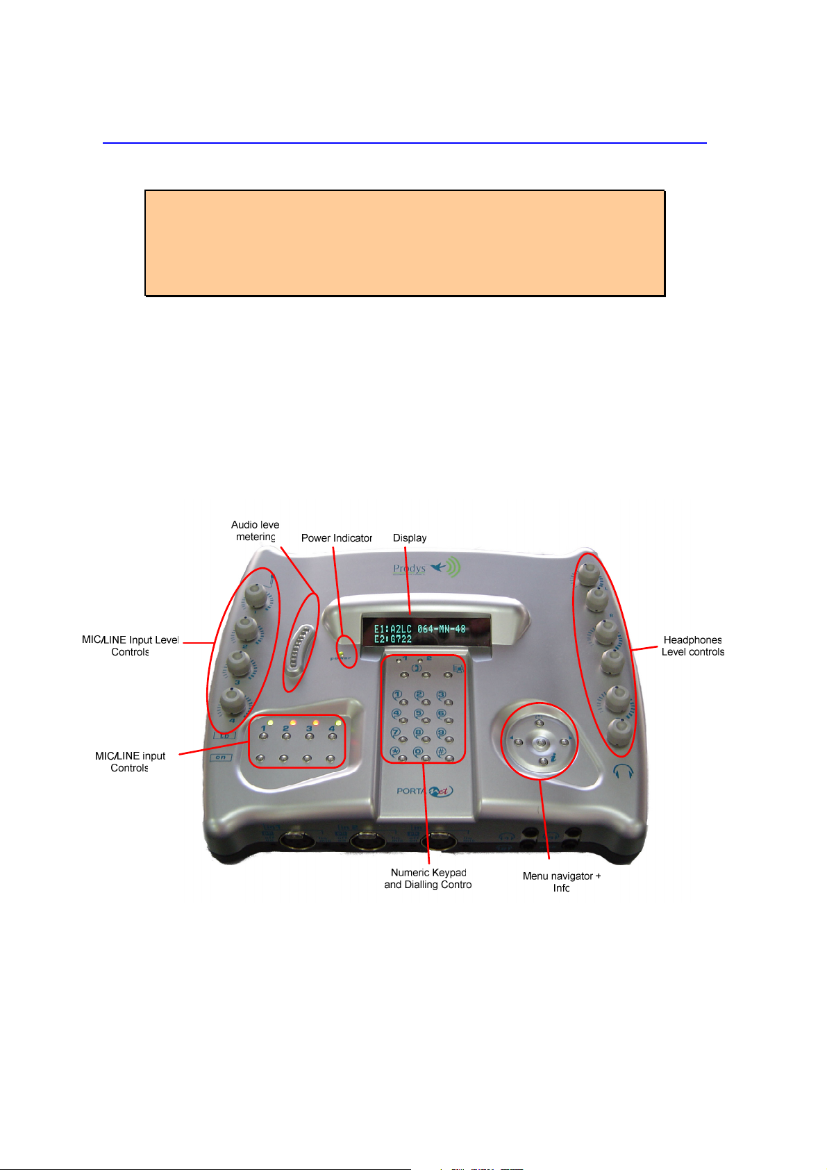
III.1.1 Control Panel

PortaNet User Manual 12 of 156
Audio Level controls for the MIC/LINE inputs
Each audio input can be adjusted independently. The audio level control can be
made locally or remotely by using the PortaNet web browser.
Audio Level controls for the headphone outputs
The headphone audio level can be adjusted independently for each ear. It is
possible to monitor different signals on either side of the headphones.
Menu Keypad
Navigation Keys: The keys ⇐
⇐⇐
⇐ , ⇑
⇑⇑
⇑ , ⇒
⇒⇒
⇒ , are used for
moving around the menus and the OK is for
selecting/accepting the desired action or parameter.
Inf key
This key allows the user a simple and quick way to display detailed information
on the status and configuration of the PortaNet.
Call management keypad.
The numeric keypad is for entering information such as the
IP address or ISDN number that you wish to connect to.
BOOK for establishing communications using a
configuration saved in the Address Book.
CALL1 and CALL2 are for establishing and terminating
connections, and also to monitor the called/calling
number.

PortaNet User Manual 13 of 156
Input audio control keypad.
On Key Each audio input has a key to
enable/disable it. When an audio input is
enabled, it is connected to the program
line (line 1).
Tb Key PortaNet allows the user to establish two independent
communications, using either IP or ISDN. Each input can be configured to be
sent through the program line (line 1) or through the coordination or TalkBack
line (line 2). Pressing the Tb key for one input causes this input to be mixed with
those signals assigned to the coordination or TalkBack line (line 2).
LED´s
There is a led related to the status of each input:
•OFF: Input disabled.
•Green: Input enabled and connected to the program line (line 1).
•Red: Input enabled and connected to the TalkBack line (line 2).
Power LED
It shows the power supply status and also battery status.
-GREEN: The external power converter is powering the unit. The battery is
not connected.
-BLINKING ORANGE: The external power converter is powering the unit.
The battery is connected and it is being charged on the system.
-ORANGE: The external power converter is not powering the unit. The
battery is connected and powering the unit.
-BLINKING RED: The external power converter is not powering the unit.
The battery is connected and powering the unit, but it is about to run out
(about 20 minutes / 10% of battery capacity).
When the unit is starting, the Power LED will be blinking green.
PortaNet User Manual 14 of 156
III.1. The front panel and its connectors
In the front panel there are two areas: Audio inputs and Headphone outputs.
Because of space restrictions the Auxiliary output level control is also there.
There is an additional fourth input in the rear panel. This
input doesn’t have an associated headphone output.
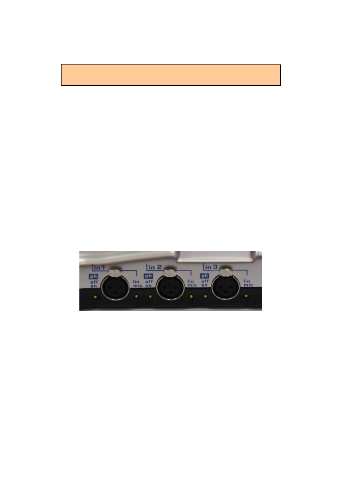
MIC/LINE Audio inputs: There are four MIC/LINE audio inputs. Each audio input
includes a switch to select MIC or LINE level, and another one for selecting
whether to supply 4 volts. phantom power to the MIC.
line/mic switch:
When this switch is in the UP position, the line level input is
selected (maximum input level +20 dBu).
When this switch is in the DOWN position, this input is
configured to work as a MIC level input.
ph swtich(4 volts. Phantom powered):
When this switch is in the UP position (OFF), this option is
disabled.
When this switch is in the down position (ON), this option is
enabled.
Headphone outputs: There are three headphone outputs, each one related to
its corresponding audio input. Signals present on the headphone audio outputs
will be dependent on the configuration of the audio headphone matrix available
in the PortaNet web browser. More information about it in next chapter about
PortaNet’s input and outputs.
There are audio level controls for each output and for each ear.
Line level balanced auxiliary audio output: Along with the three headphone
outputs, there is a fourth output called ‘aux’. This audio output is totally
independent from the headphone outputs, and it is placed together with these
only for space saving reasons. This output is a balanced line level output, with a

PortaNet User Manual 15 of 156
maximum level of +20 dBu. This output is user configurable; that means that it
is possible to define which audio signals will be present in this output.
Further information about audio output configuration can
be obtained from chapter 5 - PortaNet Blocks.
III.1.3 Rear Panel
The rest of connections are located on the rear panel:
III.1.3.1 Fourth MIC/ INE audio input (in 4).
The same as the inputs from the front panel, it can be configured as LINE or MIC
level, and it has the possibility to be phantom powered (4 volts.) However, it
doesn’t have a headphone output related. For this purpose, the ‘aux’ output
might be used.
III.1.3.1.1 INE level input (International Sound Input – Int. in)
This is an additional line level input which can be mixed with the headphone
outputs to provide the international sound to the commentators.
III.1.3. Second auxiliary line level output.
Called REC output, this output can carry the program line signal, the return from
the program line or the sum of both signals. This is a balanced XLR connector.
Further information about audio output configuration
can be obtained from chapter 5 - PortaNet Blocks.

PortaNet User Manual 16 of 156
III.1.3.3 Auxiliary data: GPIO and RS232 ports.
The GPIO port on a DB9 connector allows remote
control/signalling by means of remote contact closures.
There are two ground contact inputs and two relay
outputs.
Another DB9 connector at the rear panel provides an
RS232 port for sending/receiving auxiliary data along
with the encoded audio for IP and ISDN
communications.
Over ISDN, the auxiliary data and GPIO information will be only available in
those compression algorithms which support ancillary data along with the
encoded audio, and when this option is enabled.
Over ISDN, it is possible to choose between ProntoNet format and Pronto2/3
format (in which the GPIOs information cannot be sent). To be backward
compatible with ISDN Pronto2/3 Prodys devices, select Pronto2/3 format.
When selecting IP as communication interface, the auxiliary data can be sent via
a different path, different from the audio one. This method has 3 big
advantages: less delay independent from the audio codification delay; the
possibility to send/receive auxiliary data regardless of the compression mode
used for the audio communication; and the possibility to send/receive the User
bit of the AES/EBU frame. The drawback is that the audio and data delay won’t
be the same.
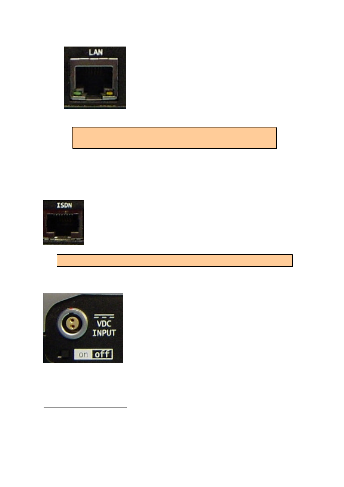
III.1.3.4 Ethernet port – the AN Connector
The LAN socket is an standard 100Base-Tx (10/100 Mbps) Ethernet connection
that takes a RJ45 plug. Through this Ethernet port it is possible to transmit and
receive audio, as well as manage the equipment. Next to the socket there are
three LEDs that indicate different states for the connection and these are very
useful in problem-solving situations.
LAN LED’s:
PortaNet User Manual 17 of 156
Green LED LINK STATUS: ON = Connected
Orange LED RECEIVE STATUS: On =
Receiving Data.
Further information can be obtained in the chapter -
XIV - Connectors.
From the web interface and the front panel menu it is possible to set the speed
and duplex configuration to the following values: AUTO, 10HD, 10FD, 100HD,
100FD
1
.
III.1.3.5 ISDN Port
The PortaNet incorporates an ISDN terminal adapter that allows
connection to a basic rate ISDN line (2B+D). It supports different
ISDN protocols (EURO_ISDN, DMS100, AT&T 5ESS and NAT1).
There is one RJ45 connector for connecting to an S/T interface
S/T (S
0
).
There is available a special version with U ISDN interface.
III.1.3.6 Power supply
PortaNet comes supplied with a desk top AC/DC
converter (16 volts. output) to be connected to the
power connector located at the rear panel. The
power converter works with an AC input range of 100
to 240 VAC, 50 to 60 Hz.
The power switch is located just below the power
connector.
In addition, there is also available an optional custom
battery pack. Whenever the external power converter
is connected, the power is supplied from it, and the battery will be charged when
necessary. When the external power converter is unplugged from the unit, the
battery will take over.
1
This option is available from version 5.2.1 onwards.

PortaNet User Manual 18 of 156
The power LED on the upper panel informs about the status of the battery and
the power supply. These are the possible status for this led:
-GREEN: The external power converter is powering the unit. The battery is
not connected.
-BLINKING ORANGE: The external power converter is powering the unit.
The battery is connected and it is being charged on the system.
-ORANGE: The external power converter is not powering the unit. The
battery is connected and powering the unit.
-BLINKING RED: The external power converter is not powering the unit.
The battery is connected and powering the unit, but it is about to run out
(about 20 minutes / 10% of battery capacity).
Once the unit is switched on, the boot sequence will start. This sequence will
take about 50 seconds to finish, when the screen will display the status display.
When the unit is starting, the Power LED will be blinking green.
PortaNet User Manual 19 of 156
PortaNet audio inputs
IV.1 Location
There are four MIC/LINE level inputs, switchable between LINE and MIC level.
Three of them are located on the front panel, and the fourth one is on the rear
panel. Moreover, there is an additional line level input located on the rear panel
which can be mixed to the headphone outputs.
IV. Technical specifications
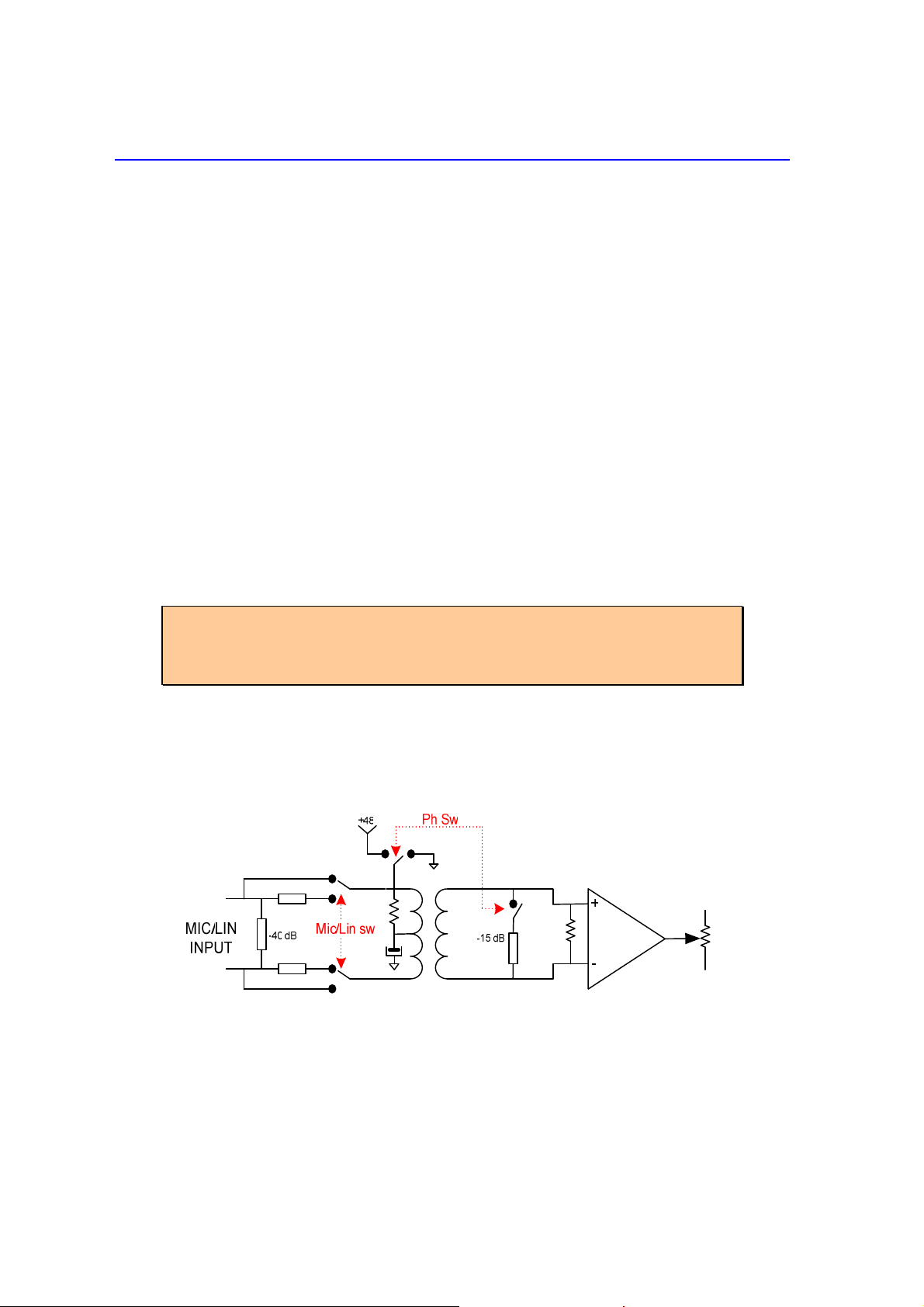
IV. .1 MIC/ INE level inputs
All the MIC/LINE level inputs are transformer balanced on a XLR female
connector. These inputs are switchable between MIC and LINE levels by
means of a switch placed on the right side of the input connector.
It is possible to supply phantom power (4 volts.) to each input. There is
a switch on the left side of the input connector for this purpose.
When the audio inputs are configured as MIC level inputs, sensibility
range is –60 to –25 dBu.
When phantom power is enabled, the whole gain is decreased by 15
dB to compensate for the the higher output of condenser MICs.
Thus, the gain range will go from –45 to –10 dBu.
When the inputs are configured as LINE level inputs, the maximum input
level will be +20 dBu.
Each input level can be adjusted independently.
IV. . International Sound INE level input.
Electronically balanced on a XLR female connector.
Maximum input level is +20 dBu

PortaNet User Manual 20 of 156
IV.3 Audio Level Controls
Each audio input can be adjusted independently. The audio level control can be
made locally from the knobs or remotely by using the PortaNet web browser.
Once the audio input gain setting has been selected to be controlled by remote
control, the PortaNet reminds this effect on its display upon any attempt to
increase or decrease the audio gains locally by means of the audio control knobs.
The International Soun Input level can be a juste only remotely.
IV.4 Audio input configuration
IV.4.1 ON keys
Each audio input has a key to enable/disable
it. When an input is enabled, it will contribute
to the audio sent through the program line
(line 1). The corresponding LED will light on
GREEN, indicating that the input is enabled
and going through the line 1.
IV.4. TB Keys
PortaNet supports two independent communications via IP or ISDN. Thus, we
can establish one connection for the main program, and another one for
coordination, or TalkBack program. Each input can be configured to be added to
the audio contribution on line 1 or line 2 by means of the ‘TB’ and ‘ON’ keys
located on the top surface.
When an input is connected to line 2 or TalkBack program (pressing the
Tb key) it is disconnected from the program line (line 1). The
corresponding LED will light on RED.
When an input is connected to line 1 or program (pressing the ON key)
it is disconnected from the TalkBack line (line 2). The corresponding
LED will light on GREEN.
When the input is disabled, the led is off.
Table of contents
Other Prodys Conference System manuals


Popular Conference System manuals by other brands


Lucent Technologies
Lucent Technologies MERLIN LEGEND Release 6.1 System programming and maintenance

Cisco
Cisco TelePresence SX10 user manual

Aastra
Aastra S850i Installation and quick start guide

Spintso
Spintso REFCOM PRO quick guide

Biamp
Biamp TesiraFORTÉ AVB VT4 System design guide

Cisco
Cisco 3545 Serial overview

Beyerdynamic
Beyerdynamic MCS-D 200 operating instructions

Avaya
Avaya CU-360 Release notes

StarLeaf
StarLeaf GTm 5140 Installation and Admin Guide

Lenovo
Lenovo THinkVision T75 Faq

AT&T
AT&T MERLIN LEGEND Release 2.0 Analog Multiline... System programming and maintenance

Zimmer
Zimmer SCM Series Installation and operating instructions