PROF SVAR TMB PS 027 Instruction Manual

AUDI A1 (5/2010 )
ŠKODA Fabia II (2006 )
ŠKODA Fabia II Combi
(2007 )
Montage und Bedienungsanleitung
User’s guide and installation instructions
TMB PS 027
ANHÄNGERKUPPLUNG
für Personenkraftwagen mit demontierbarem Kugelhals
TRAILER COUPLING DEVICE
for passenger cars with removable tow arm
e8 * 94/20 * 0064
© 28.4.2011
2
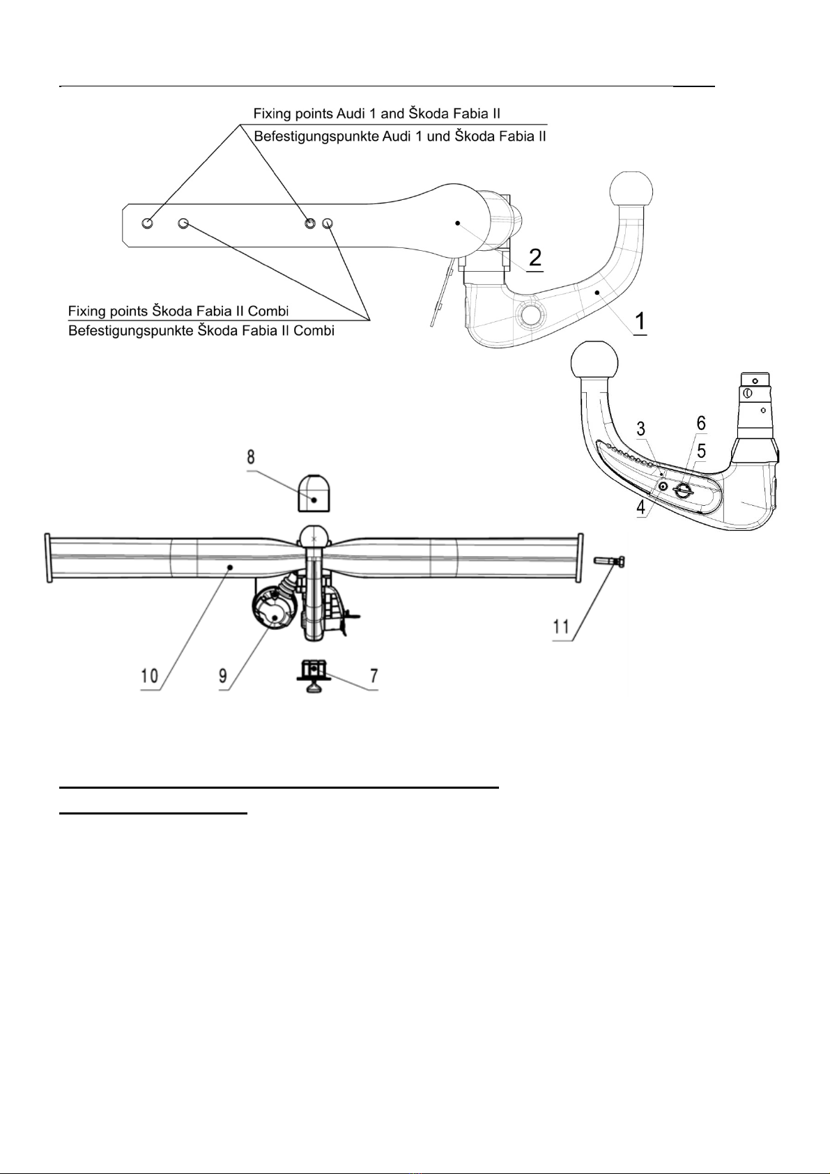
Verzeichnis der Teile der Anhängerkupplung:
List of components:
Bezeichnung des Teils, Name of the part Stück, Quantity Position, Positon
Kugelhals (Towing arm) 1 1
Spannhülse (Clamping bush) 1 2
Betätigungshebel (Control lever) 1 3
Sicherungsstift (Safety pin) 1 4
Schloss des Betätigungshebel (Lock of the control lever) 1 5
Schlüssel(Key) 2 6
Abdeckung der Spannhülse (Clamping bush) 1 7
Kugelbolzendeckel (Cover of the ball) 1 8
Steckdose (Socket) 1 9
Träger vollständig (mit Identifikationsschild)
Beam assembly (with ID plate) 1 10
Schraube (Bolt) M10 x 35 4 11
Selbstklebeetikette (Self-adhesive sticker) „50 kg“ 1 -
Bild / Figure

3
ANHÄNGERKUPPLUNG
Typ TMB PS 027
Die Anhängerkupplung Typ TMB PS 027 ist für das Ankuppeln von Anhängern mit einer Masse bis
1200 kg an die Pkw AUDI A1, ŠKODA Fabia II und ŠKODA Fabia II Combi bestimmt.
Allgemeine Angaben
Die Konstruktion der Einrichtung entspricht der Verordnung des Ministeriums für Verkehr der CR,
sowie auch allen anderen relevanten nationalen und internationalen Vorschriften. Der Zugarm ist mit
einem Kugelbolzen von Durchmesser 50 mm laut dem Standard ISO 3853 versehen. Die Vorrichtung
wurde auf Festigkeit laut der europäischen Richtlinie 94/20/EG geprüft.
Parameter
Max.Anhängermasse, gebremst 1200 kg
Max.Anhängermasse, ungebremst 500 kg
Nur für ŠKODA Fabia II Combi 450 kg
Es gilt die Gewichtseinschränkung gemäß des Fahrzeugszulassungsscheines!
Stütztlast 50 kg
Durchmesser des Kugelbolzens 50 mm
DC-Wert 7,2 kN
C
T
CT
gDC
g – Fallbeschleunigung (g = 9,81 ms-2)
T – Gewicht des Zugfahrzeugs [t]
C – Anhängergewicht [t]
AHK Gesamtgewicht 15,1 kg
Maße 960 x 620 x 205 mm
Hinweis
Zum Einbau der Ahängerkupplung für Škoda Fabia II und Škoda Fabia II Combi müssen noch zusätzlich
folgende Bauteile bestellt werden (Die Bezeichnung in Klammern – siehe Anweisung für die
Vorbereitung der Stoßfänger Škoda Fabia II und Škoda Fabia II Combi - untenstehend):
Für Škoda Fabia II
VP61 1401 Abdeckung mit Rahmen
Für Škoda Fabia II Combi
VP61 1403 Abdeckung mit Rahmen
Für beide Fahrzeugtypen
Kleberkitt ELCH Technik P1 80 ml (R)
Primer-Aktivator P146 (S)
Verwenden Sie zum Ausschneiden der Öffnung den Satz:
Für Škoda Fabia II
VP62 0401 Schnittwerkzeug für die Abdeckung des Stoßfängers hinten und der Klammer (K) zum
Fixieren des Rahmens.

4
Für Škoda Fabia II Combi
VP62 0402 Schnittwerkzeug für die Abdeckung des Stoßfängers hinten und der
Klammer (K) zum Fixieren des Rahmens.
Abdeckungen-Satz (VP61 1401, VP61 1403) beinhaltet
(Abb. 1 siehe Anweisung für die Vorbereitung der Stoßfänger Škoda Fabia II und Škoda Fabia II Combi -
untenstehend)
Teilebezeichnung Stück Position
Abdeckung für die Öffnung des Stoβfängers hinten 1 H
Rahmen zur Befestigung der Abdeckung Öffnung
des Stoβfängers hinten 1 J
Schnittwerkzeug (VP62 0401, VP62 0402)beinhaltet Teile
(Abb. 2 siehe Anweisung für die Vorbereitung der Stoßfänger Škoda Fabia II und Škoda Fabia II Combi -
untenstehend)
Teilebezeichnung Stück Position
Untere Stützplatte mit vier Schrauben 1 L
Schnittplatte 1 M
Obere Druckplatte 1 N
Scheibe 10,5 4 O
MutterM10 4 P
Klammer Škoda Fabia II 8 K
Klammer Škoda Fabia II Combi - 9 K
(Bestandteil des Satzes, nicht Teil des Schnittwerkzeuges)
Kugelhals einbauen
1. Nehmen Sie den Kugelhals (1) aus der Werkzeugbox im Kofferraum heraus.
2. Nehmen Sie die Abdeckung für die Öffnung des Stoβfängers hinten. Verstauen Sie die Abdeckung auf
einen geeigneten Platz im Kofferraum (mit Rücksicht auf mögliche Beschädigung der Verrastungen).
Vorsicht auf Lackbeschädigung des Stoβfängers und der Abdeckungen!
3. Nehmen Sie die Abdeckung (7) aus der Öffnung der Spannhülse am Anhängerkupplungsträger durch
Ziehen nach unten und gleichzeitig zu sich ab und verstauen Sie sie auf einen geeigneten Platz.
Vorsicht auf möglichen Zusammenstoβder Hand und der Öffnungskante des Stoβfängers bei
Fehlentnahme der Abdeckung.
4. Prüfen Sie, ob der Schlepparm in Bereitschaftslage steht. D. h., der Sicherungsstift (4) des
Betätigungshebels (3) ist eingesteckt (nur sein rotes Oberteil ist sichtbar) und der Schlüssel ist in der
entriegelten Lage (seine rote Markierung ist sichtbar).
5. Steht der Kugelhals aus irgendwelchem Grund nicht in Bereitschaftslage, verfahren Sie
folgendermaβen:
Entriegeln Sie das Schloss (5) des Betätigungshebels (3) (durch Linksdrehen des Schlüssels um 180º).
Fassen Sie den Kugelhals unterhalb des Kugelbolzens mit der linken Hand. Drücken Sie den
Sicherungsstift (4) mit Fingern der rechten Hand bis zum Anschlag ein und drücken Sie gleichzeitig
mit der rechten Hand den Betätigungshebel bis zum Anschlag nach unten. Der Betätigungshebel bleibt
in dieser Lage arretiert und der Kugelhals ist zum Gebrauch vorbereitet.

5
6. Setzen Sie den Kugelhals (1) in die Spannhülse (2) des Anhängerkupplungsträgers bis in die obere
Lage der Spannung ein. Diese Spannung wird mit einem Ton begleitet (durch Einrasten der
Aufnahmekugeln in die Hülse), durch Drehen des Betätigungshebels nach oben und Ausschieben des
Sicherungsstiftes (sein grünes Teil ist sichtbar).
7. Durch Rechtsdrehen des Schlüssels (6) um 180º verriegeln Sie das Schloss des Betätigungshebels
(seine grüne Markierung ist sichtbar) und ziehen Sie den Schlüssel ab. Prüfen Sie, ob der
Kugelhals richtig eingebaut ist. Prüfen Sie von Hand (durch kräftiges Herumzerren) seine
Befestigung.
8. Nehmen Sie die Abdeckung (8) vom Kugelbolzen ab.
9. Auf das Kugelstangenschloss die Kappe aufsetzen. Richtigen Sitz der Kappe beachten.
Hinweis
-Wenn der Kugelhals nicht in Bereitschaftslage steht, kann er nicht in die Spannhülse des
Anhängerkupplungsträgers eingespannt werden.
-Nach dem Einsetzen des Kugelhals verschlieβen Sie immer das Schloss und ziehen Sie den
Schlüssel ab. Der Kugelhals darf mit dem Schlüssel im Schloss nicht im Betrieb sein.
-Haben Sie die Hände beim Einspannen des Kugelhals außerhalb der Klemmhebelspur. Beim
Rückzug des Hebels in die Einspannstelle können die Finger verletzt werden!
-Falls der Kugelhals nicht richtig in der Spannhülse eingespannt ist (d. h. der Betätigungshebel
steht nicht in der Einspannstelle und der Sicherungsstift ist also nicht völlig herausgeschoben,
oder das Schloss geht nicht verriegeln), bemühen Sie sich nicht den Betätigungshebel in seine
Einspannstelle mit Gewalt festzuziehen! Nehmen Sie den Kugelhals wiederholt heraus,
überprüfen Sie die Sauberkeit der Keilflächen (sowohl vom Kugelhals, als auch von der
Spannhülse) und spannen Sie anschließend den Kugelhals wiederholt in der Spannhülse ein.
-In Bereitschaftslage kann der Schlüssel aus dem Schloss des Betätigungshebels nicht abgezogen
werden.
-Wenn der Schlüssel verloren geht, wenden Sie sich an den nächsten-Betrieb oder direkt an den
Hersteller.
Kugelhals ausbauen
Den Ausbau des Kugelhals führen Sie in der umgekerten Reihenfolge durch gemäβfolgenden Hinweisen.
1. Schutzkappe für das Kugelstangenschloss abnehmen und das Schloss des Betätigungshebels durch
eine 180°-Linksdrehung des Schlüssels (6) aufschließen (rote Markierung am Schloss ist sichtbar).
2. Setzen Sie die Abdeckung (8) auf den Kugelbolzen auf.
3. Fassen Sie den Kugelhals von unten mit der linken Hand an. Drücken Sie den Sicherungsstift (4) mit
Fingern der rechten Hand bis zum Anschlag ein und drücken Sie gleichzeitig mit der rechten Hand den
Betätigungshebel bis zum Anschlag nach unten.
In dieser Lage ist der Kugelhals gelöst und fällt frei nach unten in die linke Hand heraus. Er wird
gleichzeitig in der Bereitschaftslage gesichert und ist so zum nächsten Einsetzen in die Spannhülse
vorbereitet.
4. Wischen Sie den Kugelhals von Schmutz ab und verstauen Sie den Arm im Kofferraum.

6
Achtung! Lassen Sie den Schlepparm niemals frei im Kofferraum liegen. Bei plötzlichen
Bremsmanövern könnte er die Sicherheit der Fahrgäste bedrohen und den Kofferraum
beschädigen.
Achten Sie darauf, dass beim Ausbau des Schlepparmes keine Lackbeschädigung des
Stoßfängers (bzw. Der Öffnung-Unterkante im Stoßfänger) vorkommt.
5. Setzen Sie die Abdeckung (7) in die Spannhülse (2) des Anhängerkupplungsträgers ein.
6. Rasten Sie die Abdeckung in die Öffnung des Stoβfängers hinten ein.
Hinweise
-Verstauen Sie den Kugelhals in Bereitschaftslage im Kofferraum, d. h. mit im Schloss
eingestecktem Schlüssel. Vorsicht, legen Sie den Kugehals niemals auf die Seite mit im Schloss
eingestecktem Schlüssel – Schlüssel- Beschädigungsgefahr (Schlüsselverbiegung).
-Vergessen Sie nicht die Schutzkappe in die Spannhülse einzusetzen.
-Bei Handhabung mit Schlepparm drücken Sie den Betätigungshebel nicht mit mehr Kraft als 600
N (60 kg).
Betrieb und Wartung
-Die Anhängerkupplung erfordert minimale Wartung.
-Wenn sie abgenommen wird, schützen Sie den Hohlraum der Spannhülse (2) mit der Kappe (7).
-Säubern Sie und behandeln Sie den Hohlraum entsprechend dem Bedarf mit geeignetem
Konservierungsmittel (z. B. WD 40).
-Vorsicht! Der Hohlraum-Oberteil der Spannhülse ist mit Schmierfett AUTOL TOP 2000
behandelt, achten Siedeshalb darauf, dass dieses Fett nicht entfernt wird. Die Klemmeinrichtung
des Kugelhals muss sauber gehalten werden.
-Fetten Sie ab und zu den Kugelbolzen des Kugelhals mit geeignetem Schmierfett.
-Wenn Sie den Kugelhals nicht benutzen, bauen Sie ihn aus und verstauen Sie ihn im Kofferraum.
-Verwenden Sie beim Verstauen des Kugelhals immer die Schutzkappe (8) für Kugelbolzen, Sie
vermeiden damit die Verunreinigung des Kofferraums.
Wichtige Hinweise
-Wenn Sie die ersten ca. 500 km mit Anhänger zurück- gelegt haben, lassen Sie das Festziehen der
Befestigungsschrauben (11) Träger (10) an Fahrwerk des Fahrzeuges überprüfen und ggf. mit
vorgeschriebenem Anzugs- drehmoment 70 Nm festziehen. Wir empfehlen Ihnen, diese Prüfung
im nächsten-Betrieb durchführen zu lassen.
-Alle Veränderungen bzw. Bearbeitungen an der Anhängerkupplung sind nicht zulässig.
-Überprüfen Sie vor jeder Fahrt mit eingesetzem Kugelhals das ordnungsgemäβe Einsetzen des
Kugelhals und die Verriegelung an Spannhülse des Anhängerkupplungsträgers.
-Die Anhängerkupplung darf nicht in Betrieb gesetzt werden, wenn der Kugelhals nicht verriegelt
werden kann oder der Betätigungshebel in der verriegelten Lage sich frei drehen lässt.
-Die Anhängerkupplung darf nicht in Betrieb gesetzt werden, wenn sie beschädigt bzw. nicht
komplett ist.
-Entriegeln Sie den Kugelhals niemals bei angekuppeltem Anhänger.
-Wenn der Anhänger angekuppelt und der Schaltkreis verbunden ist, prüfen Sie die
Anhängerleuchten auf Funktion.
-Bei Dauerbetrieb mit eingesetzem Kugehals muss die Klemmeinrichtung entsprechend dem
Bedarf gereingt und mit geeignetem Konservierungsmittel (z. B. WD 40 bzw. mit ähnlichem

7
Konservierungsmittel) konserviert und mehrmals mit dem Schloss des Betätigungshebels gedreht
werden, damit die richtige Funktion gesichert ist.
-Bei Handhabung mit Schlepparm drücken Sie den Betätigungshebel nicht mit mehr Kraft als 600
N (60 kg).
Bei Verwendung der Anhängerkupplung beachten Sie die in dieser Montageanleitung angeführten
Hinweise.
Der Hersteller übernimmt keine Verantwortung für Schäden verursacht durch falsch eingebauten
Schlepparm, Überlastung oder Beschädigung bei Vekehrsunfall.
Anhängerkupplung an das Fahrzeug montieren
1. Fahrzeug mit dem Werkstattheber hochheben.
2. Den hinteren Stoßfänger und den Querträger demontieren.
Hinweis. Nach dem Ausbau des Stoβfängerträgers ergänzen Sie bitte Korrosionsschutz an den
Berührungsstellen von Stoβfängerträger und Karosserie. Stellen ohne Korrosionsschutz mit reinem
(verzinktem) Blech bespritzen Sie bitte zweimal (min 25 Mikronen) mit Korrosionsschutzfüller-
Spray. Nach der Füllertrocknung bei Temperatur ca. 20º C innerhalb 20 min. tragen Sie
Wachskonservierer- Spray auf.
3. Vorbereiten Sie die Stoßfänger:
Audi A1:
Diffusor mit Öffnung und Blende für Anhängevorrichtung (Abdeckung für Anhängerkupplung) in
ETKA auswählen →ETKA und ersetzen.
ŠKODA Fabia II und ŠKODA Fabia II Combi:
siehe Anweisung für die Vorbereitung der Stoßfänger Škoda Fabia II und Škoda Fabia II Combi
(untenstehend).
4. Reiβen Sie die Blindverschlüsse der Öffnungen zur Befestigung der Anhängerkupplung an den
Längsträgern hinten (beide Fahrzeugseiten) ab. Entfernen Sie bei Bedarf die Plastisolteile in den
Längsträgern innen.
5. Setzen Sie die Anhängerkupplung durch die Längsträger in die Öffnungen am hinteren Fahrzeugstirn
ein und richten Sie sie in die richtige Lage ein (siehe Bild). Schrauben Sie die Träger mit vier
Schrauben M10 x 35 an das Fahrwerk des Fahrzeugs an. Ziehen Sie die Anhängerkupplung nach
hinten vom Fahrzeug und schrauben Sie die Schrauben (abwechselnd) auf beiden Seiten mit
Anzugsdrehmoment 70 Nm.
6. Prüfen Sie das Einsetzen des Kugelhals (1) in der Spannhülse des Trägers für Anhängerkupplung
(siehe Kugelhals einbauen).
7. Setzen Sie die Abdeckung (7) in die Spannhülse des Trägers für Anhängerkupplung ein.
Weiter die Elektroinstallation der Anhängerkupplung ausführen (siehe Montageanleitung der
Elektroinstallation).
8. Nach Beendigung der Montage der Elektroinstallation bauen Sie wieder alle ausgebauten Teile ein und
ziehen Sie die entsprechenden Anschlüsse mit vorgeschriebenen Anzugsdrehmomenten an.
9. Kleben Sie das Selbstklebeschild 50 kg nach Beendigung der Montage über dem Ausschnitt im
Stoβfänger hinten an (reinigen und entfetten Sie vor dem Ankleben die Stelle mit Reiniger).
Die Elektroinstallation für die Anhängerkupplung ist nicht Bestandteil der Lieferung und ist
deshalb separat zu bestellen.

8
Garantieinformationen und Bedingungen
Der Hersteller der Anhängerkupplung gewährt auf Konstruktion, verwendetes Material,
Produktionsausführung und Funktion der gelieferten Anhängerkupplung eine Garantie von 24 Monaten
ab Verkaufsdatum.
Die Reklamation des Produkts in der gesetzlichen Frist macht der Käufer beim Verkäufer geltend. Die
Berechtigung der Reklamation beurteilt ein Vertreter des Verkäufers zusammen mit einem Vertreter des
Herstellers entsprechend der gültigen Vorschriften.
Bedingung für die Gültigkeit der Garantie ist, dass die Anhängerkupplung zum für sie bestimmten Zweck
angewendet wurde.
Der Käufer ist verpflichtet, den Zustand der Ware bei Übernahme zu überprüfen. Bei Beschädigung der
Ware, fehlendem Teil der Anhängerkupplung, u.ä. ist der Käufer verpflichtet, diese Tatsache
unverzüglich dem Verkäufer zu melden, dies ohne unnötigen Verzug nach Warenübernahme.
Alle Teile und das Zubehör der Anhängerkupplung muss vor der fachgerechten Montage in Beziehung
zur Kompatibilität für den entsprechenden Fahrzeugtyp kontrolliert werden. Anhängerkupplungen dürfen
nur am vom Hersteller angeführten Fahrzeugtyp benutzt werden. Bei nicht fachgerechter Montage oder
Montage der Anhängerkupplung an einen Fahrzeugtyp, für welchen sie nicht bestimmt ist, haftet der
Hersteller nicht für eventuelle Beschädigungen der Anhängerkupplung, verursacht durch fehlerhafte
Montage oder falsche Benutzung.
Der Verkäufer haftet für Mängel, welche die Anhängerkupplung bei Übernahme durch den Käufer hatte.
Die Garantie bezieht sich nicht auf Schäden, die ihre Ursache in normalem Verschleiß, Überlastung und
nicht fachgerechter Benutzung der Anhängerkupplung haben, weiter wenn sie nicht gemäß der
Anweisungen in der Gebrauchsanleitung benutzt wurde. Die Garantie bezieht sich weiter nicht auf durch
Naturkatastrophen verursachte Schäden. Der Verkäufer haftet ebenfalls nicht für Schaden, wenn die
Anhängerkupplung geändert oder angepasst wurde.
Die Garantie erlischt, wenn die Anhängerkupplung durch einen Unfall beschädigt wurde (außer einem
Unfall, hervorgerufen durch die Anhängerkupplung) oder bei Eingriff in ihren Mechanismus und
Konstruktion.B
Typengenehmigung
Der Hersteller bestätigt, dass die Anhängerkupplung laut der genehmigten Dokumentation
hergestellt wurd und folgender Typenzulassung entspricht e8 * 94/20 * 0064.

9
TOWING DEVICE FOR Audi A1
Type TMB PS 027
The towing device, type designation TMB PS 027, is designed for coupling of trailers with the total
weight up to 1200 kg behind the passenger cars Audi A1.
General data
The structure of the device corresponds to the Decree of the Ministry of Transportation of the Czech
Republic and to all Czech and international regulations. The towing arm has a ball stud with the diameter
of 50 mm according to the ISO 3853 standard. The device passed the tests according to the European
directive 94/20/EC.
Parameters
Maximum total weight of the braked trailer 1200 kg
Maximum total weight of the not braked trailer 500 kg
Only for ŠKODA Fabia II Combi 450 kg
Limited by registration book of the car!
Maximum vertical static load on the ball 50 kg
Diameter of the ball stud 50 mm
Theoretical relative force DC-value 7,2 kN
CT CT
gDC
g – gravitational acceleration (g = 9,81 ms-2)
T – towing car weight [t]
C – trailer’s weight [t]
Total weight of the towing equipment 15,1 kg
Dimensions 960 x 620 x 205 mm
Advice
For the fitting of the towing coupling for Škoda Fabia II and Škoda Fabia II Combi it is necessary to order
additional parts as follows (Mark in parenthesis – see instructions for preparation of rear bumper Škoda
Fabia II and Škoda Fabia II Combi – given below):
For Škoda Fabia II
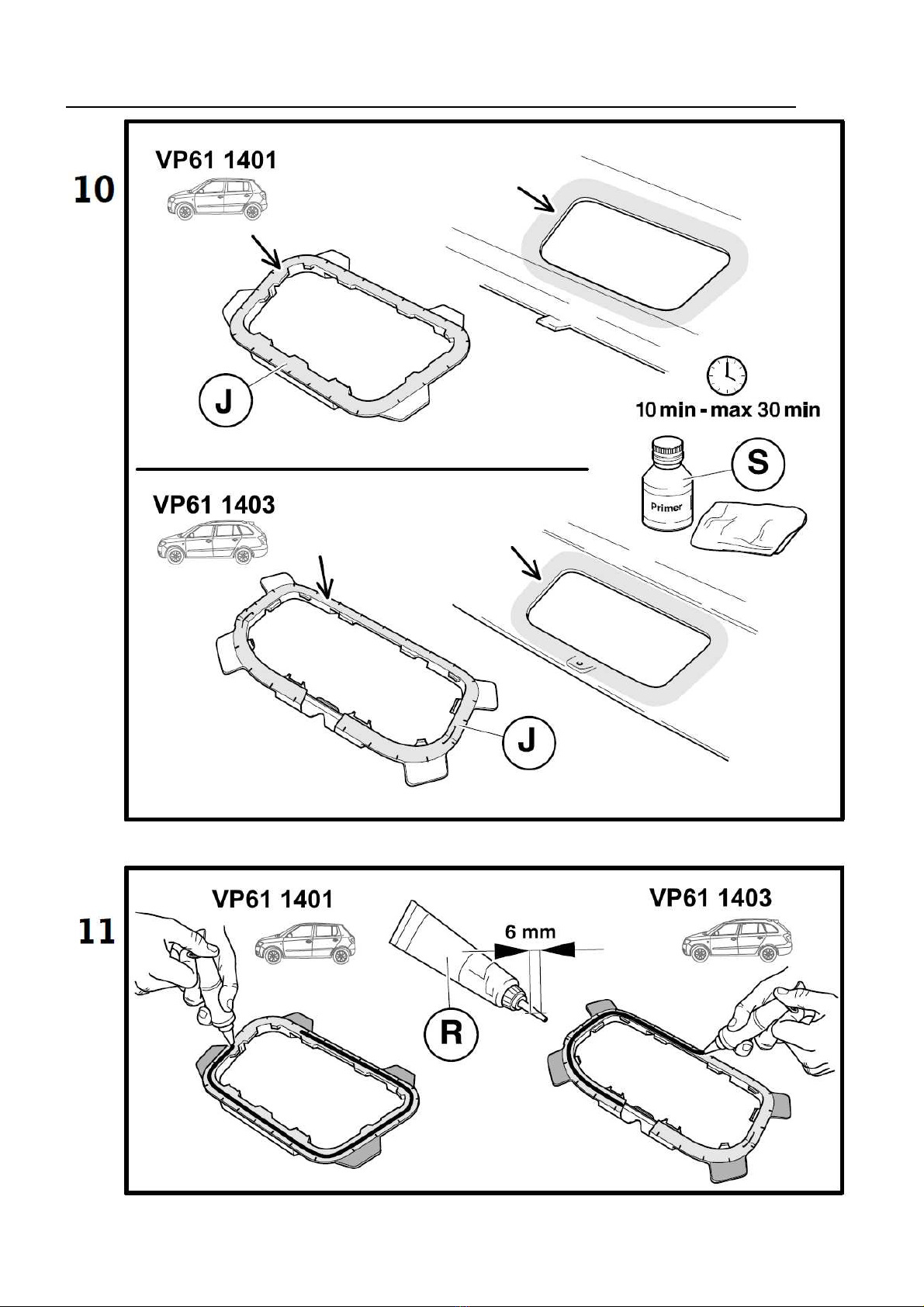
VP61 1401 cover with frame
For Škoda Fabia II Combi
VP61 1403 cover with frame
For vehicles of both types
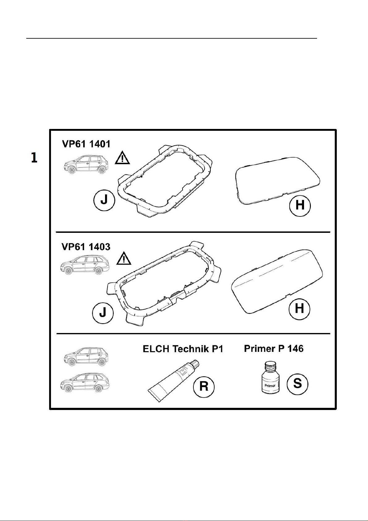
gluing seal ELCH Technik P1 80 ml (R)
activator Primer P146 (S)
For cutting the hole in the bumper, use the following set:
For Škoda Fabia II
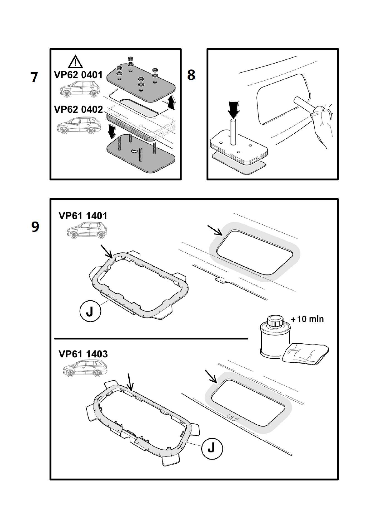
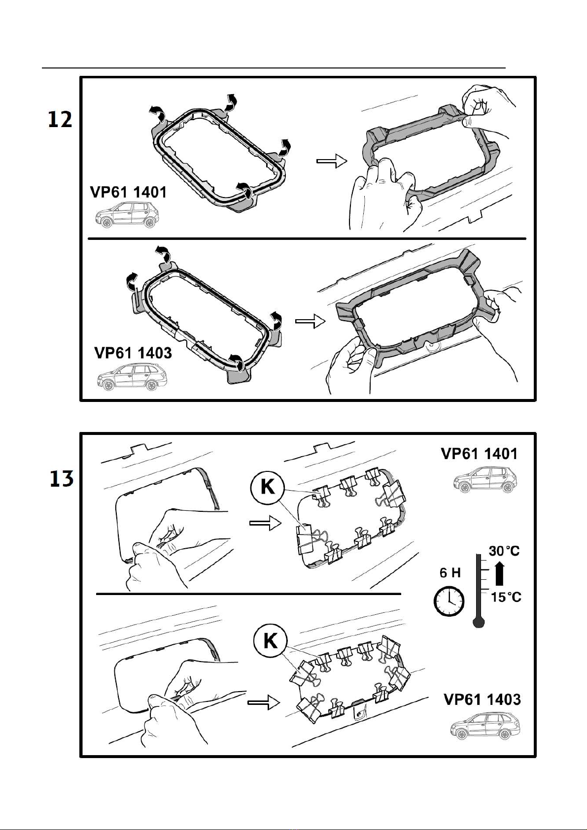
VP62 0401 punching tool for the cover of the rear bumper and clips (K) for fixing the frame
For Škoda Fabia II Combi
VP62 0402 punching tool for the cover of the rear bumper and clips (K) for fixing the frame

10
Set of cover (VP61 1401, VP61 1403) includes (fig. 1 – see instructions
for preparation of rear bumper Škoda Fabia II and Škoda Fabia II Combi – given below)
Name of part Pieces Position
Cover of hole of rear bumper 1 H
Frame for fastening the cover of hole of rear bumper 1 J
Punching tool (VP62 0401, VP62 0402) consists of following
parts (fig. 2 see instructions for preparation of rear bumper Škoda Fabia II and Škoda Fabia II Combi
– given below)
Name of part Pieces Position
Lower supporting board with four screws 1 L
Cutting board 1 M
Upper pressing board 1 N
Washer 10,5 4 O
NutM10 4 P
Clamp Fabia II 8 K
FabiaIICombi 9 K
(included in the set, not a part of the punching tool)
Fitting of the towing arm
1. Take the towing arm (1) out of the tool box in the luggage compartment.
2. Remove the cover of the hole in the rear bumper. Deposit the cover in a suitable place in the luggage
compartment of the vehicle (because of a possible damage to the snaps). Avoid damages to the paint
of the rear bumper and of the cover!
3. Take the cover (7) out of the hole of the clamping bush on the beam of the towing coupling pulling it
downwards and towards you at the same time and deposit it in a suitable place. Avoid a possible clash
of your hand with the edge of the hole in the bumper if removing it in a wrong way.
4. Check whether the towing arm is in the stand-by position. I.e. the safety pin (4) of the control lever
(3) is plugged in (its upper red section can be seen only) and the key is in unlocked position (its red
mark is visible).
5. If for some reason the towing arm is not in the stand-by position, proceed in the following way:
Unlock the lock (5) of the control lever (3) (turning the key through 180° to the left).
Grip the towing arm (1) below the ball journal with your left hand. Using the fingers of your right
hand, press down the safety pin (4) up to the stop, and at the same time, press down the control lever
up to the stop with your right hand. The control levers remains arrested in this position, and the towing
arm is ready for use.
6. Insert the towing arm (1) into the clamping bush (2) of the beam of the towing coupling as far as to the
upper clamping position. The clamping is accompanied by a sound (of the clamping balls being
snapped in the bushing), the control lever turns upwards and the safety pin is plugged out (its green
section is visible).

11
7. Turning the key (6) through 180° to the right, lock the lock of the control lever (its green mark is
visible) and take the key out. Check whether the towing arm is fitted properly. Try its fitting by
hand (shaking it vigorously).
8. Remove the cover (8) from the ball journal.
9. Fit a cap on the lock of the towing arm. Make sure the cap is fitted well.
Advice
-If the towing arm (1) is not in the stand-by position, it is not possible to clamp it into the clamping
bush (2) of the beam of the towing coupling.
-At fastening the towing arm have your hands outside the pathway of the clamping lever. Your
fingers could be injured at the backward movement of the lever into the clamping position!
-In case the towing arm is not correctly fixed in the clamping bush (i.e. the control lever is not in
the clamping position, so that the safety pin is not completely out, or the lock cannot be locked),
do not try to pull the control lever to its clamping position by force! Take the towing arm out,
check the cleanness of the wedge-shaped surfaces (both of the towing arm and of the clamping
bush) and then re-clamp the towing arm in the clamping bush.
-After fitting the towing arm, lock the lock always and take the key out. The towing arm may not
be operated with the key in the lock.
-In the stand-by position , it is not possible to take the key out of the lock of the control lever,
because of safety reasons.
-If you happen to lose the key, please contact the nearest service centre or the manufacturer
directly.
Removing of the towing arm
The towing arm is removed in the reversed way, according to the following instructions.
1. Remove the protecting cap of the towing arm lock, and turning the key (6) by 180° to the left, unlock
the lock of the control lever (its red mark can be seen).
2. Fit the cover (8) upon the ball journal.
3. Grip the towing arm from below with your left hand. Using the fingers of your right hand, press down
the safety pin (4) up to the stop, and at the same time, press down the control lever up to the stop with
your right hand. In this position, the towing arm is released, and will fall down to your left hand by
itself. At the same time, it gets locked in the stand-by position and therefore, it is ready for further
clamping into the clamping bush.
4. Wipe off dirt from the towing arm, and deposit it into the luggage compartment.
Caution! Never leave the towing arm lying freely in the luggage compartment. In case of sudden
braking, it could threaten the safety of the passengers and cause damage to the luggage
compartment.
Be careful to avoid damage to the paint of the bumper (or of the lower edge of the bumper hole)
when removing the towing arm.
5. Fit the cover (7) into the clamping bush of the beam of the towing coupling.
6. Clamp the cover into the hole of the rear buffer.

12
Advice
-The towing arm is to be deposited in the luggage compartment in the stand-by position, i.e. with
the key inserted in the lock. Caution: never lay the towing arm with the key inserted in the lock
downwards – the danger of damaging (bending) the key.
-Do not forget to fit the protecting cover into the clamping bush.
-When handling the towing arm, do press upon the control lever with more force than 600 N (60
kg)!
Operation and maintenance
-The towing coupling requires a minimum maintenance.
-When the towing arm has been removed, protect the hollow of the clamping bush (2) with the cover (7).
-Clean the hollow according to need, and apply a suitable preservation agent (e.g. WD 40).
-Warning! The upper part of the clamping bush cavityis treated with the AUTOL TOP 2000
lubricating grease,therefore take care that this grease is not removed. The clamping mechanism
of the towing arm must be kept clean.
-From time to time, lubricate the ball journal of the towing arm with a suitable lubricating grease.
-Meanwhile you are not using the towing arm, remove it and put it to its place in the luggage
compartment.
-When storing the towing arm, always use the protecting cover of the ball journal, in order to avoid
soiling of the luggage boot.
Important advice
-After having driven about the first 500 km with the trailer, it is necessary to check the tightening
of the screws clamping the beam to the chassis of the vehicle, and if necessary, to tighten them
with the prescribed torque 70 Nm! We recommend you to have it checked in the nearest service
centre.
-Any changes or alterations of the towing coupling are not admissible.
-Before every drive with the towing arm fitted, check the proper fitting of the towing arm and its
locking to the clamping bush of the beam of the towing coupling.
-The towing coupling must not be operated if the towing arm cannot be locked, or it is possible to
turn the control lever freely in the locked position.
-The towing coupling must not be operated if it is damaged or not complete.
-Never unlock the towing arm with a linked trailer.
-After linking the trailer and interconnecting the electric circuits, check the function of the lights
of the trailer.
-In case of a long-time operation with the towing arm fitted, in order to provide for the proper
functioning of the clamping mechanism it is necessary to clean it as needed, and to apply a
suitable preservation agent (e.g. WD 40 or a similar preserving agent) and to turn the lock of the
control lever several times.
-When handling the towing arm, do not press upon the control lever with more force than 600 N
(60 kg)!
When using the trailer coupling, follow the instructions given in the present Assembly Manual.
The manufacturer does not assume responsibility for any damages resulting from improper fitting
of the towing arm, its overloading or damage due to the car accidents.

13
Fitting of the towing coupling in the vehicle
1. Fix the vehicle upon the arms of a workshop jack.
2. Remove the rear bumper and the beam of the rear bumper.
Advice. After removing the beam of the rear bumper, add anticorrosive protection in the points of
contact between the bumper and the bodywork. The places without anticorrosive protection with
bare (zinc-coated) sheet metal are to be sprayed twice (min. 25 microns) with anticorrosive filler in
spray (Spray Max 1K Acryl Füller). Let the filler dry for about 20 min. at a temperature of about
20°C and apply preservation wax in spray.
3. Prepare the rear bumper:
Audi A1:
Select a diffuser with towing bracket opening and trim panel (towing bracket cover ) from the
electronic parts catalogue (ETKA) and replace it.
ŠKODA Fabia II and ŠKODA Fabia II Combi:
see instructions for preparation of rear bumper Škoda Fabia II and Škoda Fabia II Combi (given
below)
4. Remove the cappings from the holes for clamping the towing coupling on the rear longitudinal girders
(both sides of the vehicle). If necessary, remove parts of the plastic inside the longitudinal girders.
5. Fit the towing coupling by its longitudinal beams into the holes at the rear nose of the car and set it to
the correct position (see figure). By means of four screws M10 x 35 (B) fasten the beams to the chassis
of the vehicle. Pull the towing coupling backwards from the vehicle and tighten the screws
(alternately) on both sides with the tightening torque of 70 Nm.
6. Check the fitting of the towing arm (1) in the clamping bush of the beam of the towing coupling (see
the Fitting of the towing arm).
7. Fit the cover (7) into the clamping bush of the beam of towing coupling.
Next, proceed to the fitting of the electric installation of the towing coupling upon the vehicle (see
the instructions for fitting the electric installation of the towing coupling).
8. Having finished the fitting of the electric installation, fit all the removed parts back to their places and
tighten the respective connections at the prescribed torque moments.
9. After the fitting has been finished, affix the self-adhesive label 50 kg above the cutting in the rear
bumper (before affixing it, clean and degrease the place with the de-greaser).
The electric installation for the towing coupling is not included in the scope of the delivery, and it
must be ordered separately.

14
Guarantee information and conditions
The manufacturer of the towing coupling gives the guarantee for the construction, used material,
manufacturing execution and function of the supplied towing coupling for 24 months from the date of
sale.
The complaints are to be presented by the buyer to the selling organization within the legal period. The
rightfulness of the complaint will be judged by a representative of the selling organization together with a
representative of the manufacturer in accordance with valid regulations.
The prerequisite of validity of the guarantee is that the towing coupling has to be used only for those
purposes for which it is designed.
The buyer shall examine the condition of the goods at their reception. In case of any damage of the goods
or failure to deliver any part of the towing coupling the buyer shall report such fact immediately to the
selling organization without unnecessary delay after the reception of the goods.
All parts and accessories of the towing coupling must be checked before professional fitting with regard
to their compatibility with the respective type of vehicle. The towing couplings may be used only for the
vehicle type stated by the manufacturer. In case of incompetent fitting or fitting of the towing coupling on
a type of vehicle for which the towing coupling is not intended, the manufacturer shall not be responsible
for any damage of the towing coupling caused by defective fitting or its incorrect use.
The selling organization is responsible for defects the towing coupling had at its reception by the buyer.
The guarantee does not cover any damages resulting from common wear and tear, overloading and
unprofessional use, as well as damages caused by non-compliance with the instructions stated in the
operating manual. The guarantee does not cover any damages due to natural disasters. The selling
organization is not responsible for any damage in the case when the towing coupling was modified or
otherwise altered.
The guarantee also becomes void if the towing coupling has been damaged due to an
accident (except accidents caused by the towing coupling itself) or by tampering with its mechanism and
construction.
Compliance declaration
The producer of the towing equipment certifies hereby that it is produced according to the
approved documentation and complies with homologation e8*94/20*0064.
15
Anweisung für die Vorbereitung der Stoßfänger Škoda
Fabia II und Škoda Fabia II Combi
Instructions for preparation of rear bumper Škoda Fabia
II and Škoda Fabia II Combi

16

17
18
19
20
Table of contents
Languages:
Other PROF SVAR Automobile Accessories manuals


