PROF SVAR TMB PS 026 Instruction Manual

1
Škoda Roomster
Škoda Praktik
Uživatelský a montážní návod
Montage und Bedienungsanleitung
User’s guide and installation instructions
TMB PS 026
Tažné zařízení pro osobní vozidla
s odnímatelným tažným ramenem
Verbindungs-Anhängerkupplung für
Personenkraftwagen mit demontierbarem Kugelhals
Trailer coupling device for passenger cars with removable tow arm
e8 * 94/20 * 0054
© 15.3.2011

2

3
4

5
TAŽNÉ ZAŘÍZENÍ
Vážený zákazníku!
Tažné zařízení typ TMB PS 026 je určeno pro vozy Škoda Roomster, Škoda
Praktik. Očekáváme, že Vám bude co nejdéle sloužit k Vaší plné spokojenosti.
Před použitím tažného zařízení si pečlivěpřečtěte tuto uživatelskou příručku. Při
potížích s manipulací nebo závadách se obraťte na nejbližší autorizovaný servis,
kde Vám ochotněpomohou.
Technické parametry
Tažné zařízení je konstruováno pro připojení:
brzděného přívěsu do maximální hmotnosti 1200 kg
(platí údaj v technickém průkazu vozu)
nebrzděného přívěsu do max. hmotnosti 450 kg
(platí údaj v technickém průkazu vozu)
Průměr kulového čepu 50 mm
Max. svislé statické zatížení na kulový čep 50 kg
Dc - Wert (vztažná síla) 7,2 kN
C
T
CT
gDC
g - tíhové zrychlení (g = 9,81 ms-2)
T - max. hmotnost tažného vozidla [t]
C - max. hmotnost přívěsu [t]
Celková hmotnost tažného zařízení 14,5 kg
Rozměry 1015 x 590 x 205 mm

6
Montáž tažného ramena
Tažné rameno vyjměte z boxu na nářadí v zavazadlovém prostoru.
- 1 -
-Vyjměte krytku otvoru zadního nárazníku (H) -šipka- (pomocí háčku na
demontáž krytůkol - háček je součástí standartní výbavy vozu a je umístěn v
boxu na nářadí).
-Krytku uložte na vhodné místo do zavazadlového prostoru vozu (s ohledem na
možné poškození zácvaků). Pozor na poškození laku zadního nárazníku a
krytky!
- 2 -
-Vyjměte krytku (F) z otvoru upínacího pouzdra na nosníku tažného zařízení
zatažením směrem dolůa současněk sobě-šipka- a uložte ji na vhodné místo.
Pozor na možné střetnutí ruky a hrany otvoru nárazníku při nesprávném
vyjímání krytky.
- 3 -
-Zkontrolujte, je-li tažné rameno v pohotovostní poloze.
-Tzn. zajišťovací kolík ovladací páčky je zasunutý (je viditelná pouze jeho
vrchní červená část) a klíček je v odemknuté poloze (je viditelná jeho červená
značka)
-detail šipky-.
- 4 -
Není-li tažné rameno z nějakého důvodu v pohotovostní poloze postupujte
následujícím způsobem:
-Odemkněte zámek ovladací páčky (otočením klíčku o 180° doleva).
- Levou rukou uchopte tažné rameno pod kulovým čepem dle obrázku. Prsty
pravé ruky zamáčkněte zajišťovací kolík až na doraz a zároveňpravou rukou
stlačte dolůna doraz ovladací páčku. Ovladací páčka zůstane v této poloze
zaaretována a tažné rameno je připraveno k použití.
- 5 -
-Nasuňte tažné rameno (C) do upínacího pouzdra nosníku tažného zařízení až do
horní polohy upnutí.
-Toto upnutí je provázeno zvukem (zaskočením upínacích kuliček do pouzdra),
otočením ovladací páčky nahoru a vysunutím zajišťovacího kolíku (je viditelná
jeho zelená část) -detail šipka-.
-Sejměte krytku (D) z kulového čepu -šipka-.

7
- 6 -
-Otočením klíčku (E) o 180° vpravo uzamkněte zámek ovladací páčky (je
viditelná jeho zelená značka) a klíček vyjměte.
-Zkontrolujte, je-li tažné rameno správněnamontováno. Rukou (silným
zacloumáním) vyzkoušejte jeho upevnění.
- 7 -
-Na zámek tažného ramene nasaďte krytku. Ujistěte se, že je krytka dobře
nasazena.
Upozornění
-Pokud není tažné rameno v pohotovostní poloze, nelze jej upnout do
upínacího pouzdra nosníku tažného zařízení.
-Po nasazení tažného ramena vždy uzamkněte zámek a klíček vyjměte.
Tažné rameno nesmí být v provozu s klíčkem v zámku.
-Při upínání tažného ramena mějte ruce mimo dráhu upínací páčky. Při
zpětném pohybu páčky do upínací polohy může dojít ke zranění prstů!
-V případě, že není tažné rameno správněupnuté v upínacím pouzdře (tzn.
ovl. páčka není v upínací poloze a není tedy zcela vysunutý zajišťovací
kolík, nebo nelze uzamknout zámek), nesnažte se silou dotáhnout ovládací
páčku do své upínací polohy! Opětovněvyjměte tažné rameno,
překontrolujte čistotu klínových ploch (jak tažného ramena, tak upínacího
pouzdra) a potom tažné rameno znovu upněte v upínacím pouzdře.
-V pohotovostní poloze nelze z bezpečnostních důvodůvyjmout klíček ze
zámku ovládací páčky.
-Při ztrátěklíčku se obraťte na nejbližší autorizovaný servis nebo přímo na
výrobce.
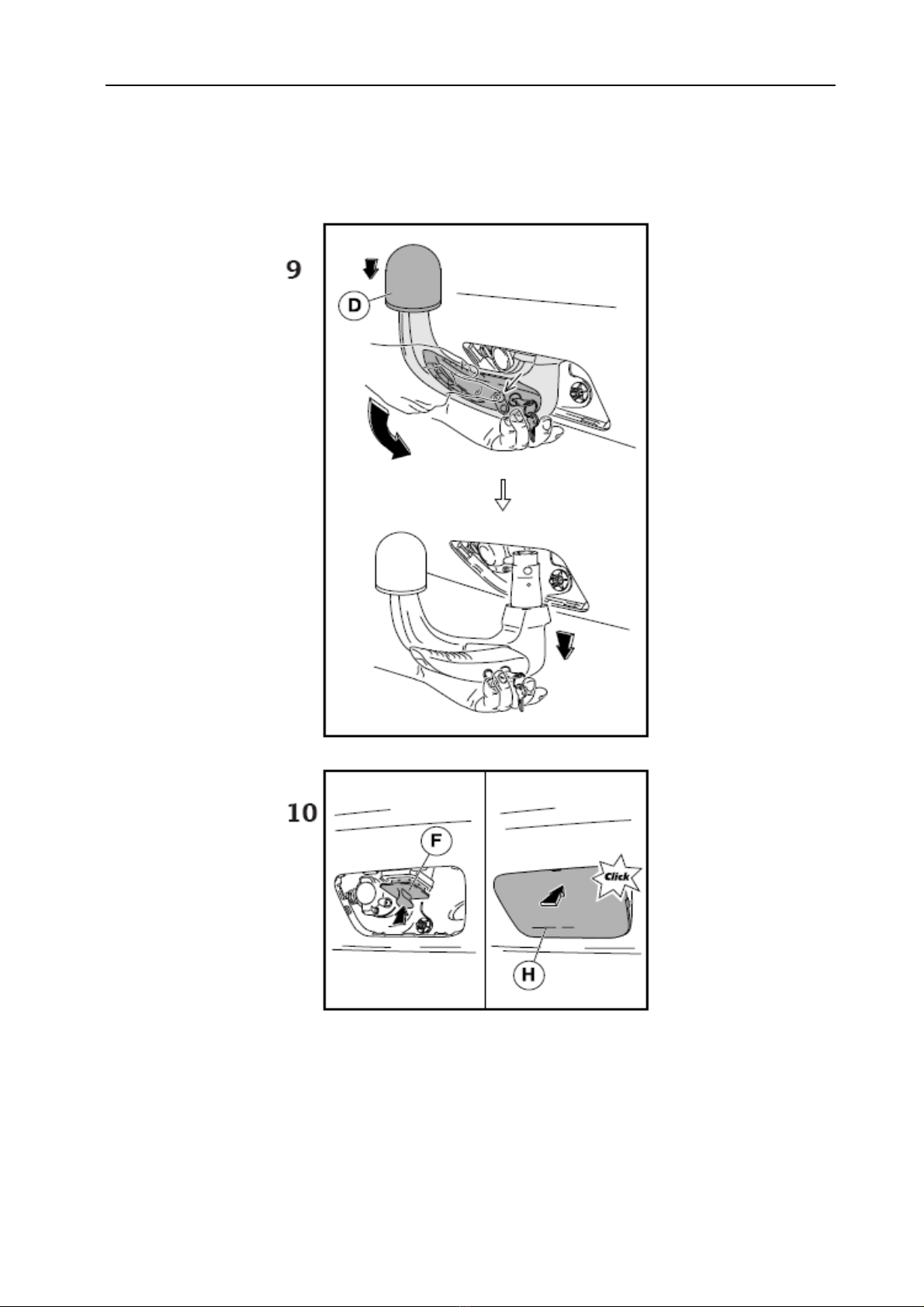
Demontáž tažného ramena
Demontáž tažného ramena proveďte opačným postupem dle následujících
pokynů.
- 8 -
-Sejměte ochranou krytku zámku tažného ramena a otočením klíčku (E) o 180°
vlevo odemkněte zámek ovladací páčky (je viditelná jeho červená značka).
- 9 -
-Nasaďte krytku (D) na kulový čep.
-Tažné rameno uchopte zespodu levou rukou. Prsty pravé ruky zamáčkněte
zajišťovací kolík až na doraz a zároveňpravou rukou stlačte dolůna doraz
ovladací páčku.

8
-V této poloze je tažné rameno uvolněno a volněvypadne do levé ruky dolů.
Zároveňse zajistí v pohotovostní poloze a je tak připraveno k dalšímu nasazení
do upínacího pouzdra.
-Otřete tažné rameno od nečistot a rameno uložte do zavazadlového prostoru.
Pozor! Tažné rameno nenechte nikdy ležet volněv zavazadlovém prostoru.
Při náhlém zabrzdění by mohlo ohrozit bezpečnost cestujících a způsobit
poškození zavazadlového prostoru.
Dbejte na to, aby při demontáži tažného ramene nedošlo k poškození laku
nárazníku (popř. spodní hrany otvoru v nárazníku).
- 10 -
-Krytku (F) nasaďte do upínacího pouzdra nosníku tažného zařízení.
-Nacvakněte krytku (H) do otvoru zadního nárazníku.
-Postup nasazení krytky: Nejdříve nasaďte krytku za „háčky“ na spodní
straněnárazníku. Potom zacvakněte levou a pravou stranu krytky a
nakonec zacvakněte horní stranu krytky.
Upozornění
-Tažné rameno ukládejte do zavazadlového prostoru v pohotovostní poloze,
tzn se zasunutým klíčkem v zámku. Pozor, nikdy nepokládejte tažné
rameno na stranu zasunutého klíčku v zámku - nebezpečí poškození
(ohnutí) klíčku.
-Nezapomeňte nasadit ochrannou krytku do upínacího pouzdra.
-Při manipulaci s tažným ramenem netlačte na ovladací páčku větší silou
než 600 N (60 kg)!
Provozování a údržba
-Tažné zařízení vyžaduje minimální údržbu.
-V případěvyjmutého tažného ramena chraňte dutinu upínacího pouzdra
krytkou.
-Dutinu dle potřeby vyčistěte a ošetřete vhodným konzervačním
přípravkem (např. WD 40).
-Pozor! Horní část dutiny upínacího pouzdra je ošetřenamazacím tukem
AUTOL TOP 2000, proto dbejte na to,aby tento tuk nebyl odstraněn.
Upínací mechanismus tažného ramena je nutné udržovat v čistotě.
-Kulový čep tažného ramena občas namažte vhodným mazacím tukem.
-Pokud tažné rameno nepoužíváte, demontujte jej a uložte na místo v
zavazadlovém prostoru.
-Při ukládání tažného ramena používejte vždy ochrannou krytku kulového čepu,
zabráníte tím znečištění zavazadlového prostoru.

9
Důležitá upozornění
-Po ujetí prvních asi 500 km s přívěsem nechte zkontrolovat dotažení
upínacích šroubůnosníku k podvozku vozidla a případnědotáhnout
předepsaným momentem 70 Nm! Tuto kontrolu Vám doporučujeme
provést v nejbližším autorizovaném servisu.
-Veškeré změny nebo úpravy tažného zařízení jsou nepřípustné.
-Před každou jízdou s nasazeným tažným ramenem zkontrolujte správné
nasazení tažného ramena a jeho uzamčení k upínacímu pouzdru nosníku
tažného zařízení.
-Tažné zařízení nesmí být provozováno, pokud tažné rameno nelze
uzamknout nebo v uzamčené poloze je možné ovladací páčkou volněotáčet.
-Tažné zařízení nesmí být provozováno, je-li poškozené nebo je neúplné.
-Tažné rameno nikdy neodjišťujte při připojeném přívěsu.
-Po připojení přívěsu a propojení elektrických obvodůzkontrolujte funkci
světel přívěsu.
-V případědlouhodobého provozu s nasazeným tažným ramenem je nutné
pro zabezpečení jeho správné funkce upínací mechanizmus dle potřeby
vyčistit a nakonzervovat vhodným přípravkem (např. WD 40 nebo
podobným konzervačním přípravkem) a několikrát otočit zámkem
ovladací páčky.
-Při manipulaci s tažným ramenem netlačte na ovladací páčku větší silou
než 600 N (60 kg)!
Při používání tažného zařízení dodržujte pokyny uvedené v tomto
uživatelském návodu.
Výrobce na sebe nebere zodpovědnost za škody způsobené chybně
namontovaným tažným ramenem, jeho přetěžováním nebo poškozením při
havárii vozidla.

10
ANHÄNGERKUPPLUNG
Werter Kunde!
Die Anhängerkupplung Typ TMB PS 026 ist für Fahrzeuge Škoda Roomster
und Škoda Praktik bestimmt. Wir erwarten, dass sie Ihnen lange zur vollen
Zufriedenheit dienen wird.
Lesen Sie vor dem Gebrauch der Anhängerkupplung das Benutzerhandbuch
aufmerksam durch. Sollten Schwierigkeiten bei der Handhabung oder Fehler
auftreten, wenden Sie sich bitte an Ihren nächsten-Betrieb, wo Ihnen gern
geholfen wird.
Technische Angaben
Die Anhängerkupplung ist konstruiert zum Anschluss:
des gebremsten Anhängers zum Höchstgewicht 1200 kg
(es gilt die Angabe im Fahrzeugbrief)
des nicht gebremsten Anhängers zum Höchstgewich 450 kg
(es gilt die Angabe im Fahrzeugbrief)
Kugelbolzen-Durchmesser 50 mm
Maximale vertikale statische Last auf den Kugelbolzen 50 kg
Dc - Wert (Bezugskraft) 7,2 kN
C
T
CT
gDC
g - Fallbeschleunigung (g = 9,81 ms-2)
T – Höchstgewicht des Schleppfahrzeuges [t]
C - Höchstgewicht des Anhängers [t]
Gesamtgewicht der Anhängerkupplung 14,5 kg
Maβe 1015 x 590 x 205 mm

11
Schlepparm einbauen
Nehmen Sie den Schlepparm aus der Werkzeugbox im Kofferraum heraus.
- 1 -
-Nehmen Sie die Abdeckung für die Öffnung des Stoβfängers hinten (H) -Pfeil-
heraus (mit Haken zum Radkappen- ausbau – Haken ist Bestandteil der
Standardausstattung des Fahrzeuges und befindet sich in der Werkzeugbox).
-Verstauen Sie die Abdeckung auf einen geeigneten Platz im Kofferraum (mit
Rücksicht auf mögliche Beschädigung der Verrastungen). Vorsicht auf
Lackbeschädigung des Stoβfängers und der Abdeckungen!
- 2 -
-Nehmen Sie die Abdeckung (F) aus der Öffnung der Spannhülse am
Anhängerkupplungsträger durch Ziehen nach unten und gleichzeitig zu sich -
Pfeil-
-ab und verstauen Sie sie auf einen geeigneten Platz. Vorsicht auf möglichen
Zusammenstoβder Hand und der Öffnungskante des Stoβfängers bei
Fehlentnahme der Abdeckung.
- 3 -
-Prüfen Sie, ob der Schlepparm in Bereitschaftslage steht.
-D. h., der Sicherungsstift des Betätigungshebels ist eingesteckt (nur sein rotes
Oberteil ist sichtbar) und der Schlüssel ist in der entriegelten Lage (seine rote
Markierung ist sichtbar) -Pfeildetail-.
- 4 -
Steht der Schlepparm aus irgendwelchem Grund nicht in Bereitschaftslage,
verfahren Sie folgendermaβen:
- entriegeln Sie das Schloss des Betätigungshebels (durch Linksdrehen des
Schlüssels um 180º).
- fassen Sie den Schlepparm unterhalb des Kugelbolzens mit der Hand wie in der
Abb. gezeigt an. Drücken Sie den Sicherungsstift mit Fingern der rechten Hand
bis zum Anschlag ein und drücken Sie gleichzeitig mit der rechten Hand den
Betätigungshebel bis zum Anschlag nach unten. Der Betätigungshebel bleibt in
dieser Lage arretiert und der Schlepparm ist zum Gebrauch vorbereitet.
- 5 -
-Setzen Sie den Schlepparm (C) in die Spannhülse des
Anhängerkupplungsträgers bis in die obere Lage der Spannung ein.
-Diese Spannung wird mit einem Ton begleitet (durch Einrasten der
Aufnahmekugeln in die Hülse), durch Drehen des Betätigungshebels nach oben

12
und Ausschieben des Sicherungsstiftes (sein grünes Teil ist sichtbar) -Detail
Pfeil-.
-Nehmen Sie die Abdeckung (D) vom Kugelbolzen -Pfeil- ab.
- 6 -
-Durch Rechtsdrehen des Schlüssels (E) um 180º verriegeln Sie das Schloss des
Betätigungshebels (seine grüne Markierung ist sichtbar) und ziehen Sie den
Schlüssel ab. Prüfen Sie, ob der Schlepparm richtig eingebaut ist. Prüfen
Sie von Hand (durch kräftiges Herumzerren) seine Befestigung.
- 7 -
-Auf das Kugelstangenschloss die Kappe aufsetzen. Richtigen Sitz der Kappe
beachten.
Hinweis
-Wenn der Schlepparm nicht in Bereitschaftslage steht, kann er nicht in die
Spannhülse des Anhängerkupplungsträgers eingespannt werden.
-Nach dem Einsetzen des Schlepparms verschlieβen Sie immer das Schloss
und ziehen Sie den Schlüssel ab. Der Schlepparm darf mit dem Schlüssel
im Schloss nicht im Betrieb sein.
-Haben Sie die Hände beim Einspannen des Schlepparmes außerhalb der
Klemmhebelspur. Beim Rückzug des Hebels in die Einspannstelle können
die Finger verletzt werden!
-Falls der Schlepparm nicht richtig in der Spannhülse eingespannt ist (d. h.
der Betätigungshebel steht nicht in der Einspannstelle und der
Sicherungsstift ist also nicht völlig herausgeschoben, oder das Schloss geht
nicht verriegeln), bemühen Sie sich nicht den Betätigungshebel in seine
Einspannstelle mit Gewalt festzuziehen! Nehmen Sie den Schlepparm
wiederholt heraus, überprüfen Sie die Sauberkeit der Keilflächen (sowohl
vom Schlepparm, als auch von der Spannhülse) und spannen Sie
anschließend den Schlepparm wiederholt in der Spannhülse ein.
-In Bereitschaftslage kann der Schlüssel aus dem Schloss des
Betätigungshebels nicht abgezogen werden.
-Wenn der Schlüssel verloren geht, wenden Sie sich an den nächsten-
Betrieb oder direkt an den Hersteller.

13
Schlepparm ausbauen
Den Ausbau des Schlepparms führen Sie in der umgekerten Reihenfolge durch
gemäβfolgenden Hinweisen.
- 8 -
-Schutzkappe für das Kugelstangenschloss abnehmen und das Schloss des
Betätigungshebels durch eine 180°-Linksdrehung des Schlüssels (E)
aufschließen (rote Markierung am Schloss ist sichtbar).
- 9 -
-Setzen Sie die Abdeckung (D) auf den Kugelbolzen auf.
-Fassen Sie den Schlepparm von unten mit der linken Hand an. Drücken Sie den
Sicherungsstift mit Fingern der rechten Hand bis zum Anschlag ein und
drücken Sie gleichzeitig mit der rechten Hand den Betätigungshebel bis zum
Anschlag nach unten.
-In dieser Lage ist der Schlepparm gelöst und fällt frei nach unten in die linke
Hand heraus. Er wird gleichzeitig in der Bereitschaftslage gesichert und ist so
zum nächsten Einsetzen in die Spannhülse vorbereitet.
-Wischen Sie den Schlepparm von Schmutz ab und verstauen Sie den Arm im
Kofferraum.
Achtung! Lassen Sie den Schlepparm niemals frei im Kofferraum liegen. Bei
plötzlichen Bremsmanövern könnte er die Sicherheit der Fahrgäste
bedrohen und den Kofferraum beschädigen.
Achten Sie darauf, dass beim Ausbau des Schlepparmes keine
Lackbeschädigung des Stoßfängers (bzw. Der Öffnung-Unterkante im
Stoßfänger) vorkommt.
- 10 -
-Setzen Sie die Abdeckung (F) in die Spannhülse des Anhängerkupplungsträgers
ein.
-Rasten Sie die Abdeckung (H) in die Öffnung des Stoβfängers hinten ein.
-Einsatzreihenfolge der Abdeckung: Setzen Sie die Abdeckung zuerst mit
„Haken“ an der Stoβfänger-Unterseite ein. Rasten Sie dann die linke und
rechte Seite der Abdeckung und anschlieβend die Oberseite der
Abdeckung ein.

14
Hinweise
-Verstauen Sie den Schlepparm in Bereitschaftslage im Kofferraum, d. h.
mit im Schloss eingestecktem Schlüssel. Vorsicht, legen Sie den
Schlepparm niemals auf die Seite mit im Schloss eingestecktem Schlüssel –
Schlüssel- Beschädigungsgefahr (Schlüsselverbiegung).
-Vergessen Sie nicht die Schutzkappe in die Spannhülse einzusetzen.
-Bei Handhabung mit Schlepparm drücken Sie den Betätigungshebel nicht
mit mehr Kraft als 600 N (60 kg).
Betrieb und Wartung
-Die Anhängerkupplung erfordert minimale Wartung.
-Wenn sie abgenommen wird, schützen Sie den Hohlraum der Spannhülse mit
der Kappe.
-Säubern Sie und behandeln Sie den Hohlraum entsprechend dem Bedarf
mit geeignetem Konservierungsmittel (z. B. WD 40).
-Vorsicht! Der Hohlraum-Oberteil der Spannhülse istmit Schmierfett
AUTOL TOP 2000 behandelt, achten Siedeshalb darauf, dass dieses Fett
nicht entfernt wird. DieKlemmeinrichtung des Schlepparms muss sauber
gehalten werden.
-Fetten Sie ab und zu den Kugelbolzen des Schlepparms mit geeignetem
Schmierfett.
-Wenn Sie den Schlepparm nicht benutzen, bauen Sie ihn aus und verstauen Sie
ihn im Kofferraum.
-Verwenden Sie beim Verstauen des Schlepparms immer die Schutzkappe für
Kugelbolzen, Sie vermeiden damit die Verunreinigung des Kofferraums.

15
Wichtige Hinweise
-Wenn Sie die ersten ca. 500 km mit Anhänger zurück- gelegt haben, lassen
Sie das Festziehen der Befestigungsschrauben Träger an Fahrwerk des
Fahrzeuges überprüfen und ggf. mit vorgeschriebenem Anzugs-
drehmoment 70 Nm festziehen. Wir empfehlen Ihnen, diese Prüfung im
nächsten-Betrieb durchführen zu lassen.
-Alle Veränderungen bzw. Bearbeitungen an der Anhängerkupplung sind
nicht zulässig.
-Überprüfen Sie vor jeder Fahrt mit eingesetzem Schlepparm das
ordnungsgemäβe Einsetzen des Schlepparms und die Verriegelung an
Spannhülse des Anhängerkupplungsträgers.
-Die Anhängerkupplung darf nicht in Betrieb gesetzt werden, wenn der
Schlepparm nicht verriegelt werden kann oder der Betätigungshebel in der
verriegelten Lage sich frei drehen lässt.
-Die Anhängerkupplung darf nicht in Betrieb gesetzt werden, wenn sie
beschädigt bzw. nicht komplett ist.
-Entriegeln Sie den Schlepparm niemals bei angekuppeltem Anhänger.
-Wenn der Anhänger angekuppelt und der Schaltkreis verbunden ist,
prüfen Sie die Anhängerleuchten auf Funktion.
-Bei Dauerbetrieb mit eingesetzem Schlepparm muss die Klemmeinrichtung
entsprechend dem Bedarf gereingt und mit geeignetem
Konservierungsmittel (z. B. WD 40 bzw. mit ähnlichem
Konservierungsmittel) konserviert und mehrmals mit dem Schloss des
Betätigungshebels gedreht werden, damit die richtige Funktion gesichert
ist.
-Bei Handhabung mit Schlepparm drücken Sie den Betätigungshebel nicht
mit mehr Kraft als 600 N (60 kg).
Bei Verwendung der Anhängerkupplung beachten Sie die in dieser
Montageanleitung angeführten Hinweise.
Der Hersteller übernimmt keine Verantwortung für Schäden verursacht
durch falsch eingebauten Schlepparm, Überlastung oder Beschädigung bei
Vekehrsunfall.

16
TOWING COUPLING
Dear Customer!
The towing coupling type TMB PS 026 is designed for the vehicles Škoda
Roomster and Škoda Praktik. We expect it will serve you to your full satisfaction
as long as possible.
Please read this User Manual carefully prior to using the towing coupling. In case
of problems with handling it, or if any defect should occur, contact the nearest
Service Centre, where they are ready to assist you.
Technical parameters
The towing coupling has been designed for linking with:
A trailer with brakes, up to maximum weight 1200 kg
(consult the Technical Certificate of the car)
A trailer without brakes, up to maximum weight 450 kg
(consult the Technical Certificate of the car)
Diameter of the ball journal 50 mm
Max. vertical static load upon the ball journal 50 kg
Dc - Wert (relative strength) 7,2 kN
C
T
CT
gDC
g – gravity acceleration (g = 9,81 ms-2)
T – max. weight of the trailing vehicle [t]
C – max. weight of the trailer [t]
The total weight of the towing coupling 14,5 kg
Dimensions 1015 x 590 x 205 mm

17
Fitting of the towing arm
Take the towing arm out of the tool box in the luggage compartment.
- 1 -
-Remove the cover of the hole in the rear bumper (H) -arrow- (by means of the
hook for removing wheel caps – the hook is a part of the standard equipment of
the vehicle and it is placed in the tool box).
-Deposit the cover in a suitable place in the luggage compartment of the vehicle
(because of a possible damage to the snaps). Avoid damages to the paint of
the rear bumper and of the cover!
- 2 -
-Take the cover (F) out of the hole of the clamping bush on the beam of the
towing coupling pulling it downwards and towards you at the same time -
arrow- and deposit it in a suitable place. Avoid a possible clash of your hand
with the edge of the hole in the bumper if removing it in a wrong way.
- 3 -
-Check whether the towing arm is in the stand-by position.
-I.e. the safety pin of the control lever is plugged in (its upper red section can be
seen only) and the key is in unlocked position (its red mark is visible) -detail
arrows-.
- 4 -
If for some reason the towing arm is not in the stand-by position, proceed in
the following way:
- Unlock the lock of the control lever (turning the key through 180° to the left).
- Grip the towing arm below the ball journal with your left hand according to the
figure. Using the fingers of your right hand, press down the safety pin up to the
stop, and at the same time, press down the control lever up to the stop with your
right hand. The control levers remains arrested in this position, and the towing
arm is ready for use.
- 5 -
-Insert the towing arm (C) into the clamping bush of the beam of the towing
coupling as far as to the upper clamping position.
-The clamping is accompanied by a sound (of the clamping balls being snapped
in the bushing); the control lever turns upwards and the safety pin is plugged
out (its green section is visible) -detail arrow-.
-Remove the cover (D) from the ball journal -arrow-.
- 6 -
-Turning the key (E) through 180° to the right, lock the lock of the control lever
(its green mark is visible) and take the key out.

18
Check whether the towing arm is fitted properly. Try its fitting by hand
(shaking it vigorously).
- 7 -
-Fit a cap on the lock of the towing arm. Make sure the cap is fitted well.
Advice
-If the towing arm is not in the stand-by position, it is not possible to clamp
it into the clamping bush of the beam of the towing coupling.
-At fastening the towing arm have your hands outside the pathway of the
clamping lever. Your fingers could be injured at the backward movement
of the lever into the clamping position!
-In case the towing arm is not correctly fixed in the clamping bush (i.e. the
control lever is not in the clamping position, so that the locking peg is not
completely out, or the lock cannot be locked), do not try to pull the control
lever to its clamping position by force! Take the towing arm out, check the
cleanness of the wedge-shaped surfaces (both of the towing arm and of the
clamping bush) and then re-clamp the towing arm in the clamping bush.
-After fitting the towing arm, lock the lock always and take the key out. The
towing arm may not be operated with the key in the lock.
-In the stand-by position , it is not possible to take the key out of the lock of
the control lever, because of safety reasons.
-If you happen to lose the key, please contact the nearest service centre or
the manufacturer directly.
Removing of the towing arm
The towing arm is removed in the reversed way, according to the following
instructions.
- 8 -
-Remove the protecting cap of the towing arm lock, and turning the key (E) by
180° to the left, unlock the lock of the control lever (its red mark can be seen).
- 9 -
-Fit the cover (D) upon the ball journal.
-Grip the towing arm from below with your left hand. Using the fingers of your
right hand, press down the safety pin up to the stop, and at the same time, press
down the control lever up to the stop with your right hand.

19
-In this position, the towing arm is released, and will fall down to your left hand
by itself. At the same time, it gets locked in the stand-by position and therefore,
it is ready for further clamping into the clamping bush.
-Wipe off dirt from the towing arm, and deposit it into the luggage compartment.
Caution! Never leave the towing arm lying freely in the luggage
compartment. In case of sudden braking, it could threaten the safety of the
passengers and cause damage to the luggage compartment.
Be careful to avoid damage to the paint of the bumper (or of the lower edge
of the bumper hole) when removing the towing arm.
- 10 -
-Fit the cover (F) into the clamping bush of the beam of the towing coupling.
-Clamp the cover (H) into the hole of the rear buffer.
-Procedure of fitting the cover: First, engage the cover with the „hooks“ on
the bottom side of the buffer. Next, clamp the L.H. and the R.H. sides of
the cover, and finally, clamp the upper side of the cover.
Advice
-The towing arm is to be deposited in the luggage compartment in the
stand-by position, i.e. with the key inserted in the lock. Caution: never lay
the towing arm with the key inserted in the lock downwards – the danger
of damaging (bending) the key.
-Do not forget to fit the protecting cover into the clamping bush.
-When handling the towing arm, do press upon the control lever with more
force than 600 N (60 kg)!
Operation and maintenance
-The towing coupling requires a minimum maintenance.
-When the towing arm has been removed, protect the hollow of the clamping
bush with the cover.
-Clean the hollow according to need, and apply a suitable preservation
agent (e.g. WD 40).
-Warning! The upper part of the clamping bush cavityis treated with the
AUTOL TOP 2000 lubricating grease,therefore take care that this grease is
not removed. The clamping mechanism of the towing arm must be kept
clean.

20
-From time to time, lubricate the ball journal of the towing arm with a suitable
lubricating grease.
-Meanwhile you are not using the towing arm, remove it and put it to its place in
the luggage compartment.
-When storing the towing arm, always use the protecting cover of the ball
journal, in order to avoid soiling of the luggage boot.
Important advice
-After having driven about the first 500 km with the trailer, it is necessary
to check the tightening of the screws clamping the beam to the chassis of
the vehicle, and if necessary, to tighten them with the prescribed torque 70
Nm! We recommend you to have it checked in the nearest service centre.
-Any changes or alterations of the towing coupling are not admissible.
-Before every drive with the towing arm fitted, check the proper fitting of
the towing arm and its locking to the clamping bush of the beam of the
towing coupling.
-The towing coupling must not be operated if the towing arm cannot be
locked, or it is possible to turn the control lever freely in the locked
position.
-The towing coupling must not be operated if it is damaged or not complete.
-Never unlock the towing arm with a linked trailer.
-After linking the trailer and interconnecting the electric circuits, check the
function of the lights of the trailer.
-In case of a long-time operation with the towing arm fitted, in order to
provide for the proper functioning of the clamping mechanism it is
necessary to clean it as needed, and to apply a suitable preservation agent
(e.g. WD 40 or a similar preserving agent) and to turn the lock of the
control lever several times.
-When handling the towing arm, do not press upon the control lever with
more force than 600 N (60 kg)!
When using the trailer coupling, follow the instructions given in the present
Assembly Manual.
The manufacturer does not assume responsibility for any damages resulting
from improper fitting of the towing arm, its overloading or damage due to
the car accidents.
Table of contents
Languages:
Other PROF SVAR Automobile Accessories manuals


