CLIMATE
&
CONVENIENCE
CONTROLS
(Lett screen cont'd)
TEMPERATURE CONTROL (Page 10 Fig. 3, #8-10)
Use the UP and DOWN arrows (Page 10 Fig. 3, #8
&
#1
0) on the color
TFT
touch screen to adjust vehicle
air
temperature. Touch the Red <Up> arrow to increase airtemp. Touch the Blue <Down> arrow to
decrease air temp.The temperature indicatorwi
ll
move up
or
down indicating the current temperature level.
The temperature range is color-coded: Red indicates warmer
air
and Blue indicates coolerair.
CLIMATE
&
CONVENIENCE
CONTROLS
(RightScreen)
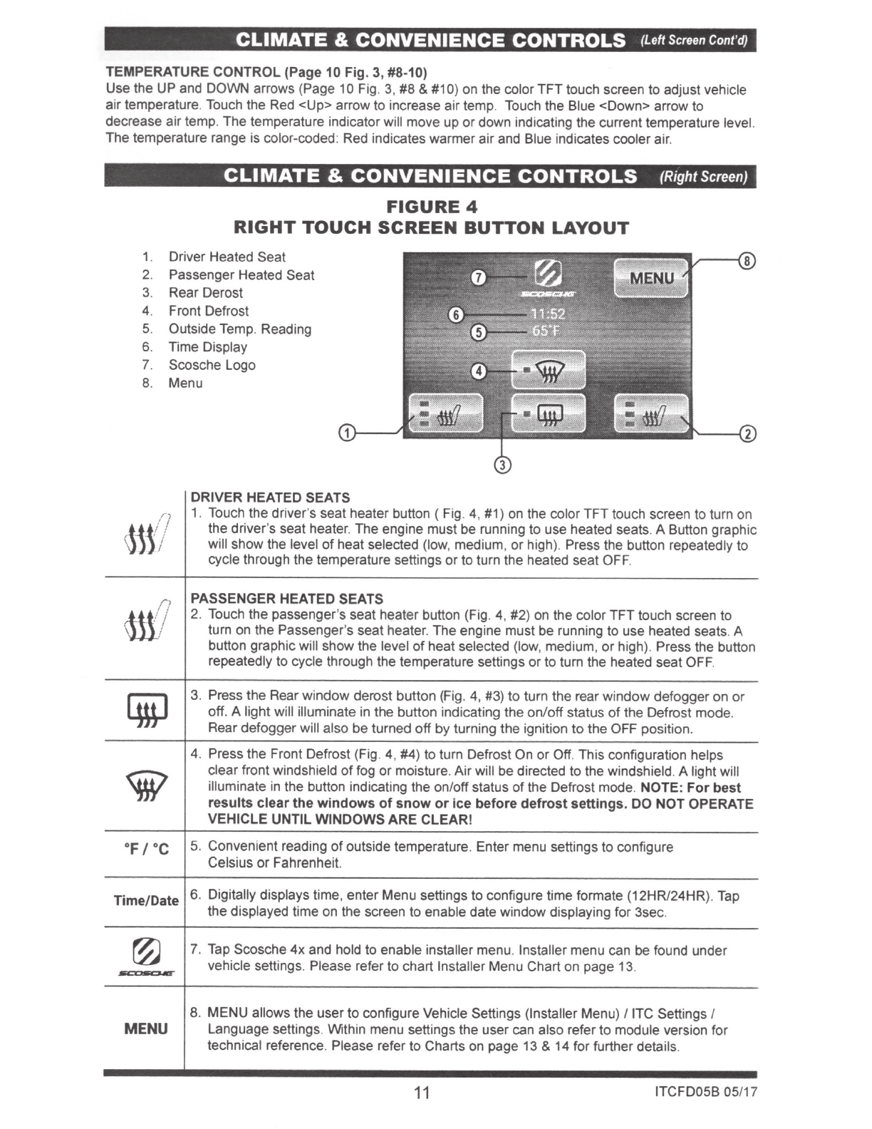
FIGURE
4
RIGHT
TOUCH
SCREEN
BUTTON
LAYOUT
1. Driver Heated Seat
2. Passenger Heated Seat
3. Rear Derost
4.
Front Defrost
5. Outside Temp. Reading
6. Time Display
7. Scosche Logo
8. Menu
DRIVER HEATED SEATS
/)
1. Touch the driver's seat heater button ( Fig. 4, #1)
on
the color TFTtouch screen to turn on
1~t
/
the driver's seat heater. The engine must be running to use heated seats.A Button graphic
will show the level
of
heat selected (low, medium,
or
high). Press the button repeatedly
to
cycle through the temperature settings
or
to turn the heated seat OFF.
~
PASSENGER HEATED SEATS
I
2. Touch the passenger's seat heater button (Fig. 4, #2) on the color TFT touch screen to
I
tum on the Passenger's seat heater. The engine must be running
to
use heated seats.A
button graphicwill show the level
of
heat selected (low, medium,
or
high). Press the button
repeatedly to cycle through the temperature settings or to turn the heated seat
OFF.
[iJ
3. Press the Rear window derost button (Fig. 4, #3)
to
turn the rear window defoggeron
or
off
. A light will illuminate in the button indicating the on/off status
of
the Defrost mode.
Reardefogger will also be turned
off
by
turning the ignition
to
the OFF position.
4. Press the Front Defrost (Fig. 4, #4) to turn Defrost On or Off. This configuration helps
~
clearfront windshield
of
fog
or
moisture.Airwill be directed to the windshield.A light will
illuminate in the button indicating the on/offstatus
of
the Defrost mode. NOTE:
For
best
results
clear
the
windows
of
snow
or
ice
before
defrost
settings
. DO NOT OPERATE
VEHICLE UNTIL WINDOWS ARE CLEAR!
OF
I
oc
5. Convenient reading
of
outside temperature. Enter menu settings
to
configure
Celsius
or
Fahrenheit.
Time/Date 6. Digitally displays time, enter Menu settings to configure time formate (12HRI24HR).
Tap
the displayed time on the screen to enable date window displaying for 3sec.
@
7. Tap Scosche
4x
and hold
to
enable installer menu. Installer menu can be found under
~
vehicle settings. Please refer to chart Installer Menu Chart on page 13.
8. MENU allows the user
to
configure Vehicle Settings (Installer Menu)
/lTC
Settings I
MENU
Language settings. Within menu settings the user can also refer
to
module version for
technical reference. Please refer to Charts on page 13 & 14 for further details.
11
ITCFD05B 05/17