proFEX MG-200 User manual

Gradiometer MG-200

Table of Contents
Part 1. Introduction
1.1 Basic technical specifications of gradiometer MG 200
1.2 Accessories included
1.3 How gradiometer works
Part 2. Batteries and Charging
Part 3. Gradiometer design and operation
3.1 Design and keyboard
3.2 Display mode “MENU”
3.3 Display mode “OPERATION”
3.4 Field work and search with gradiometer
Part 4. Gradiometer tuning
4.1 Balancing
4.2 Alignment
Part 5. Frequently asked questions
Precautions
Warranty

Part 1. Introduction
Flux gate gradiometer MG-200 is a search device designed for rapid locating of magnetized objects
underneath layer of soil, water, ice, and asphalt on depths varying form several inches to several meters.
The most typical search objects are meteorites that contain iron, military artifacts of past wars, as well
as any other objects containing iron, including pipes, lost and covered potholes, oil containers, cables,
and unexploded ordnance.
Sound and visual indication of MG-200 can be customized by the user to search for specific targets,
which in combination with light weight (5.5 lbs.) and compact design, allows for effective search and
high accessibility on difficult terrain (desert, forest, mountains, swamps, etc.)
1.1 Basic technical specifications of gradiometer MG 200
Sensitivity: 0.4 nT/m (0.1 units)
Frequency of measurements: 10 times per second
Frequency of information display: 10 times per second
Gradient resistivity: 80,000 nT/m (20,000 units)
Battery capacity: 50 hours with battery capacity no less than 2500 mAh and temperature 68 F
Temperature range: 14-122 F
Power consumption: 100mA +/- 10%
Weight: 5.5 lbs.
1.2 Accessories included
Gradiometer MG-200
Rechargeable batteries –8 pcs
AC charger
Car charger
Owner’s manual
Bag

1.3 How gradiometer works
Gradiometer is a device that measures gradient of magnetic field or difference in magnetic field levels
between two points in space. Since magnetic field of any magnetized object weakens as the distance to
the object increases, it will have a gradient. Absence of magnetized object means absence of magnetic
field and therefore gradient equals 0.
Measurements of magnetic field are taken at two different points in space, where gradiometer sensors
are located –upper and lower. Difference between the measurements is called gradient and is digitally
displayed on the screen.
Magnetic field is measured in special units –“Tesla”. 1/100,000 Tesla is called “nanotesla”. Gradient
depends on the distance between measurement points and so the difference in measurements is tied to
the distance between them and is measured in “nanotesla over meter” – nT/m. Gradiometer MG-200
measures magnetic field in units which equal 4 nT. In order to translate the result into nT, simply
multiply the number on display by 4.
In order for gradiometer to correctly measure the gradient, its sensors must be identical in sensitivity
and precisely aligned. But sensors are susceptible to environment and first of all –changes in
temperature. As time passes changes in temperature cause mechanical and electrical changes in
sensors. These changes are miniscule but may result in increased interferences when gradiometer is
tilted during movement (sensors not balanced) or when making directional turns (sensors not aligned).
In this case sensors require tuning.
There are only two types of tuning: if interferences arise from tilting gradiometer while walking, sensor
sensitivity needs to be balanced; if interferences arise on turns (changing the direction of movement),
sensors’alignment needs to be tuned. Both types of tuning are simple, can be performed as needed and
after a little practice take only a couple minutes.
Need for tuning is decided by the user depending on the level of interference that he deems acceptable
for specific type of search.

Part 2. Batteries and Charging
Gradiometer includes 8 standard rechargeable batteries –AA type with 2500 mAh capacity each. They
allow the device to operate for 50 hours. If only 4 similar batteries are installed the device will work for
25 hours. Time necessary for complete recharging of batteries is 4-6 hours. Regular, non-rechargeable
AA batteries can be used as well. Time of operation will be between 15 and 60 hours depending on the
manufacturer of batteries.
CAUTION! NEVER RECHARGE NON-RECHARGEABLE BATTERIES!
Need for charging is indicated by the blinking symbol ≤≤≤ in the upper right corner of the display.
Charging is done by connecting the AC or car charger to the plug on the battery compartment of the
device. Both types of adapter are included with the device.
To charge gradiometer –turn it off and plug the appropriate adapter into the battery compartment.
The device will test the level of the battery charge and display it on the screen in %. After batteries are
fully charged the device will play a sound and stop charging. The sound will continue to play every 3
minutes.
Replacing batteries. Remove 4 screws on the battery compartment, remove the batteries, and install
new ones. CAUTION! ALWAYS INSTALL SIMILAR TYPE BATTERIES FROM THE SAME BATCH! OTHERWISE
THEIR SAFETY AND LIFE OF OPERATION ARE NOT GUARANTEED!
Non-rechargeable AA batteries can be used as well. If batteries of a different capacity than the ones
used by the manufacturer are installed, level of charge indicated by the device may not be precise.
Since all batteries are magnetic, after replacing them, check balancing and alignment tuning of the
sensors.
Part 3. Gradiometer design and operation
This part of the manual will introduce the user to the basic modes of magnetometer operation,
keyboard functions, as well as give practical advice on how to conduct effective field search and tune
the device.
3.1 Design and keyboard.
4
2
1
3
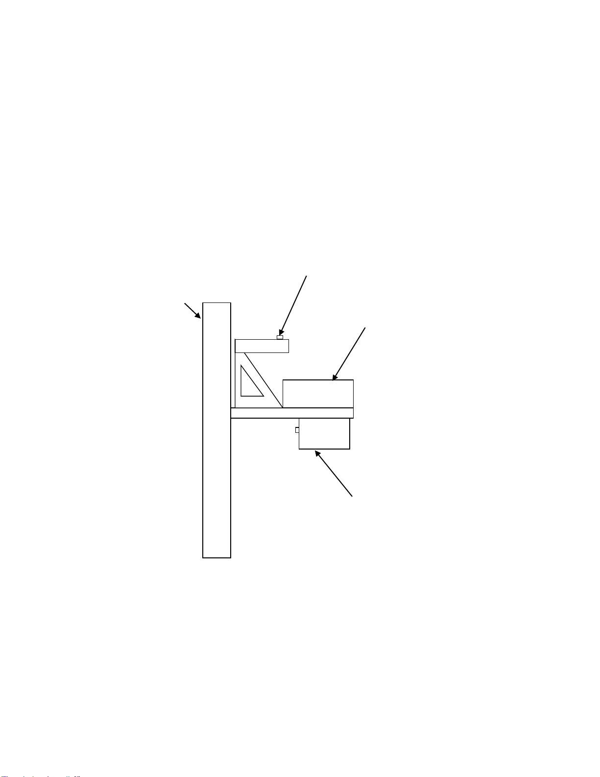
Pic 1. Layout of the device. The device consists of electronic module (1), permanently affixed to the 24 inch bar
(2), which contains fluxgate sensors at both ends, battery module with the power switch (3), and handle (4) with
“Enter” button.

2
3
1
4
5
6
OK
Menu
MG 200
Pic 2. Electronic module. Front panel MG-200
Front panel of the electronic module contains display and six control buttons. Button functions change
depending on which mode the device is in: “MENU” or “OPERATION”.
“MENU” Mode:
Button 1 –“MENU” switches between modes “MENU” – “OPERATION”;
Button 2 –← “LEFT”;
Button 3 –↑“UP”;
Button 4 –“OK” (”Enter”)
Button 5 –→”RIGHT”
Button 6 –↓“DOWN”
Button 7 (top part of the device handle, not shown in Pic. 2) works as “OK” (“ENTER”) during MENU
functions –BALANCING and ALIGNMENT
During “OPERATION” mode button functions are as follows:
Button 1 –switches between modes “MENU” – “OPERATION”;

Button 2 –←Demagnetize;
Button 3 –↑Filtering
Button 4 –“OK” Sound Volume
Button 5 –→Sensitivity;
Button 6 –↓Correction of “0”
Button 7 (top part of the device handle) –reset device measurements to “0”
ON/OFF Power switch is located on the battery module of the device.
3.2 Menu mode “MENU”
Turn the power on with the switch on the battery module. After flashing the line “Gradiometer MG-
200”, top line of the two-line display will read: “Sens. 1 (or 0.1) Filtr. 0 (or 1.2)” and level of the battery
charge ≤≤≤; the bottom line will display: “MENU”↓ - “OPERATION” →. Arrows show pressing of which
buttons will take you to the menu mode “MENU” or “OPERATION”. Familiarize yourself with Menu and
tune the device for your search goals.
By pressing button 1 to switch into menu mode “MENU” and then button 6↓ you can scroll through the
following parameters:
Correction of “0”. Correction of “0” is performed to compensate for the temperature drift. It means that
the readings will “drift” while the still device is warming up or cooling down. “Drift” is especially
noticeable during the first 20-30 minutes of operation, until the temperatures inside and outside the
device equalize. After this the “drift” either stops or is miniscule enough to control it by pressing from
time to time button 7 (reset device measurements to “0”). However if the drift is interfering with search
operation anyway, you should use automatic correction. While in “MENU” parameter “Correction of “0”,
press button 4 “OK” and by pressing button 5→ choose the correction level from 1 to 10, which
sufficiently cancels out the drift. In most cases level 3 through 6 is sufficient. You shouldn’t pick the level
higher than the one needed. Manufacturer’s default setting is 3.
“Filtering”–is used to weed out the influence of metallic trash. With setting at 0.5 all anomalies smaller
than 0.5 meter in plan are ignored, at 1 –less than one meter, at 2 –less than 2 meters. With setting at
“0” – Filtering is turned off. Top line of display will show the current level of Filtering as F 0 when
Filtering is off, and F 0.5, F 1, or F 2 when Filtering is on. When exiting this setting through “OK” button
the setting will remain active for the following sessions of the device; when exiting through button
“MENU” – only during the current session.
Filtering works best during movement. During stops or slow movement filtering becomes less effective.

Filtering can also be performed by the amplitude of the anomalies by choosing the threshold for sound
signal activation. More on this in the part “Sound regulation”.
“Sensitivity”. With the help of buttons 4 ”OK”, 2 ←, and 5 →, set the desired sensitivity. Its level will be
shown on display during “OPERATION” mode as “Sens 1” or “Sens 0.1”. Sensitivity 1 is recommended
during most types of searches, since sensitivity 0.1 has inertia of about 1 second. It means that the
measurements are still taken 10 times per second but are delayed in the direction of movement by 1
second.
By exiting through “OK” the setting is saved for the following sessions. By exiting through “MENU” only
during current session.
“Balancing”–tuning of identical sensitivity of sensors. Balancing is performed if the reaction of
magnetometer to 5-10 degree tilt from the vertical position during movement is more than 5-10 units
and if it interferes with the search. This operation is described in detail in Part “Tuning of Gradiometer”
“Alignment”of the sensors. If after you change the direction of movement a constant level of field is
displayed, you can reset it by pressing button 7 (reset measurements to “0”). However if the field
reading changes by more than 5-10 units when making a 5-10 degree turn, and it interferes with the
search, alignment of sensors should be performed. This operation is described in detail in Part “Tuning
of Gradiometer”
“Save parameters” –is used to save new settings of “Balancing” and “Alignment” for the following
sessions of operation by pressing button 4 “OK”.
“Backlight” –after pressing “OK” use buttons 2 and 5 to adjust the necessary level of backlight.
“Contrast” –after pressing “OK” use buttons 2 and 5 to adjust the necessary level of display contrast.
“Sound regulation” –after pressing “OK” use buttons 2 and 5 to choose whether to adjust the volume
of the sound or the threshold for sound activation. Press “OK”, then use the same buttons –2 and 5 to
set the necessary sound volume or threshold level.
Threshold of sound activation is the value of the gradient, measured in units, beginning with which
sound will be played. The threshold is determined by the user and depends on the minimal expected
amplitude of the needed anomaly.
“Default settings” –by pressing “OK” button twice you revert the device to manufacturer’s default
settings, including “Balancing” and “Alignment” settings. Below are manufacturer’s default settings:
Correction of “0” – 3;
Filtering –0;
Sensitivity –1 unit;

Backlight –4;
Contrast –9;
Sound regulation:
Volume –4;
Threshold for sound activation:
Sensitivity 1 unit –10 units;
Sensitivity 0.1 unit –2 units.

3.3 Menu Mode “OPERATION”
With mode change –buttons’ functions change too. All parameters set in “OPERATION” mode will
remain active during current session of work only. After turning gradiometer off and back on,
parameters set earlier during “MENU” mode are automatically restored.
Button 1 –switch between menu modes “MENU” – “OPERATION”
Button 2 ←–“Demagnetize” is used to manually return sensors to the work condition after accidental
magnetization in a strong magnetic field. For example when passing close to a car (within 10 feet) or
another source of a strong magnetic field. When tilting the device more than 30 degrees it’s possible to
magnetize the sensors by powerful magnetic field of earth. The device demagnetizes automatically
when it is turned on. Button 2 demagnetization should be performed away from sources of strong
magnetic field. After demagnetization, press button 7 to reset device measurements to 0.
Button 3 ↑–“Filtering” allows to set filters that lower the influence of metal trash.
Button 4 “OK” – “Sound Volume” has 11 levels from 0 (Mute) to 10 (Maximum volume). Chosen
parameter will remain active only during current session.
Button 5 →–“Sensitivity” allows to choose sensitivity setting - 1 or 0.1 unit. Chosen sensitivity will
remain active only during current session.
Button 6 ↓–correction of “0”. Removes temperature “drift” of “0”, has 10 levels (level 3 is set by
default). Chosen correction will remain active only during current session.
Button 7 –“Reset to “0” – located on the device handle is used to reset all device measurements to “0”.
All further measurements will be performed from this “0” level.
3.4 Field work and search with gradiometer.
Before beginning work, get rid of all magnetic objects –phone, keys, credit cards, etc.
1Turn the device on with a switch on the battery compartment.
2Use button 5 → to switch to “OPERATION” (or return through “MENU”). Display will show “WAIT”
and start countdown to powering up (6 seconds total). During this time the device tunes all systems,
demagnetizes sensors, and calculates gradient of the magnetic field. Then it displays on the screen
the gradient reading, its sign: + (positive) or –(negative), settings for “Filtering”, “Sensitivity”, and
levels of battery charge: fully charged ≥≥≥ (over 75%); ≥≥ (over 50%); ≥ (less than 10%); blinking sign
≤≤≤ means that batteries need to be charged.

Check for the absence of magnetic objects by moving the device along your body (holding
gradiometer vertical to the ground).
3If necessary, select new parameters for operation. Use button 1 to switch to “MENU” and choose
the desired backlight, brightness, and contrast. Remember that with backlight turned on, battery
time will be 5% less. Switch to “Sound regulation” and select the desired volume and sound
threshold (default setting 10 units for sensitivity level 1, and 2 units for sensitivity level 0.1). If
needed choose appropriate “Filtering” and “Correction of “0”. To save the selected settings for the
following sessions, exit each parameter by pressing “OK”.
Leave the device in “Operation” mode for 20 minutes to warm up all electronics and sensors.
After warm up is complete check settings for “Balancing” and “Alignment”. To do this pick a spot
with weak magnetic field gradient (no more than 2-3 units). Perform demagnetization with button 2
← and reset readings to “0” with button 7.
First check balancing of sensors: turn to face North, reset readings to “0” (button 7), and tilt the top
part of the gradiometer 3-5 degrees to the North, then to the South. Make sure the measurements
do not change by more than 5-10 units, or remain at the level that will not interfere with search (no
more than 5 units).
Now check alignment of the sensors: holding the device vertically (without tilting) turn to the North,
East, South, and West. Make sure the changes in readings are small enough not to interfere with the
search.
If necessary perform “Alignment” and “Balancing” tuning procedures as described in Part 4 of the
manual. If no tuning is necessary, you can begin work.
4Begin search: Stand at the beginning of the route, reset to “0” with button 7 and start moving.
During movement you can change without switching to “MENU” the following – sensitivity, filtering,
sound volume, correction of “0”.
5During movement try to always hold the device vertically without tilting and turning. If you turn
abruptly the device may register a small constant level of magnetic field caused by poor alignment
tuning. Simply reset it by pressing button 7 on the handle and continue movement.
Movement can be performed at any speed allowing to hold the device vertically.
It is better to search the area along parallel routes. The distance between the routes is determined
by the size of the expected anomaly that you are searching for. The routes must guarantee crossing
the anomaly at least twice. For example, if the needed anomaly is approximately 4 meters (12 feet),
the distance between routes must be no more than 2 meters (6 feet). To guarantee quality of

search, you can move along previously stretched parallel wires. You can also move along one wire
that is being moved parallel across needed intervals.
3.5 Locating objects
When you find anomaly - stop, find maximum, and cross it one more time in a perpendicular direction.
Center of anomaly is the point of passing through “0” between maximum positive and negative gradient.
Below this point lies either the center of the object or its closest to the surface part. To better locate the
center of the object, turn Filtering off.
If the object is compact and monolithic (not a ravel of wire or cable), its approximate depth is 30-50% of
the anomaly’s width.

Part 4. Gradiometer Tuning
There are only two types of tuning: if there is interference from tilts, balancing of sensors is needed; if
the interference is from turns, alignment of sensors is needed. These tunings are rather simple,
performed as needed, and after a little practice take about a minute for balancing, and a few minutes
for alignment.
Most of the time interference caused by poor alignment is not high and is presented as a low level of
constant field when moving along the route. It can be removed by pressing button 7, resetting field level
to “0” after changing the direction of movement. If however, this is not enough, perform alignment
tuning as described below.
The need for tuning should be determined by the user, taking into account what level of interference he
considers acceptable for this particular search. Normally it means 1-2 tunings a day.
When tuning might be needed:
Interference from 3-5 degree vertical tilts while moving is over 3-5 units (Balancing is needed)
Interference from 3-5 degree horizontal turns (change of direction during movement) is over 3-5
units (Alignment is needed)
Always perform Balancing first.

4.3 Balancing
1Pick an area approximately 5 by 5 feet that has no field gradient (gradient change is no more than 2-
3 units)
2Get rid of magnetic objects –cell phone, keys, screw drivers, metal fasteners on clothes, shoes,
glasses, credit cards, watch, etc.
3Pick “Balancing” option in the menu. Press “OK”. Letter “N” (North) will begin to blink. Orient device
to the North while holding it vertical to the ground. Tilt the top end of the device to the North
several degrees until the device registers a reading of 3-5 units (Pic. 3a), press button 7.
N s
Pic. 3a Balancing. Tilt to the North Pic. 3b Balancing. Tilt to the South
4Letter “S” (South) will begin to blink. Tilt the top end of the device to the South to a similar angle (do
not rotate the entire device to face South!) until the device registers a reading of 3-5 units (Pic 3b),
press button 7 and return the device to the vertical position. The screen will read “Calculating” and
the device will reset to “0”.
5Repeat paragraphs 3 and 4 again, but with smaller tilts so that the change in readings is no more
than 1 unit.
If the screen says “Surpassed regulation zone” it means that the tilt angle was too big and the
difference between North and South readings surpassed the allowable 200 unit level. Repeat
paragraphs 3, 4, and 5, but tilt the device to a smaller degree.

6A situation is possible when tilts to North and South give very similar results both by value and by
sign and vertical position reads “0”. For example, tilt to the North gives a reading of +5, vertical
reading is 0, and tilt to the South +4. Processor cannot improve the tuning with such data. In such
cases instead of two tilts –one to the North and one to the South, tilt only to the North or only to
the South and instead of the second tilt hold the device vertically. The processor will calculate
between one tilt and “0” and improve the result.
7Check balancing by tilting the device to the North and the South. A well-tuned balance is when tilts
of 3-5 degrees do not surpass +-1-2 units.
8After you are done with balancing, return to “Menu”, choose “Save Parameters”, and save current
balancing by pressing “OK”. Switch back to “Operation” or continue tunings my moving on to
alignment.

4.3 Alignment
On a 5 by 5 foot area free of anomalies check the readings of the device while turning around. You need
to see the difference in readings between North and South, and East and West. While turning the
sensors should be located above the center of the chosen area and the device is held vertically. Begin
alignment from the pair of directions where the spread of readings is larger.
1Enter the Alignment mode and press button 7 “OK”.
2Choose the pair of directions that has larger spread in readings –North-South or East-West using
buttons 2←or 5→. If for example, the spread is larger in the direction of North-South, press button
2←. “North” will begin to blink.
3Orient the device to the North (the device is held vertically during the entire tuning procedure).
Press 7 “OK”. Instead of “North”, “South” will begin to blink.
4Orient the device to the South, press 7 “OK” (Pic. 4 a,b).
If the screen says “Surpassed regulation zone”, it means that the difference between measurements
in opposite directions surpassed 100 units. Repeat paragraphs 3 and 4 but without completing a full
turn so that the difference between directions is no more than 100 units.
5Check the result by orienting to the “North”. Continue repeating paragraphs 3-5 until difference in
measurements between positions to the North and to the South is no more than 2-3 units.
6Perform the same procedure in the direction of East-West. After finishing check the reaction of the
device in all directions once more. Correct again if needed.
7Return to Menu and save the settings through “Save Parameters”.
Return to “Balancing” and check it too.
If during alignment tuning you turn in the wrong direction and press “OK”, the device will calculate
wrong data and show the result that will be too high and difficult to refine. This can happen during
either alignment or balancing.
In this case simply choose through Menu “Default Settings”, press 7 ”OK”, and repeat balancing and (or)
alignment tuning again.

N S
Pic. 4a Alignment. Orientation to the North Pic. 4b Alignment. Orientation to the South

Part 5 Frequently Asked Questions
If the magnetic field gradient reaches 500 units or more, or during operation the device is tilted more
than 30-40 degrees, the sensors might become “magnetized” and will show a constant level of field. In
this case after leaving the anomaly area (or after bringing the device back into vertical position) simply
press button 2←“Demagnetize” and 7 “Reset to “0”.
If the surrounding temperature drops below freezing or when the batteries are running out of charge,
display may lose its contrast. Choose the “Contrast” parameter in the Menu and correct its level. Also
during strong frosts LCD display might become slower to respond due to freezing of liquid inside of it.
This however, does not affect operational ability of the device or the sound indication.
Caution
Protect the device from moisture, chemicals, and mechanical stress. Do not open the device.
Operational temperature range is +50C (122F) to -15C (5F). Storage temperature up to -30C (-22F)
Manufacturer Warranty
Upon following the rules described in this manual, warranty runs for two years from the date of sale.
Warranty does not cover batteries. Cost of shipping for repairs including those under warranty is
covered by the owner and at his expense.
The seller is not responsible for losses incurred by the owner in case he is unable to use the device due
to its malfunction.
Full technical support is provided via phone or email for free. If you have a question, refer to this User
Manual first. Main text of it contains various help and advice.
If you cannot find the answer to your question please refer to our website www.magnotracker.com for
technical support or give us a call at 760-536-2543
When you call or contact us by email, please provide the following information:
Your name, name of your company, your contact information and serial number of your device
(it is briefly shown in the right part of display when power is turned on).
Detailed information about your request. Please be as specific as possible.
Date Signature
PROFEX electronics
New York, USA
Table of contents


