Profibus PB-Q ONE User manual


Revision overview
PB-QONE - User Manual 3
Revision overview
Date
Revision
Change(s)
10/10/2017
0
First version
© Copyright 2017 Indu-Sol GmbH
We reserve the right to amend this document without notice. We continuously work on further developing
our products. We reserve the right to make changes to the scope of supply in terms of form, features and
technology. No claims can be derived from the specifications, illustrations or descriptions in this
documentation. Any kind of reproduction, subsequent editing or translation of this document, as well as
excerpts from it, requires the written consent of Indu-Sol GmbH. All rights under copyright law are expressly
reserved for Indu-Sol GmbH.

Contents
PB-QONE - User Manual 4
Contents
Revision overview 3
Contents 4
1Introduction 6
1.1 General 6
1.2 Functional overview 6
1.3 Scope of supply 7
1.4 System requirements 8
1.5 Safety information 8
2Commissioning 9
2.1 Software installation 9
2.2 Connect device to PC 9
3Connection to the PROFIBUS system 10
3.1 Basics 10
3.1.1 Warning about measurements on running systems 10
3.1.2 Connection types for PROFIBUS devices 10
3.1.3 Adapter cable 10
3.1.4 Measuring locations 11
3.2 Connection versions 12
3.2.1Measurements during system downtime 12
3.2.2 Measurements on the running system 13
3.2.2.1 Connection type D-Sub connector with service jack 13
3.2.2.2 Connection via permanently installed measuring point PBMA (IP20) 14
3.2.2.3 Connection type M12 (IP67) 15
4Perform and document measurement 16
4.1 General information 16
4.2 Network 17
4.2.1 Topology 17
4.2.2 Device list 19
4.2.3 List of measuring points 19
4.3 Quality values 20
4.3.1 Standard measurement 20
4.3.2 Additional functions 21
5Telegrams 22

PB-QONE - User Manual 5
6Results 24
6.1 Network overview 24
6.2 Device details 25
6.3 Event list 26
6.4 Comparison 26
7Report 27
8Technical data 28
8.1 Technical drawing 28
9Appendix 29
9.1 Sample log 29
9.2 Sample plan 31

Introduction
PB-QONE - User Manual 6
1 Introduction
1.1 General
The PB-QONE is an easy to use, powerful measuring device for comprehensive inspection of PROFIBUS
master systems. It offers separate testing of the physical condition of the bus (signal quality) and the
telegram traffic. The device can be used for acceptance measurement on new systems for inclusion in the
acceptance report, as well as for targeted troubleshooting of existing systems.
Its integrated master simulator enables testing of the communication quality without a need for the PLC to
be operational. This enables pre-inspection of complete systems and their parts during the commissioning
stage, with the goal of providing stable bus systems for trouble-free production in the long term.
The device is connected to a PC or notebook via a USB interface, which also provides the power supply. It
is controlled with the “Indu-Sol Suite” software.
1.2 Functional overview
The PB-QONE is designed to assist you with inspection, troubleshooting, and the isolation of root causes.
To this end, it offers the following functions:
Feedback-free bus coupling at suitable existing measuring points during running operation
Automatic detection of the baud rate
Automatic identification of all devices on a bus system (LiveList)
Device and measuring-point-based display of signal ratios:
oGeneral quality value
oSignal to noise ratio and slope gradient
oOscilloscope display with selection options for detailed evaluation
Long-term monitoring of all devices (continuous measurement) with minimum, maximum, and average
quality values
Editable measuring point and segment management
Wear inspection by comparing current readings with stored measurements
Integrated master simulator for inspection of system without a master (commissioning phase)
Real-time monitoring of the entire data traffic and checking for telegram errors, with entries into the
event list
In-depth telegram analysis with option for variable trigger setting
Easy documentation of measurements in the form of an acceptance report and topology plan
Introduction
PB-QONE - User Manual 7
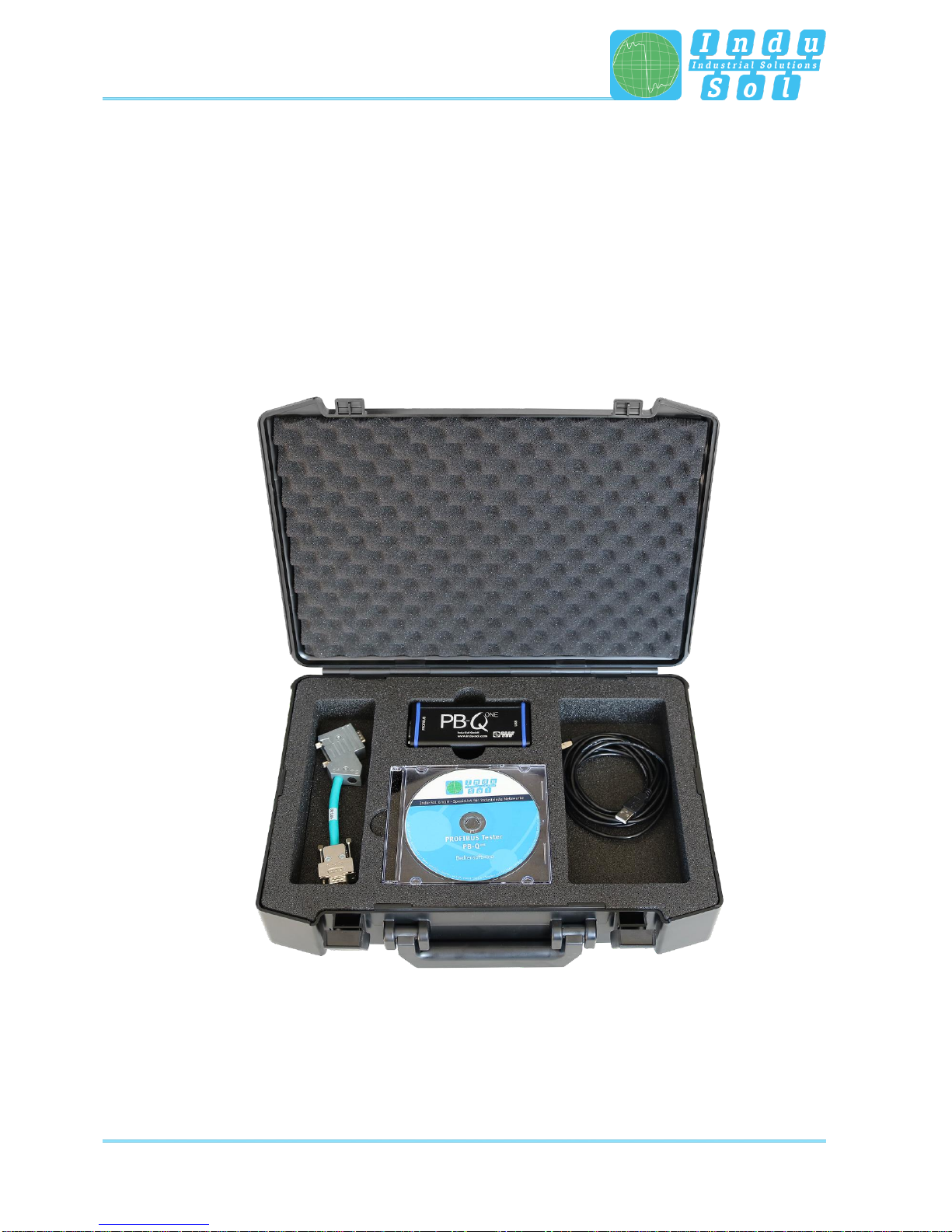
1.3 Scope of supply
The scope of supply comprises the following individual parts:
Measuring device PB-QONE
D-Sub 9-pin adapter cable (for connecting to a PROFIBUS system)
USB cable (2 m)
CD with operating software “Indu-Sol Suite” and device manual
Please check the contents are complete before putting into operation.
Figure 1: PB-QONE delivery condition

Introduction
PB-QONE - User Manual 8
1.4 System requirements
The following Windows versions are supported: Windows 7, Windows 8, Windows 10.
The following minimum hardware requirements apply for the PC or notebook used:
CPU: Dual Core, Core I3 or better
RAM: 4 GB
Screen resolution: ≥ 1024x768 pixels (XGA)
Graphics: DirectX 9.0c capable graphic board (supported by most on-board
graphic boards)
USB interface: 2.0 (no other devices should be connected to the USB hub)
1.5 Safety information
Never open the housing of the PB-QONE
Opening the housing immediately voids any warranty
If you suspect that the device is defective, then return it to the supplier

Commissioning
PB-QONE - User Manual 9
2 Commissioning
2.1 Software installation
The PC software “Indu-Sol Suite” includes the required USB driver and needs to be installed on
the PC or notebook before the PB-QONE is connected for the first time.
The “Indu-Sol Suite” software is included on a CD-ROM. The installation requires administrator rights. If the
CD-ROM does not start automatically after inserting, then manually start the “setup.exe” file in the main
directory.
Future updates can be found on the Internet at www.indu-sol.com, under downloads.
The installation is performed after selecting the language, agreeing to the end user licence agreement, and
making the installation settings. Then the software is fully available for the following measurements.
2.2 Connect device to PC
Use the included USB cable for connection to the PC or notebook, including power supply.
Preferably connect the device directly to a USB port on the PC or notebook. Connecting via
external USB hubs or docking stations of notebooks may cause problems.
Connection to the PROFIBUS system
PB-QONE - User Manual 10
3 Connection to the PROFIBUS system
3.1 Basics
3.1.1 Warning about measurements on running systems
Caution: When connecting a measuring device, effects on the system to be inspected cannot be
ruled out completely. With unstable PROFIBUS systems, malfunctions of the system may occur
in rare cases. Always observe the connection information!
3.1.2 Connection types for PROFIBUS devices
Depending on the device version, there are different ways to connect bus modules to a PROFIBUS network:
Connecting via plug-in connectors
oD-Sub plug-in connector, usually with an integrated terminal resistor, and optionally with an
additional service jack
oM12 screw-in connector in the field for higher IP ratings
oSpecial manufacturer-specific hybrid plug-in connectors for routing the power supply over the bus
in conjunction with special cables
Direct cable connection via terminals
Due to the typical linear structure of the PB networks, the available measuring points are usually limited to
the connecting points of the bus devices. Alternatively, the use of additional measuring points (e.g. Profibus
measurement adapter, PBMA) may be viable.
3.1.3 Adapter cable
The standard scope of supply of the PB-QONE includes the 9-pin D-Sub adapter cable. An M12 adapter kit
is available as an optional accessory.
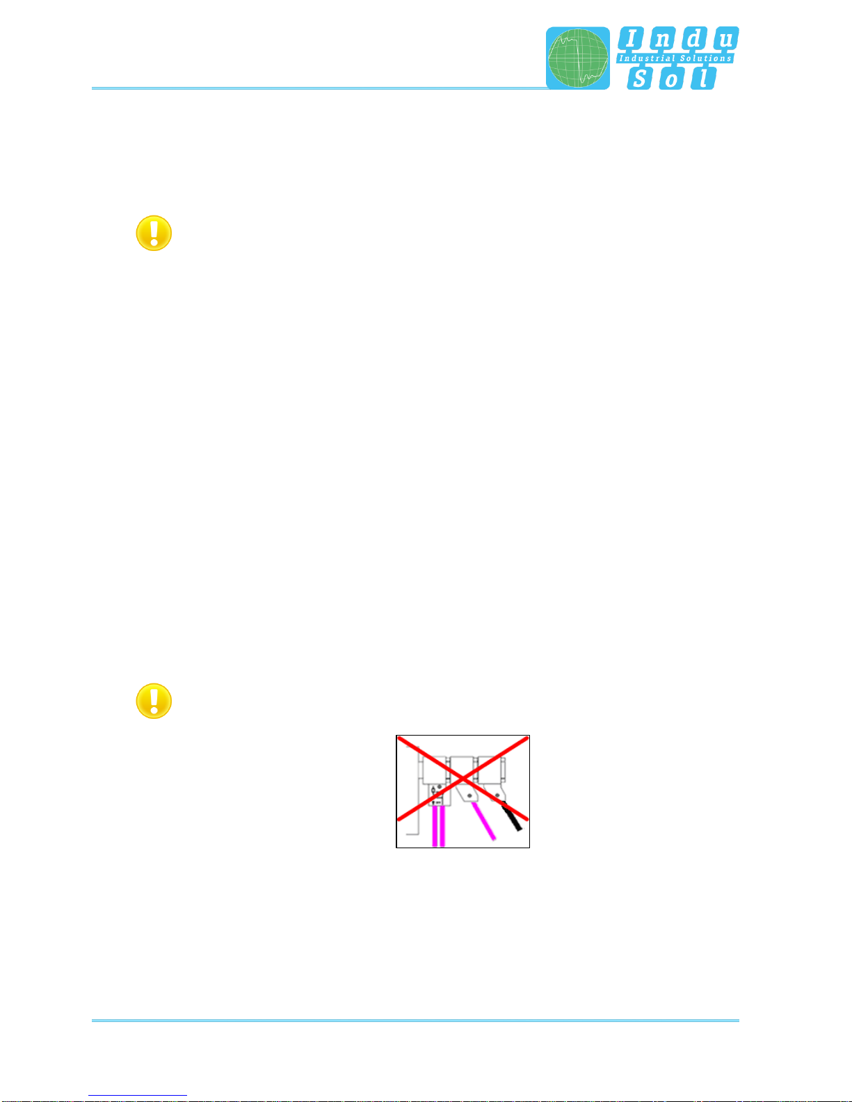
Use only the short original cables with special pin allocation for connecting to a PROFIBUS
network. No more than two D-Sub connectors must be cascaded to the service jack at a time.
Figure 2: Improper cascading of D-Sub connectors
The use of active connecting cables with integrated repeaters for measurement is not possible.

Connection to the PROFIBUS system
PB-QONE - User Manual 11
3.1.4 Measuring locations
In principle, the PB-QONE is able to perform measurements at any point in a PROFIBUS system. Please
note that the use of repeaters and converters (OLM, data light barriers, wireless transmission) creates
separate physical segments that need to be evaluated individually.
A complete and in-depth analysis of the overall PROFIBUS system requires measurements to be performed
at the beginning and the end of each physical segment. If problems are detected that cannot immediately
be classified clearly, then at least one additional measurement should be performed in the middle.
Connection to the PROFIBUS system
PB-QONE - User Manual 12
3.2 Connection versions
3.2.1 Measurements during system downtime
If D-Sub connectors with an additional service jack are present on all bus devices, then the
PB-QONE is simply connected there as shown in the image. If a D-Sub connector without a service jack is
installed, then the D-Sub adapter cable can be inserted below. Note that cascading more than two D-Sub
connectors should be avoided at all cost.
For M12 connection technology, the M12 adapter cable (optional) is looped into the bus.
For all connection versions requiring adapter installation, the bus must be opened. This causes
short-term disruptions in communication, which is why a system shutdown is required.
Figure 3: Measuring points during system downtime

Connection to the PROFIBUS system
PB-QONE - User Manual 13
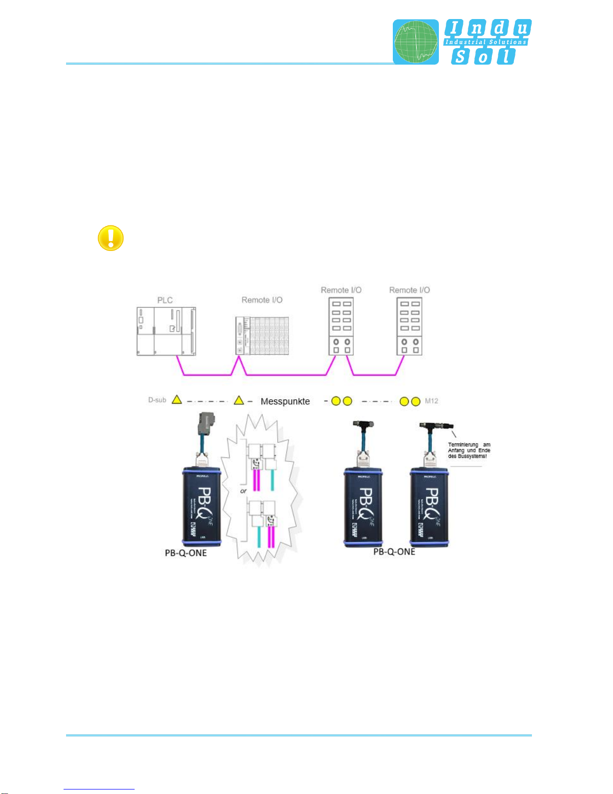
3.2.2 Measurements on the running system
No intervention into the master system is possible on running systems, as this would automatically lead to
bus faults and loss of production. The PB-QONE can only be connected and run at the existing measuring
points (e.g. PB connector with service jack on the CPU). In order to be able to perform a status quo analysis
under production conditions on all existing segment ends, this should be considered during the system
planning stage. If the use of appropriate connectors is not possible, then measuring adapters (e.g. PBMA
–IP20, PBMX –IP67) can be used.
3.2.2.1 Connection type D-Sub connector with service jack
If D-Sub connectors with an additional service jack are installed on all bus devices, then the PB-QONE is
simply connected there as shown in the image.
Figure 4: Measuring points via the service jack
Connection to the PROFIBUS system
PB-QONE - User Manual 14
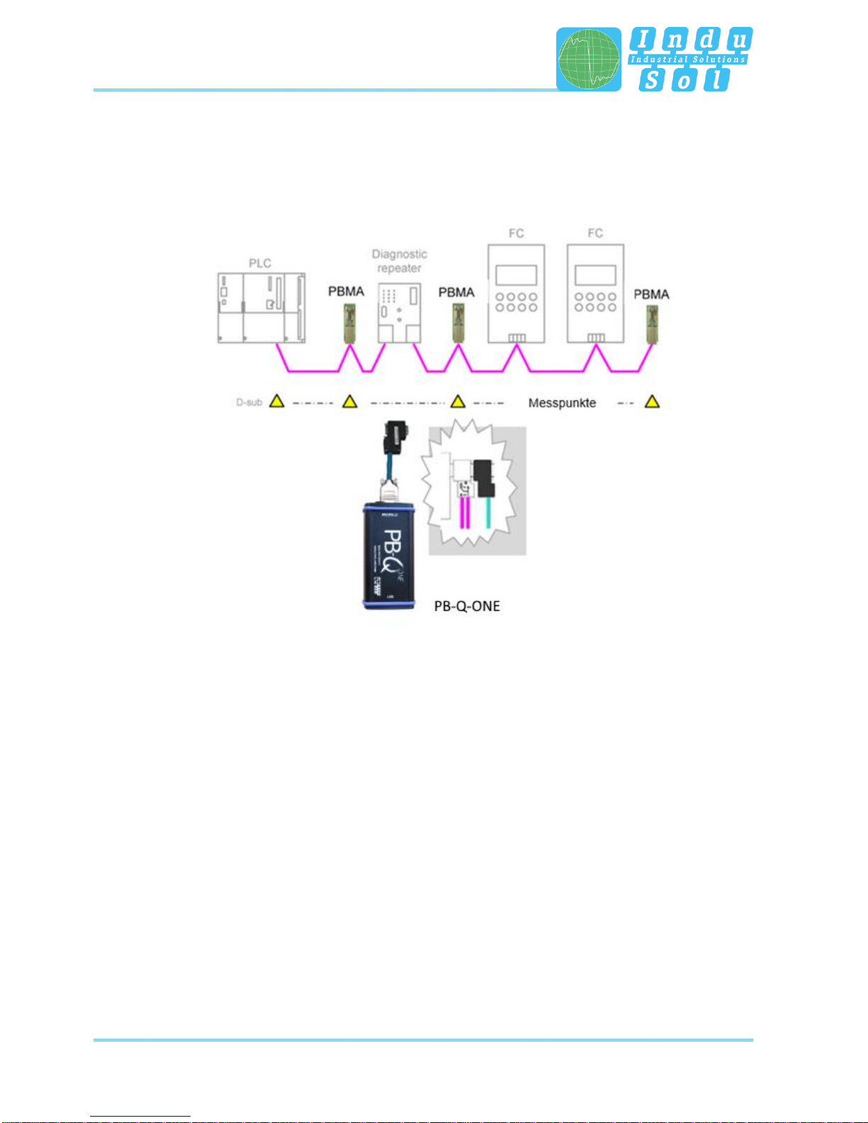
3.2.2.2 Connection via permanently installed measuring point PBMA (IP20)
For measurement during running operation, Profibus measuring adapters (PBMA) have been permanently
integrated into the system.
Figure 5: Example of permanently installed measuring points (PBMA)
Connection to the PROFIBUS system
PB-QONE - User Manual 15
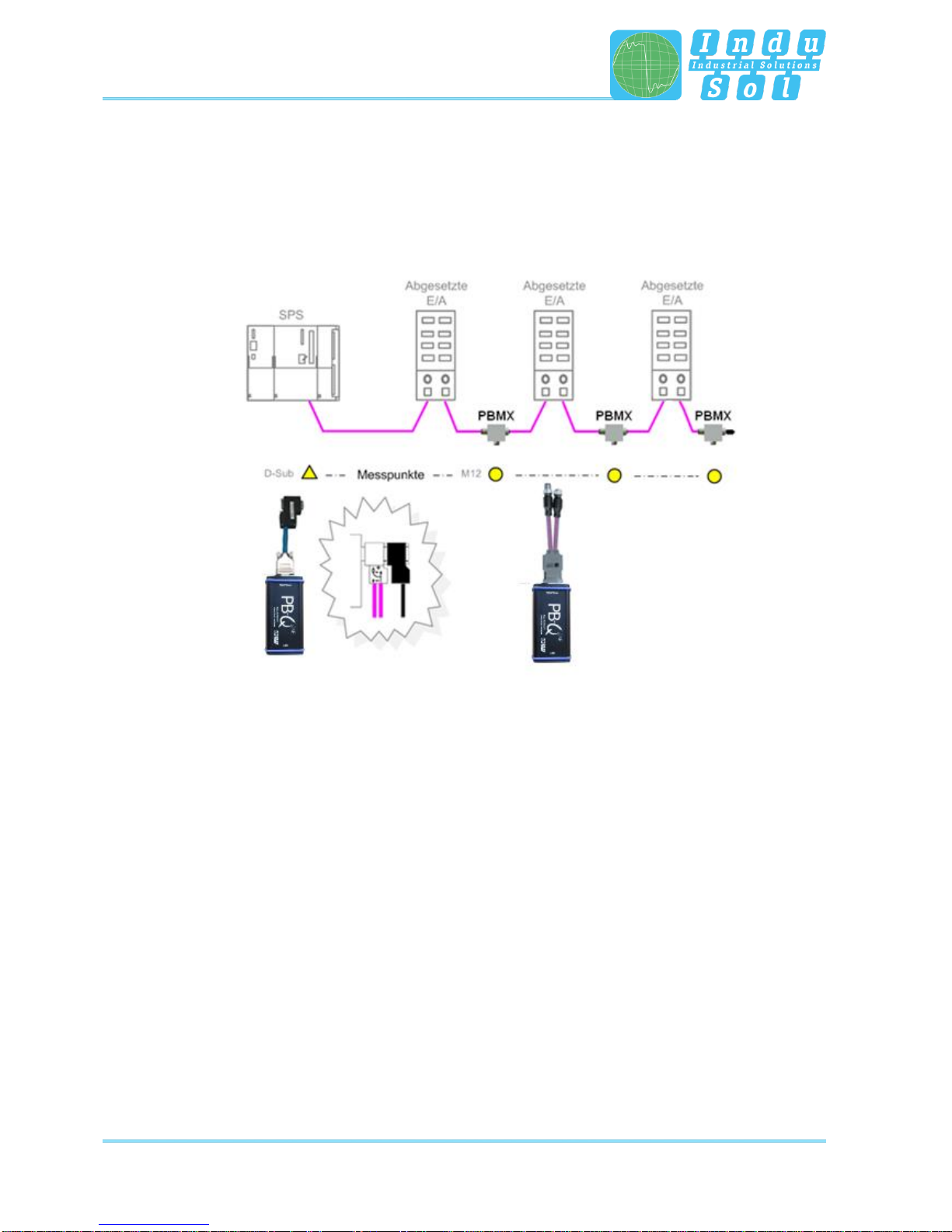
3.2.2.3 Connection type M12 (IP67)
For measurement during running operation under IP67 conditions, Profibus measuring adapters (PBMX)
have been permanently integrated into the system. An M12 adapter (optional) is required for connecting
measuring devices.
Figure 6: Example of permanently installed IP 67 measuring points (PBMX)
Perform and document measurement
PB-QONE - User Manual 16
4 Perform and document measurement
4.1 General information
All measurements taken with PB-QONE and the respective entries are summarized in a measurement file
(*.pbn) for storage and later retrieval. For a structured analysis of several systems, it is therefore useful to
create a separate measurement file for each master system. It can be used as a basis for additional
measurements later to provide an easy way of performing before-after comparisons.
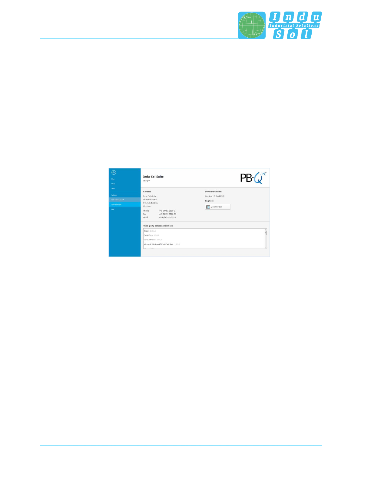
The system language can be selected between English and German under “Settings”.
In “GSD management”, the *.gsd files of each Profibus device are stored in the system. This file defines
the characteristic communication features of the relevant slave. The PB-QONE uses this information for
detecting the device type as well as manufacturer-specific information.
Figure 7: File management
Perform and document measurement
PB-QONE - User Manual 17
4.2 Network
4.2.1 Topology
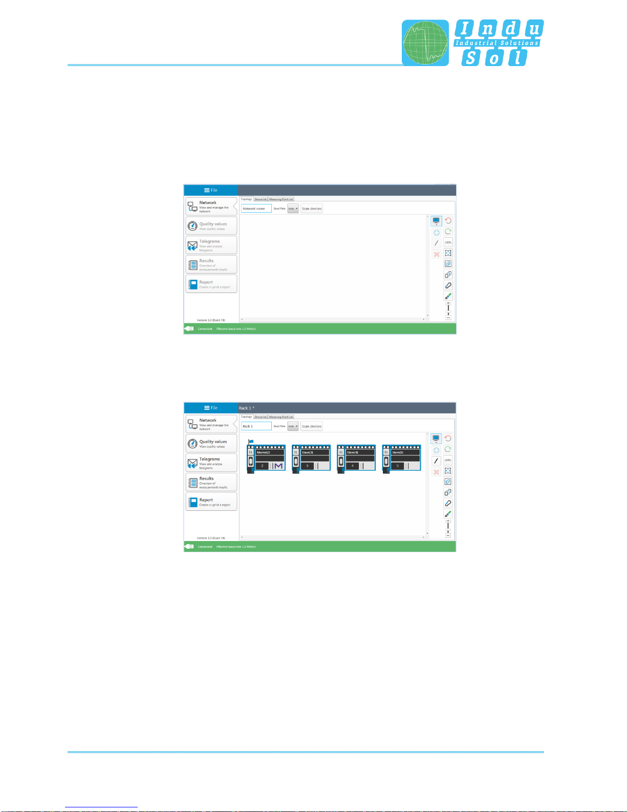
After connecting the PB-QONE to the computer via USB, connecting the measuring adapter to the Profibus
system, and starting the software, the network overview is displayed with the detected baud rate
(Figure 8).
Figure 8: Home screen
The system designation can be entered in the field “Network name”. The function “Scan devices” lists the
detected devices in ascending order of address (Figure 9). This is the basis for future measurement steps.
Figure 9: Device list
Perform and document measurement
PB-QONE - User Manual 18
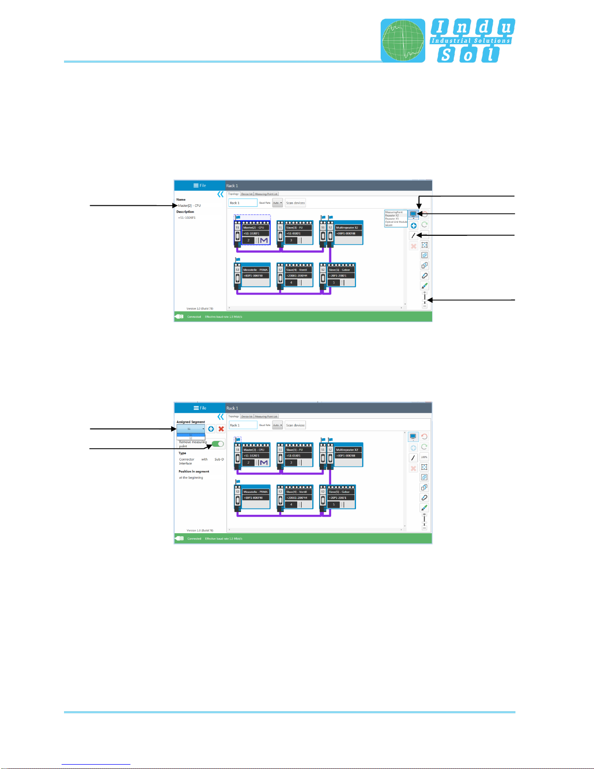
The topology plan is a prerequisite for structured measurements and creating a detailed system description.
In the topology overview, a complete representation of the actual system structure with device descriptions,
segmentation and measuring points can be realised. Selecting individual devices enables more detailed
naming (e.g. with device type, equipment identifier). The tools in the drop-down menu enable the integration
of additional modules without a dedicated Profibus address (measuring points, repeaters, optical fibre
converters, wireless converters) and the connection of the overall system (Figure 10).
Figure 10: Topology
Segment and measuring points are assigned by selecting the relevant connection points of the end devices.
After defining the measuring point and allocation to a segment, the relevant segment number is
automatically assigned to all modules connected in this segment (Figure 11).
Figure 11: Assign measuring points
Device selection
Create connections
Editing the
highlighted device
Drop-down
menu
Zoom
Segment selection
Assign measuring
point
Perform and document measurement
PB-QONE - User Manual 19
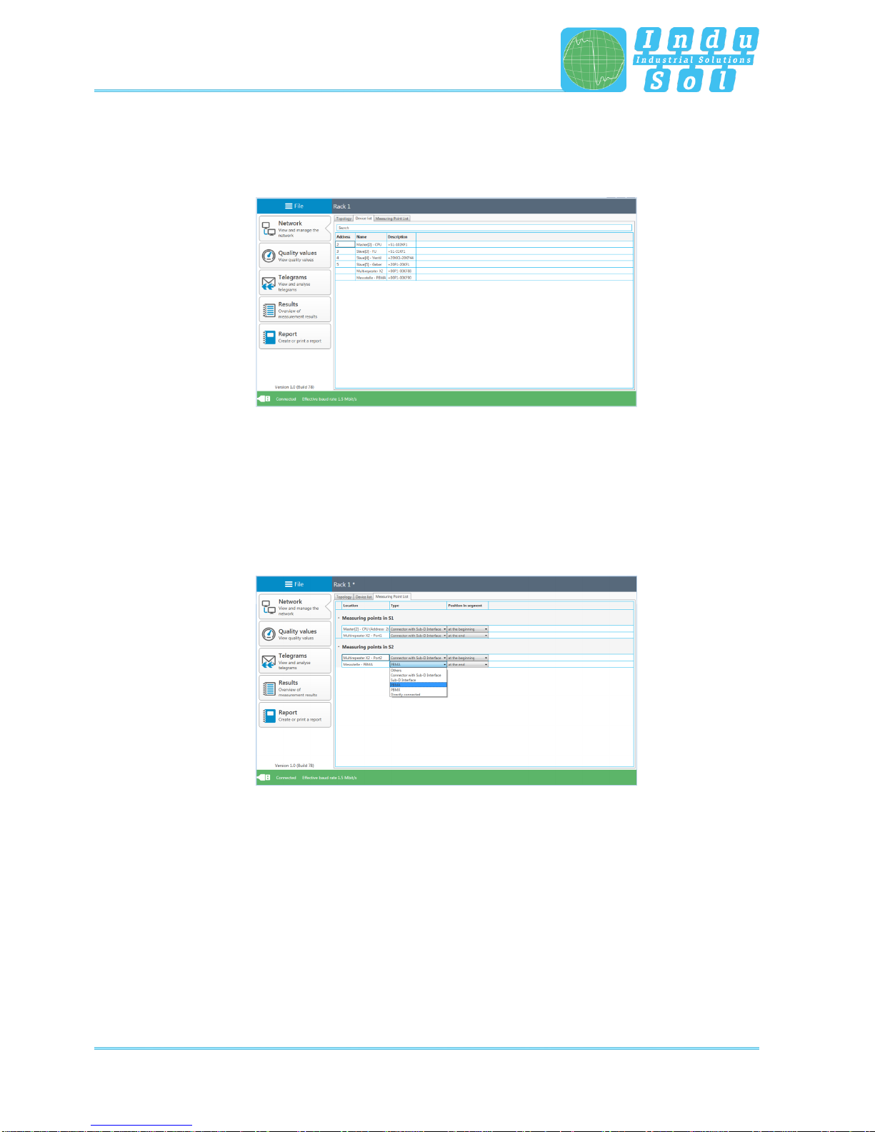
4.2.2 Device list
The “Device list” sub-item provides a complete overview of all topology entries in table form. Inputs as well
as search and sorting functions can be performed here.
Figure 12: Device list
4.2.3 List of measuring points
The list of measuring points is a segment-specific overview of all measuring points in the system. The
entries in the “Topology” tab are the starting point. For completion and better definition of the list, the
measuring point type (e.g. connector with Sub-D interface, PBMA) as well as the position on the segment
(at the beginning or end) can be assigned via the relevant drop-down menu.
Figure 13: List of measuring points
Perform and document measurement
PB-QONE - User Manual 20
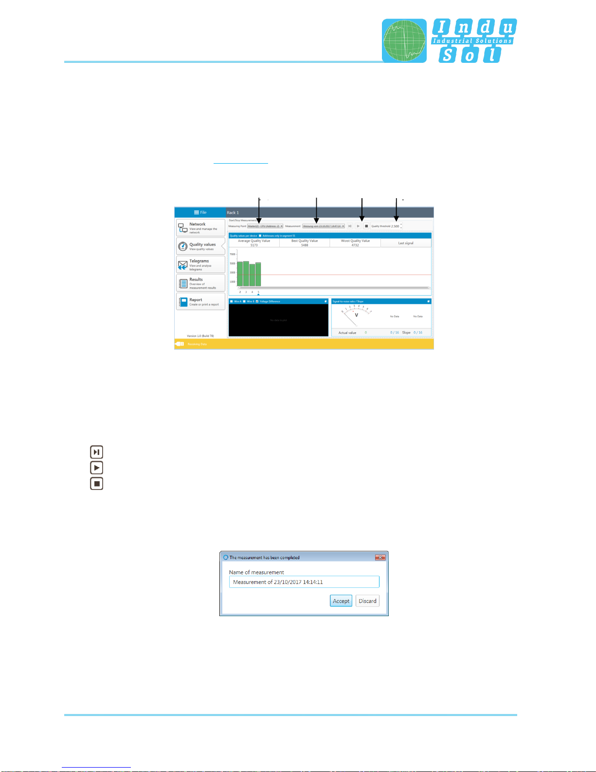
4.3 Quality values
4.3.1 Standard measurement
The quality values represent the main criterion for evaluating the physical communication conditions. For a
complete system analysis, measurements need to be performed in all segments on both ends. The device
addresses determined by the “Scan devices” function serve as a reference.
Figure 14: Quality values
Select the measuring point before starting the measurement. Finally, press the relevant start button to
decide whether to perform a single or a continuous measurement. Clicking on the stop button terminates
these functions and displays the results of the quality values for the overall system. The icons used have
the following meaning:
Start new single measurement (single cycle with all device addresses)
Start new continuous measurement (continuous measurement of all devices)
Stop measurement (stops the current measurement)
After completing the measurement, the system automatically outputs a file name suggestion with a time
stamp. You may change the name or store the data under the default name (Figure 15). This makes it
possible to recall all measurements for the relevant measuring points later.
Figure 15: Info measurement finished
Selection
Measuring
point
Selection
Measurement
Start/
Stop
Setting
Threshold
value
Table of contents
Popular Test Equipment manuals by other brands


System Sensor
System Sensor RTS151 Installation and maintenance instructions

Biuged
Biuged BGD 527 instruction manual

Midtronics
Midtronics Celltron ULTRA instruction manual

Woodsonix
Woodsonix SB800U Operating Guide and Technical Information

Fluke
Fluke 719 Series user manual

VOLTCRAFT
VOLTCRAFT LiPo Checker Pro 2-8S operating instructions