Dupline Carpark GP 7380 0080 User manual

Du line
®
Fieldbus Installationbus
Specifications are subject to change without notice (12.12.2008) 1
Dupline®®is a registered trademark. A product of the CARLO GAVAZZI Group
Supply Order ng no.
Internal battery GP 7380 0080
Product De cription Ordering Key
Type: Dupl ne®
Type no.
Supply
Carpark
Type GP 7380 0080
•Portable Conf gurat on and Test Un t
• Conf gures the Carpark sensors GP622022xx
• Conf gures the Carpark mon tor GP34829091
• Mon tors the status of Dupl ne®addresses
• LCD-d splay
• 12-key tact le keyboard
• Suppl ed by standard 9V battery
• Mult cal brat on of the Carpark sensors
• Poss b l ty of s mulat ng sensors
Configuration and Test/ Sim-
ulations Unit for Carpark.
The configurator configures
the Carpark Sensors
GP622022xx and monitor
units GP34829091.
Monitors the Dupline®bus in
GTU mode and are able to
simulate the precense of
sensors.
Highly recommended for
Carpark configuration, trou-
bleshoothing and mainte-
nance
Type Selection
Power supply 9V battery (not included)
Type 6LR61
Battery L fe T me (Sleep) Typ. 2 years
Supply Specification
Configuration and Te t Unit
D splay 2 x 16 characters
Type LCD
Height of dots 5 mm
Keyboard Tactile keys
No. of keys 12
Channel keys 1-8
Command keys « ←» « →» (scroll up/down)
« NO », « YES », « READ/ON »
Note: Command key 0/9
performs the function as
mode/Enter in GTU mode.
Cable 1 GP73800080 to sensor or
monitor
GP73800080 connector 1 6/6 modular plug
Monitor or sensor 1 6/6 modular plug
Programmer cable GAP-CAB
Cable 2 GP73800080 to Dupline®
GP73800080 connector 3 mm jack socket
Dupline® Bus GRIP
Test cable GTU8-GRIB-CAB
Product Specification General Specification
Env ronment
Degree of protection IP 40
Pollution degree 3 (IEC 60664)
Operating temperature 0 to +50 C (+32 to +122 F)
Storage temperature
-20 to +60 C (-4 to +140 F)
Hum d ty (non-condensing)
20 to 80%
Mechan cal res stance
Shock 15 G (11 ms)
Vibration 2 G (6 to 55 Hz)
D mens ons (l x w x d) 145 x 90 x 28 mm
Mater al ABS, grey
We ght 250 g excluding battery
GP 7380 0080 709

Du line
®
Fieldbus Installationbus
2Specifications are subject to change without notice (12.12.2008)
Dupline®®is a registered trademark. A product of the CARLO GAVAZZI Group
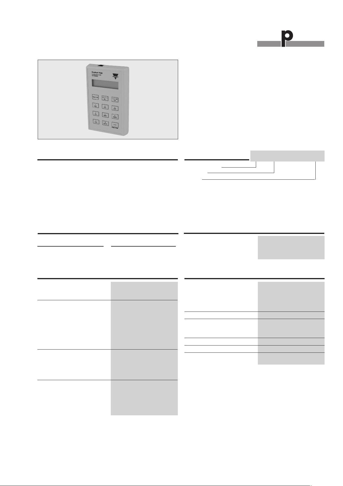
The Configurator has two cable slots.
One slot (RJ12 plug) for programming
the modules and the second slot (Jack
plug) is for testing /simulating directly
on the Dupline®bus.
There are two modes of operation for
the Carpark Configuration unit:
1. Configuration mode and
2. GTU mode.
In Configuration mode the unit can set
up the Dupline®Carpark Monitor
GP3482 9091 724 module or the
Dupline®Carpark Sensor GP6220
22xx 724 modules.
In GTU mode the unit can monitor the
Carpark units on the Dupline®bus.
Pressing the ”Read/ On” button powers
on the unit in either Configuration
mode or the GTU mode.
The modes are entered automatically
according to the connection used. If
the RJ connection is used, the Config-
uration mode will be entered. If the
jack connector is used, the GTU mode
will be entered.
When the Configurator is in GTU
mode, the tactile key “0 / 9” has the
function as “Mode/Enter”.
Explanat on of the symbols n the
d splay:
Marks an active channel
Marks an inactive channel
Indicate the use of a “Lane Detec-
tion Sensor”
Indicate the use of a “Calibration
address”
When the button 1 in a given group is
pushed for more than 1sec. the entire
group is activated.
Activated channels in a group
Fig.1
When a selection has to be made the
choices are marked as or
The current status/ selection from pre-
vious configuration is shown with
active notation or
Conf gurat on mode:
When connected to a Carpark sensor
or Carpark monitor through the RJ12
plug, Configuration mode is enabled.
When activating the unit, the text
“Configurator mode selected!” is
shown shortly in the display, followed
by the text “Config Unit begin?” When
pressing the “YES” button, the Config-
urator will start reading the connected
unit; “Reading Configuration” is shown
in the display while reading is in
progress.
If a Carpark sensor is connected, the
user can in “Mode selection” select
between “Normal” mode or “Lane”
mode.
Configuration of a sensor
Fig. 2
Normal mode: Standard sensor mode
detects the presence of a Car in the
parking space and light the red LED
and sends a signal out on the L1 bus.
When the parking space is empty the
LED will change to green and also
send a signal out on the L1 bus.
Lane mode: The sensor is placed in
the ceiling above the Lane and detects
the car before it enters into the parking
area. The Carpark system will count
down the total amount of free places
because of the moving Car, and show
the reduced amount on the monitor.
This is to prevent to many moving
Cars in a specific Carpark area.
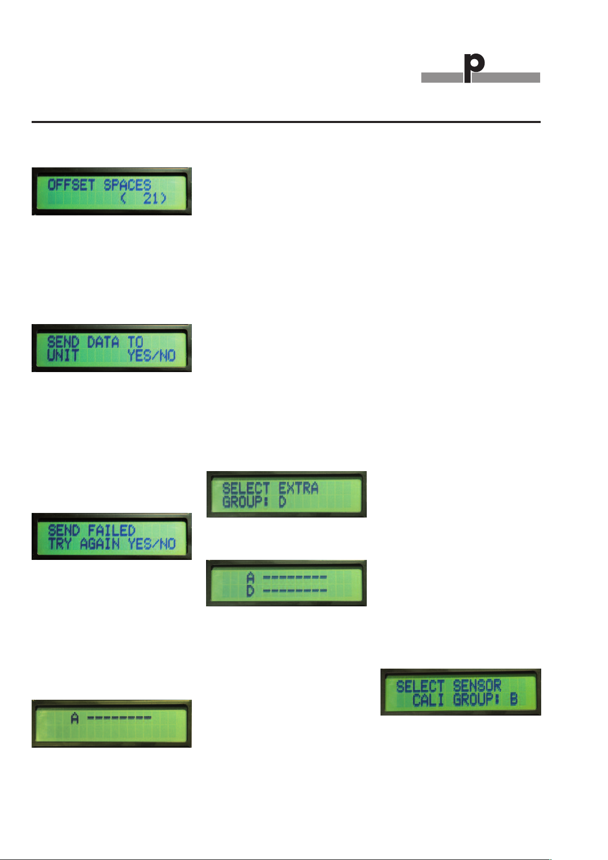
It is possible to see and change the
status and calibration channel for the
connected sensor.
See/Change status and calibration for
sensors
Fig. 3
If a monitor is selected, the user can in
“Mode selection” select between
“Master” mode or “Slave” mode.
Configuration of master/slave
Fig. 4
Slave mode:
A slave monitor is connected directly
to the sensors. Each slave monitor can
handle up to 127 sensors. The bus
where the sensors are connected is
named the L1 bus. The communica-
tion between the Slave monitors and
the Master monitor is named the L2
bus.
The maximum ID number is 480. See
Fig. 5. It means that it is possible to
install 480 L1 busses in a system.
In “Slave” mode the monitor can oper-
ate either in “Normal” mode or “Roof”
mode. See Fig. 6.
It is possible to change/see the “cali-
bration” address for the specific slave.
The calibration address in the Configu-
rator should be the same as the cali-
bration address for the sensors. See
fig.3 and 7.
Device ID for Slave mode
Fig. 5
Mode selection for Slave mode
Fig. 6
Calibration in Slave mode
Fig. 7
In “Normal operation Mode” the user
must know if a “Lane Detector Sensor”
is used on the L1 bus. If the user does
Mode of Operation
GP73800080

Du line
®
Fieldbus Installationbus
Specifications are subject to change without notice (12.12.2008) 3
Dupline®®is a registered trademark. A product of the CARLO GAVAZZI Group
GP73800080
Mode of Operation (cont.)
not use a “Lane Detector Sensor, dis-
able the address with two crosses
“XX” by pressing the tactile key “8”
If the “Lane Detector Sensor” is select-
ed it is possible to implement an “off
delay” of maximum120 Sec. See Fig.9.
When a Car moves under the “Lane
Detector Sensor” the Carpark system
count down the free number of parking
spaces with one, in the selected
amount of time. When the time runs
out, the Carpark system will go back
to the previous value until next time
the “Lane Detector Sensor” is activat-
ed.
Lane Detection in Slave mode
Fig. 8
Off Delay Lane in Slave mode
Fig.9
The Slave monitors are monitoring the
L1 bus with the maximum of 127 Sen-
sors. In “Units on Grp” (Fig. 10) the
user can see/select the channels for
each connected sensor. If one of the
numbers is replaced with or then
the address is occupied for e.g. “Lane
Detector Sensor” or “Calibration”.
The user can implement an “Offset
Space” (Fig.11) from 0 to 10 Cars on
each of the slave monitors. This allows
the system always to have maximum
10 spaces free for each of the slave
monitors. This is to prevent Car jam in
the parking area and offer the user
some extra free spaces.
Select/See channel for each connect-
ed sensor in Slave mode
Fig.10
Offset spaces in Slave mode
Fig. 11
In “Roof mode”, the slave monitor is
able to monitor up to 127 Sensors. At
the entrance of the roof, a sensor
detects each car passing and count
down the total numbers of free
spaces. The same happens at the exit,
but here it counts up the total numbers
of free spaces. The Input and the Out-
put sensor are specified with their
Dupline®channels. If, for some reason
there is a mismatch with the correct
number of free parking places, then it
is possible to reset the counter, when
the roof is empty (Fig. 13).
Roof Spaces in Slave mode
Fig. 12
In/Out channels and Reset channels in
Slave mode
Fig. 13
Master mode:
The GP3482 9091 724 monitor can
also be used in “Master mode”.
Select Master by press 1 (Fig.14).
Selection between Master and Slave
mode
Fig.14
If the user selects ”NO” in the indicator
mode, then the Master is making the
sync signal for the entire system. It is
only possible to have one Master in a
system. But several Master Indicators.
If “YES” is selected, then the Master is
working as an Master Indicator. That is
the same as the Master but the Master
Indicator cannot generate a sync sig-
nal.
Indicator in Master mode
Fig.15
In both modes the user must select if
the system is a “Small” or a “Large”
system. A small system has less than
240 Slave monitor connected. If a
large system is selected then there are
more than 240 slave monitors con-
nected. Maximum 480 slave monitors
can be connected to the system.
System size in Master mode
Fig. 16
By inserting the ID for the “Start”
address and “End” address, the Mas-
ter (or Master indicator) is able to mon-
itor a specific area in the Carpark sys-
tem. If e.g. 101 and 200 are selected
for the specific Master monitor, then it
is possible to see available parking
spaces in the area from Slave monitor
number 101 to Slave monitor number
200 and all the slave monitors in
between. Then it is possible to see 100
* 127 = 12700 parking places.
ID number in Master mode
Fig. 17
It is possible to select an “Offset
space” for the Master (or Master moni-
tor). The maximum number of “Offset”
is 9999.
The “Offset” is used to prevent Car
jam and to make a smooth parking

Du line
®
Fieldbus Installationbus
4Specifications are subject to change without notice (12.12.2008)
Dupline®®is a registered trademark. A product of the CARLO GAVAZZI Group
GP73800080
experience for the driver.
Offset spaces in Master mode
Fig. 18
When the settings are finished and
ready to transfer to the unit, the Con-
figurator will respond with “Send data
to unit”.
Send data to unit (Both sensor and
Master/Slave unit)
Fig. 19
If the transmission of some reason
fails, the Configurator will respond with
“Send failed Try again”.
The user must then find out what has
caused the failed transmission before
trying again. Please check cable or
battery in Configurator as possible
problems.
Message from the Configurator
Fig. 20
GTU mode:
When connecting to the Dupline®bus
through the Jack plug, GTU mode is
enabled. This is done by pressing the
“Read / On” button on the Configura-
tor when the Dupline®bus is connect-
ed. Then the display will show the
standard GTU “Mode 1”.
GTU mode 1
Fig. 21
The GTU have 4 modes.
- Mode 1 - Able to see one
Dupline®group
- Mode 2 - Able to two Dupline®
groups. * See note
- Latch - Able to latch any of the
128 Dupline®channels
- Calibration - Able to send the
calibrate sequence on any of
the 128 Dupline®channels
To change mode:
1. Press « Mode/Enter »
2. Shift between mode options by
pressing either « ←» Or « →».
3. Select mode by pressing « Mode/
Enter ».
* How to select the extra group in
mode 2
1.Select mode 2
2.Select the Dupline®letter (A-P)
by pressing the specific tactile key
a. Example: We want “D” as
the second Dupline®group.
b. Press tactile key “2” one
time and the letter “D” will
appear as second group
Mode 2 selected
Fig. 22
Mode 2 Extra group added
Fig. 23
D g tal 1 group
Once connected to the Dupline®, the
display shows the status of channel
group A. Active channels are indicated
by their numbers. Pressing «1», «2» ...
«8» will activate the corresponding
Dupline®channel in the selected chan-
nel group.
Pressing « ←» or « →» changes the
channel group showing the display.
D g tal 2 groups
When the mode "Digital 2 groups" is
selected, the user may select an addi-
tional channel group for permanent
monitoring on the bottom line of the
display. The channel status of the two
selected groups can now be moni-
tored, but changing the channel status
through the keys «1» ... «8» only
affects the channels displayed in the
upper row of the display. Even so,
pressing the « ←» or « →» key only
changes the channel group in the
upper row of the display.
Ed t Tx-latch
In this mode it is possible to "latch"
the activation of one or more channels.
This means that the GTU will continue
transmitting on the channel(s) even
though the corresponding transmis-
sion button is released.
To cancel the transmission on a chan-
nel, press the corresponding transmis-
sion button again.
The latched transmission will continue
even if the channel group or mode is
changed. In order to change the status
of a latched transmission, it is neces-
sary to re-enter the "Edit Tx-latch"
mode.
All the latched channels are reset to
normal Dupline®operation whenever
the GTU becomes disconnected from
the Dupline®.
Sensor Cal brat on
The Sensor Calibration function is car-
ried out as a sequence of steps. The
function controls one channel on the
Dupline®bus.
Select calibration mode.
1. Enter this function and select the
decided Dupline®group:
“SELECT SENSOR CALI GROUP: X”
(X = Group number).
Press « Mode/Enter » when the want-
ed group is selected.
Select calibration group
Fig. 24
2. When Group is selected the channel
within the group must be selected.
“SELECT SENSOR CALI CHANNEL:
XY”
Mode of Operation (cont.)

Du line
®
Fieldbus Installationbus
Specifications are subject to change without notice (12.12.2008) 5
Dupline®is a registered trademark. A product of the CARLO GAVAZZI Group
Additional Information
Scope of supply:
1 x Conf./Test unit GP7380 0080
1 x Programmer cable GAP CAB
1 x Test cable GTU8 GRIP CAB
Mode of Operation
(X = Group number,
Y = Channel in-group X).
Press « Mode/Enter » when the want-
ed channel is selected.
Select calibration channel
Fig. 25
3. When the channel has been select-
ed, an intermediate state is entered:
“ PRESS ENTER TO CALIBRATE!”
Press « Mode/Enter » to start Calibrat-
ing.
Start calibration
Fig. 26
4. When « Mode/Enter » is pressed the
calibration is started and a progress
bar is shown in the display:
“0%: ************************: 100%
Calibration in progress
Fig. 27
Don’t press anything the GTU will
change state automatically.
5. When calibration is finished the fol-
lowing will be shown in the display:
“FINISHED! PRESS « Mode/Enter » TO
EXIT”
Pressing the « Mode/Enter » button is
the only way to restart calibration or
entering a new mode of operation!
Warn ng:
Do not plug in the Jack connector
when it is connected to Dupline®and
the configuration unit is ON. This will
cause a short-circuit of the two wires.
Note:
If the Dupline®carrier is missing, the
display will come up with the text
shown in Fig. 28
After a few sec. the display will turn
off, if nothing has been done or any
buttons has been pressed
Config unit (Both Sensors, Master and
Slave units)
Fig. 28
Low Battery
If, when activating the Configuration
and GTU Unit, “ * LOW BATTERY * ” is
showed in the display, it is time for
changing the battery. The unit will con-
tinue to work, but it is recommended
that the battery is changed. The bat-
tery is changed by dismounting the 4
screws on the back of the unit and
removing the back cover. After that,
take out the PCB, change the 9V bat-
tery and then reassemble the unit.
Table of contents
Popular Test Equipment manuals by other brands

Hakko Electronics
Hakko Electronics FG-470 instruction manual

Alps Electric
Alps Electric FlexPitch Operator's manual

Seaward
Seaward PrimeTest 125 EL Operating instruction

Gossen MetraWatt
Gossen MetraWatt SECULIFE ST PRO manual

Steinberg Systems
Steinberg Systems SBS-LSG-001 user manual

Wiltron
Wiltron 67 B Series Maintenance manual