Profimess SW-07 Series User manual

Profimess GmbH
Twischlehe 5
D-27580 Bremerhaven
Operatin instructions
SW-07 (1/2“)
Varible Area Flowmeter and Switch
Status: February 2015
Technical modifications reserved

20.02.2015
2
Profimess GmbH
Twischlehe 5
27570 Bremerhaven
Germany
Telephone: + 9 71 98 2 - 151
Fax: + 9 71 98 2 - 152
email: info@profimess.de
Internet: www.profimess.com

These instructions facilitate the safe
and efficient handling of a flow monitor
(referred to as "device" in the fol-
lowing). The instructions are an inte-
gral part of the device and must be
kept within easy reach for the per-
sonnel in the immediate vicinity of the
device at all times. Personnel must
carefully read and understand these
instructions before commencing all
work. The basic requirement for safe
work is adherence to all safety and
handling instructions stipulated in
these instructions. The local accident-
prevention regulations and general
safety standards and regulations for
the field of application of the device
also apply. Illustrations in these
instructions are provided to aid general
understanding and might deviate from
the actual model. No claims can be
derived from any such differences.
Limitations of liability
All details and instructions in this
manual have been compiled under
consideration of the valid standards
and regulations, the current state-of-
technology and our many years of
knowledge and experience. The manu-
facturer does not accept any liability
arising from:
nnon-observance of any details in
these instructions
nimproper use of the device, or use
that is not in accordance with
these instructions
nuse of non-trained personnel
nunauthorized retrofitting or tech-
nical changes that have not been
authorized by the manufacturer
nuse of non-approved spare parts
The duties and obligations agreed
upon in the delivery contract apply in
full, as well as the general terms and
conditions, the terms of delivery by the
manufacturer and the valid legal regu-
lations applicable at the conclusion of
the contract.
Copyright
These operating instructions are pro-
tected by copyright.
Except for internal purposes, transfer
of these instructions to third-parties,
copying them in any way
– even in part – as well as dissemina-
tion and/or communication of their con-
tent is forbidden without prior written
authorization from PROFIMESS
("manufacturer"). Violations
are subject to claims for indemnifica-
tion. The manufacturer reserves the
right to assert additional claims.
Copyright is the property of the manu-
facturer.
Supplemental instructions
20.02.2015 3

Table of contents
1 Overview...................................................................................................... 7
1.1 Short description.................................................................................. 7
1.2 Warranty and guarantee provisions..................................................... 7
1.3 Customer service................................................................................. 7
2 Safety........................................................................................................... 8
2.1 Explanation of symbols........................................................................ 8
2.2 Correct use in accordance with these instructions............................. 10
2.3 Special precautions............................................................................ 11
2.3.1 Hazards from electrical current....................................................... 11
2.3.2 Mechanical hazards........................................................................ 12
2.3.3 Hazards from high or low temperatures.......................................... 13
2.3. Radiation hazards........................................................................... 13
2.3.5 Hazards caused by media............................................................... 1
2. Personnel requirements..................................................................... 1
2.5 Personal safety equipment................................................................. 15
2.6 Protective systems............................................................................. 16
2.7 Spare parts......................................................................................... 16
2.8 Environmental protection................................................................... 17
2.9 Responsibility of the owner................................................................ 17
3 esign and function................................................................................. 20
3.1 Overview............................................................................................ 20
3.2 Device description.............................................................................. 20
3.3 Component description...................................................................... 21
4 Transport, packaging and storage.......................................................... 22
.1 Safety instructions for transport......................................................... 22
.2 Transport inspection........................................................................... 22
.3 Packaging.......................................................................................... 22
. Symbols on the shipping box............................................................. 23
.5 Storage............................................................................................... 23
5 Installation and initial startup operation................................................ 25
5.1 Safety................................................................................................. 25
Table of contents
20.02.2015

5.2 Requirements at the place of installation........................................... 25
5.3 reparatory work.................................................................................. 26
5. Installation in the pipe system............................................................ 29
5.5 Initial startup....................................................................................... 33
5.6 Electrical connection.......................................................................... 3
5.6.1 Plug connector DIN 3650.............................................................. 35
5.6.2 Plug connector M12x1.................................................................... 36
5.6.3 Cable............................................................................................... 37
5.6. Degree of protection (IP-Code)....................................................... 37
5.7 Grounding the device......................................................................... 37
5.8 Plug connection.................................................................................. 38
5.9 Contact protection measures............................................................. 1
6 Operation................................................................................................... 43
6.1 Setting the switch point...................................................................... 3
6.2 Checking the flow............................................................................... 5
7 Troubleshooting....................................................................................... 47
7.1 Safety................................................................................................. 7
7.2 Troubleshooting guide........................................................................ 9
8 Maintenance.............................................................................................. 51
8.1 Safety................................................................................................. 51
8.2 Maintenance plan............................................................................... 51
8.3 Removal from the pipe system........................................................... 52
8. Disassembly....................................................................................... 53
8.5 Maintenance....................................................................................... 57
8.5.1 Cleaning.......................................................................................... 57
8.5.2 Parts replacement........................................................................... 58
8.5.3 Assembly......................................................................................... 58
8.5. Switch contact replacement............................................................ 65
8.6 Measures to be taken after maintenance work.................................. 67
9 isassembly and disposal....................................................................... 68
9.1 Safety................................................................................................. 68
9.2 Disassembly....................................................................................... 68
Table of contents
20.02.2015 5

9.3 Return Materials................................................................................. 68
9.3.1 Return Materials Authorization........................................................ 68
9. Disposal............................................................................................. 69
10 Technical data........................................................................................... 70
10.1 Device data plate............................................................................. 70
10.2 Switch contact data plate................................................................. 70
10.3 Dimension sheet.............................................................................. 71
10. General specifications...................................................................... 72
10.5 Electrical specifications.................................................................... 72
10.6 Measuring ranges............................................................................ 7
10.6.1 Standard measuring ranges.......................................................... 7
10.7 Operating data................................................................................. 7
11 Appendix................................................................................................... 75
11.1 Tightening torque............................................................................. 75
11.2 Replacement parts........................................................................... 75
11.3 Tools................................................................................................ 77
11. Sealant............................................................................................. 77
11.5 Lubricants......................................................................................... 78
Table of contents
20.02.20156

1 Overview
1.1 Short description
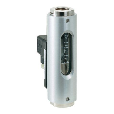
Fig. 1: SW-07 flow monitor
01 Sight glass with measuring scale
02 Switch contact with female socket
or sealed-in cable
The flow monitor SW-07 monitors the
continuous flow of liquids. It is
designed for installation in pipe sys-
tems.
A float inside the device is moved by
the medium flowing through it. The cur-
rent rate of flow can be read-off on the
measuring scale of the sight glass. The
top edge of the float is the read-off
point.
External measuring devices can be
connected at the socket.
1.2 Warranty and guar-
antee provisions
Warranty and guarantee provisions are
contained in the general terms and
conditions of the manufacturer.
1.3 Customer service
For technical information, please con-
tact our customer service department
(for contact details, see Page 2).
Furthermore, our staff is always inter-
ested in receiving new information and
experiences gained from application of
the device, which might be useful in
improving our products.
Overview
Customer service
20.02.2015 7

2 Safety
This chapter provides an overview of
important safety aspects required for
optimum protection of personnel as
well as for safe installation and safe
operation of the device.
Non-observance of the handling and
safety instructions listed in this manual
may result in hazardous/dangerous sit-
uations and in damage to property.
2.1 Explanation of sym-
bols
Safety instructions
Safety instructions in this manual are
marked by symbols. The safety instruc-
tions are preceded by signal words that
indicate the level of danger/hazard.
To prevent accidents or injuries to per-
sons as well as damage to property,
always observe the safety instructions
and proceed carefully.
ANGER!
This combination of symbol and
signal word indicates an imme-
diate, dangerous situation that
results in death or serious injuries
if it is not avoided.
WARNING!
This combination of symbol and
signal word indicates a possibly
dangerous situation that might
result in death or serious injury if it
is not avoided.
Safety
Explanation of symbols
20.02.20158

CAUTION!
This combination of symbol and
signal word indicates a possibly
dangerous situation that might
result in minor or slight injuries if it
is not avoided.
NOTICE!
This combination of symbol and
signal word indicates a possibly
dangerous situation that might
result in damage to property and to
the environment if it is not avoided.
Tips and recommendations
This symbol emphasizes useful
tips and re ommendations as well
as information for effi ient and
failure-free operation.
Signs used in these instructions
The following signs and highlighting
are used in these instructions to iden-
tify handling instructions, the descrip-
tion of results, lists/enumerations, ref-
erences and other elements:
Designates step-by-step han-
dling instructions
ðDesignates a state or an
automatic sequence as a
result of a specific operating
step
nDesignates randomly ordered enu-
merations and list entries
Ä “Signs used in these instru tions”
on page 9, designates references to
chapters in these instructions
Safety
Explanation of symbols
20.02.2015 9

2.2 Correct use in
accordance with
these instructions
The device is designed and con-
structed exclusively for the intended
use described herein.
Correct use in non-hazard areas
The flow monitor serves exclusively
to monitor the continuous flow of liq-
uids within a temperature range of
-20 °C to 120 °C (optional: 160 °C) at
a maximum operating pressure of 16
bar.
Correct use in explosion-hazard
zones
For employment in explosion-hazard
zones, changed conditions apply for
the intended use.
The intended use in explosion-hazard
zones is described in the Operating
Instructions "SW-07 (1/2“) Module ATEX".
Intended use in explosion-hazard
zones includes the observance of all
specifications in these Operating
Instructions, as well as those for
"SW-07 (1/2“) Module ATEX ".
Any additional or different application,
above and beyond the correct use in
accordance with these instructions, is
deemed as incorrect use.
WARNING!
anger due to incorrect use!
– Use the flow monitor only
within the stipulated perform-
ance limits
– Do not subject the flow mon-
itor to severe temperature fluc-
tuations
– Do not use the flow monitor
with quick-acting valves
– Do not use the flow monitor
with solenoid valves
– Do not subject the flow mon-
itor to vibrations
– Do not subject the flow mon-
itor to pressure surges
– Do not use the flow monitor
with media containing solids or
abrasives
– Only use the flow monitor with
media previously approved by
the manufacturer
– Do not use the flow monitor as
the sole monitoring device to
prevent dangerous conditions
– Do not install the flow monitor
as a load bearing part within a
pipeline system
– The flow monitor with sight
glass must be installed in such
a way as to preclude damage
to the sight glass by outside
force. If necessary, install an
appropriate impact protection
device
– Incorrect use of the flow mon-
itor may result in dangerous
situations
Safety
Correct use in accordance with these instructions
20.02.201510

All claims for damages due to incorrect
use are excluded.
2.3 Special precautions
The following section lists residual
risks that might arise from the device.
To reduce health risks and prevent
dangerous situations, observe the
safety instructions listed here as well
as the safety instructions in the other
chapters of these operating instruc-
tions.
ANGER!
Employment of the device in
explosion-hazard zones
requires the observance of the
Operating Instructions for
SW-07 (1/2“) Module ATEX"
includingall hazard statements
And warnings, therein.
These operating instru tions
annot over all on eivable dan-
gers be ause many dangers arise,
not from the devi e itself, but from
the respe tive media flowing
through it. Always observe the
appropriate safety data sheets
when using hazardous media!
2.3.1 Hazards from elec-
trical current
Electrical current
ANGER!
anger to life from electrical
current!
There is an immediate risk to life
from electrocution on touching live
parts. Damaged electrical insula-
tion or components can be
extremely dangerous.
– Only qualified electricians
shall work on the electrical
system.
– If the insulation is damaged
then immediately switch off
and have repairs carried out.
– Before commencing work on
live parts of the electrical sys-
tems and operating equip-
ment, disconnect the equip-
ment and ensure that it
remains disconnected for the
duration of the work. Observe
these 5 safety rules when
doing so:
– Isolate (disconnect)
– Secure against switching
back on
– Check for absence of
voltage
– Ground and short
– Cover or cordon off other
live parts in the vicinity
Safety
Special precautions > Hazards from electrical current
20.02.2015 11

– Never bridge fuses or put
them out of operation. Always
observe the correct current
ratings when replacing fuses
– Keep moisture away from live
parts. This can result in short-
circuit
2.3.2 Mechanical hazards
WARNING!
Risk of injury from glass
breakage!
The sight glass in the flow monitor
can burst due to excessive tem-
perature or pressure. There is a
risk of injury from flying glass
splinters and escaping media.
– Keep within the stipulated
operating conditions
– Wear personal protective
equipment
– Avoid severe temperature fluc-
tuations
– Avoid pressure surges
CAUTION!
Risk of injury on sharp edges
and pointed corners!
Sharp edges and pointed corners
can cause abrasions and skin
cuts.
– Proceed with caution when
working near sharp edges and
pointed corners.
– If in doubt, wear protective
gloves.
Safety
Special precautions > Mechanical hazards
20.02.201512

2.3.3 Hazards from high
or low temperatures
Hot or cold surfaces
WARNING!
Risk of injury from hot or cold
surfaces!
Surfaces of components may heat
up/cool down dramatically due to
the media flowing through them.
Skin contact with hot or cold sur-
faces causes severe skin burning/
freezing.
– Always wear temperature-
resistant protective work
clothing and protective gloves
when working near hot/cold
surfaces
– Before commencing any work,
make sure that all surfaces
have been cooled down or
warmed up to ambient temper-
ature
2.3.4 Radiation hazards
Strong magnetic fields
WARNING!
anger to life from strong mag-
netic fields!
Strong magnetic fields may cause
severe injuries or even be fatal, as
well as cause considerable
damage to property.
– Persons with pacemakers
must not be located in the
vicinity of the device. This
could impair the function of the
pacemaker
– Persons with metal implants
must not be located in the
vicinity of the device. Implants
can heat up or be attracted
magnetically
– Keep ferromagnetic materials
and electromagnets away
from the magnetic source.
These materials could be
attracted and fly through the
room, thereby injuring or even
killing persons. Minimum
clearance: 3 m
– Remove and put away metal
objects before maintenance
work (jewelry, watches, writing
implements, etc.)
– Do not place any electronic
devices within the vicinity of
the magnetic source. These
could be damaged
Safety
Special precautions > Radiation hazards
20.02.2015 13

– Do not place any electronic
storage media, credit cards,
etc. within the vicinity of the
magnetic source. Data could
be deleted
2.3.5 Hazards caused by
media
Hazardous media
WARNING!
Risk of injury from hazardous
media!
If the flow monitor is used for toxic,
corrosive or very hot/cold media
then there is a risk of serious injury
if the media escapes.
– Observe details in the safety
data sheet of the media
– Comply with the safety, acci-
dent prevention and environ-
mental protection regulations
appropriate to the media used
– Wear personal protective
equipment in accordance with
the safety data sheet
2.4 Personnel require-
ments
WARNING!
Risk of injury due to use of
insufficiently trained and quali-
fied personnel!
If unqualified personnel work on
the device or are located within its
hazard zone, dangers arise which
may result in serious injuries and
considerable damage to property.
– All work must be performed by
qualified personnel only.
– Keep unqualified personnel
away from hazard zones.
Authorized personnel is to be restricted
to those persons who can be expected
to carry out their work reliably. Persons
whose ability to respond is influenced,
e.g. by drugs, alcohol or medication,
are not authorized.
Observe the age and occupational reg-
ulations at the site when choosing per-
sonnel.
Safety
Personnel requirements
20.02.20151

The following lists the personnel quali-
fications for the various areas of
activity:
Qualified electrician
Due to specialized training, knowledge
and experience as well as knowledge
of the relevant standards and regula-
tions, the qualified electrician is able to
independently perform work on the
electrical systems as well as to detect
and avoid possible risks and dangers.
Additionally, the electrician must pro-
vide proof of his/her professional quali-
fication that certifies his/her ability to
perform work on electrical systems.
The qualified electrician must fulfill the
requirements contained in the valid
legal accident-prevention regulations.
Qualified personnel
Due to their specialized training, knowl-
edge and experience as well as their
knowledge of the relevant standards
and regulations, qualified personnel
are able to independently carry out the
work assigned to them as well as to
detect and avoid possible risks and
dangers.
2.5 Personal safety
equipment
Personal safety equipment is used to
protect personnel from hazards/dan-
gers that might impair their safety or
health during work.
When performing the various tasks at,
and with the device, personnel must
wear personal safety equipment. Spe-
cial reference is made of this in the
individual chapters within these Oper-
ating Instructions. The following pro-
vides a description of the personal
safety equipment:
nAlways put on the appropriate per-
sonal safety equipment required in
the various chapters of these
Operating Instructions before com-
mencing work.
nComply with the personal safety
equipment instructions posted
within the work area.
escription of personal safety
equipment
Goggles
The goggles are used to protect the
eyes from flying debris and splashing
fluid.
Protective gloves
Safety
Personal safety equipment
20.02.2015 15

Protective gloves protect the hands
from friction, burns, grazing, abrasion,
surface cuts or deeper injuries, as well
as from direct contact with hot or cold
surfaces.
With hazardous media, the protec-
tive equipment specified in the
Safety ata Sheet of the medium
must be worn. In addition, the speci-
fications of the system operator
must be followed. If no protective
equipment is specified, suitable pro-
tective gloves and goggles must be
worn.
The protective equipment is used to
protect against hazardous media leaks
and hazardous media residue in the
device.
2.6 Protective systems
Integration within an emergency-
stop concept is required
The device is designed for use as a
part of a machine or system. It does
not have its own controller and does
not have an autonomous emergency-
stop function.
Before starting up the device, install
the emergency-stop equipment and
incorporate it into the safety chain of
the machine or system.
Connect the emergency-stop equip-
ment so that if there is an interruption
in the power supply or in the activation
of the power supply after an interrup-
tion, dangerous situations are excluded
for persons and valuables.
The emergency-stop equipment must
always be freely accessible.
2.7 Spare parts
WARNING!
Risk of injury due to use of
incorrect spare parts!
Use of incorrect or faulty spare
parts may result in dangers to per-
sonnel as well as damages, mal-
functions or total failure.
– Only use original spare parts
from the manufacturer or
approved by the manufacturer.
– Always contact the manufac-
turer in case of doubt.
Safety
Spare parts
20.02.201516

Always purchase spare parts from an
authorized dealer or directly from the
manufacturer (For contact details, see
Page 2).
The spare parts list is in the annex.
2.8 Environmental pro-
tection
NOTICE!
Risk to the environment due to
improper handling of environ-
mentally hazardous substances!
Serious environmental damage
can result if substances harmful to
the environment are handled incor-
rectly, especially if they are dis-
posed of improperly.
– Always observe the instruc-
tions listed below on the han-
dling and disposal of sub-
stances harmful to the
environment.
– If harmful substances are
released into the environment,
take immediate countermeas-
ures. If there is doubt, contact
the local authorities, inform
them of the damage and
request information on suit-
able countermeasures to be
taken.
Cleaning fluids
Solvent-based cleaning fluids contain
toxic substances. They must never be
released into the environment and
must be disposed of by a waste man-
agement company.
Lubricants
Lubricants such as greases and oils
contain toxic substances. They must
never be released into the environment
and must be disposed of by a waste
management company.
2.9 Responsibility of the
owner
Owner
The owner is the person who operates
the device himself for business or com-
mercial purposes or who cedes such
use/application to a third-party and
who, during operation of the device,
has full legal product stewardship for
protection of the user, the personnel or
third-parties.
uties of the owner
The device is used in the commercial
sector. The owner of the device is
therefore subject to legal obligations
pertaining to work safety.
Safety
Responsibility of the owner
20.02.2015 17

In addition to the safety instructions
contained in these Operating Instruc-
tions, the safety, accident prevention
and environmental protection regula-
tions applicable to the field of applica-
tion of the device must be observed.
In particular, this includes:
nThe owner must inform himself
regarding the valid health and
safety regulations and must carry
out a risk assessment to addition-
ally determine the risks resulting
from the special work conditions
arising at the location at which the
device is used, especially in regard
to the media used. He must then
implement these within Operating
Instructions for use of the device.
nThe "Occupational Health and
Safety Act" of 1970 stipulates that
it is the duty of the owner to pro-
vide a safe workplace. He must
hereby ensure that the device is
operated and maintained com-
pliant to valid commercial, indus-
trial, local, federal and state laws,
standards and regulations.
nAppropriate to the working condi-
tions and the media used, the
owner must affix signs within the
working area that inform the user
of the hazards and dangers
present.
nDuring the entire period of use of
the device, the owner must check
periodically to ensure that the
Operating Instructions correspond
to the current state of regulations,
and he must make adjustments as
necessary.
nThe owner must clearly regulate
and determine responsibilities for
installation, operation, trouble-
shooting, maintenance and
cleaning.
nThe owner must fit/retrofit suitable
safety equipment within the com-
plete plant/system.
nThe owner must ensure that all
staff/personnel have thoroughly
read and understand these instruc-
tions before handling the device.
Additionally, he must train the per-
sonnel at regular intervals and
warn them of dangers.
nThe owner must provide the per-
sonnel with the required safety
equipment and must instruct them
that its wear is mandatory.
Additionally, the owner is responsible
for ensuring that the device is always
kept in a technically perfect condition.
The following therefore applies:
nThe owner must implement suit-
able safety measures, appropriate
to the media used.
nDifferent media have different
severities of influence on the
soiling and wear of/to the device.
The owner must set suitable main-
tenance intervals, depending on
the media flowing through the
device.
Safety
Responsibility of the owner
20.02.201518

nThe owner must ensure that the
maintenance intervals described in
these Operating Instructions are
adhered to at all times.
nThe owner must ensure that the
device is completely free of any
residual media before disposal.
Remains of corrosive or toxic
materials must be neutralized.
Safety
Responsibility of the owner
20.02.2015 19

3 esign and function
3.1 Overview
Fig. 2: Front view
01 Process connection (outlet)
02 Device housing
03 Spring
0 Sight glass with measuring scale
05 Float containing magnets
06 Process connection (inlet)
07 Switch housing with female socket
or switch housing with cable
3.2 evice description
SW-07 flow meters work according to
the functional principle of the variable
area flowmeter. The flow monitor is
installed into a pipe system and meas-
ures the flow-rate of the medium
flowing through the pipe system.
A float inside the flow monitor is moved
by the flowing medium. A magnetic
field is generated by the magnets
inside the float. The position of the float
is detected by the switch contact. In
addition to electrical control through
the Reed-contact (switch contact), the
current flow rate can also be read-off
on the measuring scale on the sight
glass.
SW-07 flow monitors are used in, e.g.
lubricating circuits: The flow monitor
monitors the volumetric flow of the
lubricating media to ensure it is high
enough to ensure sufficient lubrication.
If the flow through the flow monitor
drops below the threshold preset by
the operator, the switch contact
switches (change-over contact) or
closes the contact (normally open con-
tact).
esign and function
Device description
20.02.201520
This manual suits for next models
4
Table of contents
Other Profimess Measuring Instrument manuals


