Proflex G9 User manual

ProFlex®G9
SERVICE MANUAL Your System Configuration
Temperature Controls
Microprocessor - 4th Gen
4 Hose / 4 Gun
Single Motor / Pump
Voltage Requirements
220 VAC, Single Phase, 40 A
07/08/20 Rev A
1723 W. Hamlin Rd | Rochester Hills, MI 48309
248.853.2011 | www.hotmelt-tech.com
No One Puts It Together Like HMT®

Intended Use
Benchmark® and ProFlex® adhesive melters and components are designed to melt
and pump thermoplastic hot melt adhesives and sealants. Any other use is considered
to be unintended. Hot Melt Technologies (HMT) will not be liable for personal
injury or property damage resulting from unintended use. Intended use includes
the observance of HMT safety instructions. HMT recommends obtaining detailed
information on the hot melt materials being used.
The product is only intended for use in industrial applications and may
only be used to melt and pump thermoplastic hot melt adhesives
(e.g. EVA, PSA, APO, Polyamid).
The product may only be installed, assembled, commissioned, operated,
maintained, repaired, de-commissioned and disposed of by trained
personnel.
The product may only be operated with compatible original components
and original accessories from Hot Melt Technologies Inc.
The product is to be used exclusively for the purpose described herein
and within the limits defined in this document. The product must not
be modified with respect to its structure or its safety features without
the written consent of Hot Melt Technologies. No changes to the
software or hardware of HMT products are permitted. Only use
original spare parts, original accessories or standard parts that
have been approved by HMT.
The instructions are part of this product. No applications other than those described
in the instructions are permitted.
Improper Use
Examples of misuse of the product include:
Melting and pumping of unsuitable adhesives
(e.g. PUR-Polyurethane hot melt adhesives)
In defective condition
With electrical cabinet open
With the tank lid open
Melting and pumping materials which, when under vacuum or pressure,
can pose a health hazard or endanger safety in the workplace
(e.g. solvents, explosive or highly flammable materials)
Cleaning the product with highly flammable materials (e.g. solvents)
Use in environments that require cleaning of the product with jets or
sprays of water
Processing of food
Residual Risks
In the design of the Benchmark and ProFlex systems, every measure was taken
to protect personnel from potential danger. However, some residual risks can
not be avoided:
Risk of burns from hot material
Risk of burns when filling the tank, from the tank lid, and from the hose
and gun exposed metal surfaces.
Risk of burns when conducting maintenance and repair work for which
the melter or components must be heated up.
Material fumes may be hazardous. Always avoid direct inhalation.
Product Introduction
©2020 Hot Melt Technologies, Inc
Table of Contents ......................................................................................................... 3
Safety & Set Up ..........................................................................................................4-5
Operating Instructions................................................................................................6-8
Front Panel Controls.................................................................................................6
Temperature and System Controls...........................................................................7
Front Panel ...............................................................................................................8
Electrical ...................................................................................................................9-10
Fuse & Relay Chart.................................................................................................... 9
Schematic................................................................................................................ 10
Warranty Information .................................................................................................11
©2020 Hot Melt Technologies, Inc Page 3
Proflex®G9-4

Page 4 ©2020 Hot Melt Technologies, Inc
Proflex®G9-4
Safety & Set Up
WARNING
Do not allow the pump motor to stall. A prolonged stall may damage
the motor and other components.
Do not connect or disconnect electrical connectors, or remove
components, with the power on. This will prevent arcing of electrical
contacts and possible failure of components.
Always close and secure the control panel access cover to protect
internal electrical components.
Always operate the system with the tank full and lid on.
Prior to dismantling, assembly, or adjustment of certain service parts
(hose/gun fittings, pump assemblies, etc.), the part(s) being serviced
should be preheated to reduce the chance of stripping threads or
ruining components.
Working on or around hot melt adhesives and equipment can cause
severe burns.
Use eye protection, gloves and protective clothing while operating
and/or servicing hot melt equipment.
Before installing any hot melt equipment, determine proper electrical
requirements per all applicable codes.
At Hot Melt Technologies, we pay special attention to the needs of
operators and service personnel when designing equipment, but
molten hot melt adhesives are dangerous and can cause severe burns.
Extreme care must be exercised to insure personnel safety.
Fire, explosion, personal injury, property, and/or equipment damage
can result if the material(s) used in or around any hot melt adhesive
supply unit are toxic, heat, or re sensitive. Always read the
manufacturer’s recommended use guidelines.
All HMT units are equipped with over temperature protection as
a necessary safety device. Run-away heating can cause hot melt
materials to exceed their ashpoint.
STOP
STOP
If incorrectly used, this machine can cause severe injury.
Those who use and maintain the machine should be trained in
its proper use, warned of its dangers, and should read the entire
manual before attempting to set up, operate, adjust or service
the machine.
©2020 Hot Melt Technologies, Inc Page 5
Proflex®G9-4
Safety & Set Up
08/01/19 Rev A
Before Using Your Hot Melt System
It is your responsibility and obligation to
make sure your system:
Has been properly installed off the floor and
on a steady, level work surface away from
combustible materials.
Has been located in such a way that the controls
are away from the operator and that the control
panel is securely closed at all times.
Is the right capacity system for the intended use.
Is connected to the proper power supply.
(See Below).
Is only used to do what a hot melt system is
designed to do.
Is not used by anyone unable to operate
it properly.
Is used in an area where the room temperature
does not fall below 65°F.
Is used in an area which is free from blowing air
caused by cooling fans, open doors or windows.
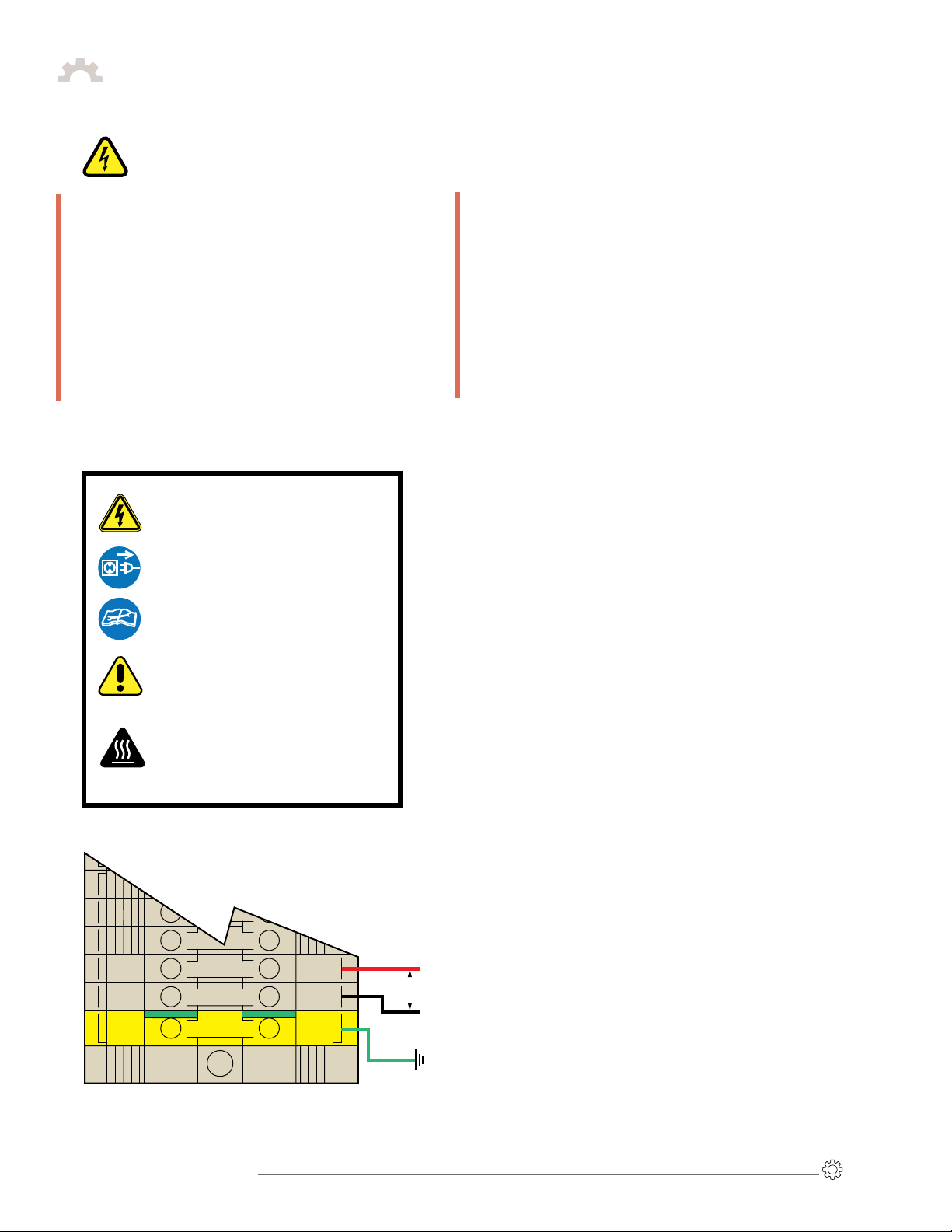
Basic Electrical Power Connections
For 220 VAC Operation
A fused 40 A 220 VAC electrical supply is required.
Performance problems will occur with voltages
less than 208 VAC or greater than 240 VAC.
Total amperage draw will depend on the final
system configuration; number of hoses & length,
guns, accessories, etc.
Do not allow the system to share the same circuit
with other electrical items. A dedicated supply is
recommended.
Do not use an extension cord.
If you change the configuration of your system in
any way that may affect the electrical
requirements (ex. add a gun, longer hose,
automate, etc.) call HMT Technical Service &
Support at 248-853-2011 for assistance.
L2
L1
G
L2
L1
G
L2 (R)
L1 (B)
G (G)
220 VAC Single Phase
Control Box
Protect your hot melt equipment by installing a
GFEP (Ground Fault Equipment Protector) device
in your distribution panel.
HMT recommends that hot melt systems be
protected from unintended line-to-ground
currents by installing an appropriate ground fault
equipment protection (GFEP) device. Contact
HMT Technical Service & Support or a qualied
electrical contractor for more information. When
installing a GFEP device always comply with local
electrical codes.
Prevent Serious
Equipment Damage
LEGEND: SAFETY SYMBOLS
Electric Shock Hazard: Line Voltage
Present with Machine Power Off. Risk
of electrical Shock or Burn
Disconnect Power Before Servicing
Consult Service Manual
Warning/Caution: Used to draw
attention to Hot Surface Warnings,
Over Temp Alarms, Hose Routing
Practices, and other safety notifications.
Hot Surface: Surface and surrounding
area may be hot. Exercise extreme
caution and utilize proper Personal
Protective Equipment (PPE).

Page 6 ©2020 Hot Melt Technologies, Inc
Proflex®G9-4
Operating Instructions
Front Panel Controls
Temperature Display
000
Temperature
Set-Back Control
20-70%
G-9
#3
#4
#3
#4
220 Volt
340-143 Rev:D
000
2
11
13
15
3
8
1
10
®
12
7
4
6
5
9
14
1
2
3
4
7
5
6
Main Power Switch: Turns the system “ON” or “OFF.“
Service Clock: Displays the number of hours that the system
has been ON.
Audible Over Temp Alarm: Sounds when a zone is in
Over Temp. (See #6).
High Limit: Limits the Set Point for any zone; adjustable
between 250°F and 475°F.
To Adjust the High Limit: Turn the system off. Press and hold
down the High Limit button and turn the Power Switch ON.
The display will show the current High Limit.
Release the High Limit button and use the Arrow Keys to
adjust High Limit Up or Down. Turn the Main Power Switch
OFF then ON again. All zones will default to the new High
Limit and must be reset.
Arrow keys and Set Mode LED: See # 4, 11, 12, 13, and 16
for usage.
Zone Status:
Sensor Fault: The LED will light and indicate that no RTD
sensor input is present in the selected zone.
Over Temp: The LED will light and affected zone LED will blink
if temperature exceeds High Limit by 25°F (14°C). The audible
Over Temp Alarm will also sound.
Ready: The LED will light when the zone temperature rises
to its respective set point.
Low Temp: The LED will light when the zone temperature
is below its respective set point. It is normal for all zones
to indicate “Low Temp” as the system heats from a
cold start-up.
Temperature Display: Displays Set or Actual temperatures of
heated zones (e.g. Tank, Hose, Gun, Grid) as well as programmed
values of other features (e.g. High Limit, Auto Standby Timer,
etc.). During operation the actual Tank temperature is displayed
(as default display).
07/08/20 Rev A
©2020 Hot Melt Technologies, Inc Page 7
Proflex®G9-4
Temperature and System Controls
Operating Instructions
8
9
Zone Temp and Status Display buttons: Press and hold any
zone button, (e.g. Tank, Hose, Gun, Grid) to display the set
temperature, then release to see the actual temperature.
The selected zone’s status (Sensor Fault, Ready, etc.) will also
be displayed in the Zone Status area.
Hose/Gun On/Off buttons: Turns the power ON or OFF to each
hose/gun group individually. The LED illuminates accordingly.
Front Panel Lock: Used to secure the front panel. To enhance
the systems tamper resistance, a key lock option is available.
Auto Standby Timer*:
To change, place Set/Run switch in set position. Push the
Auto Standby button and use the “+” and “–” arrows to
adjust from 0 to 5 hours. Return the Set/Run to run position.
Power OFF Timer:
To change, place Set/Run switch in set position. Push the
Power Off button and use the “+” and “–” arrows to adjust
from 0 to 5 hours. Return the Set/Run to run position.
Manual Standby*:If activated, LED will light and all
temperatures will lower to set % value.
To change % of standby, place Set/Run switch in set
position. Push the Temperature Set Back Control button
and use the “+” and “–” arrows to adjust from 20% to 70%.
Return the Set/Run switch to run position. The programmed
% applies to both Auto and Manual Standby.
Pump Ready Delay Timer*:If additional melted adhesive is
needed, this feature adds up to 60 minutes of time before
allowing the pump motor to work.
To change, place Set/Run switch in set position. Push the
Pump Ready delay button and use the “+” and “–” arrows
to adjust from 0 to 60 minutes. Return the Set/Run switch
to run position.
Pump Ready: The pump motor will not operate until
the actual tank temperature is within 25°F (14°C)
of set temperature.
Pump ON/OFF Switch: The pump will only operate when: this
switch is ON, the “READY” LED is lit (see #14 above), and a
trigger input is provided.
Set/Run switch*:Should be in Run Mode during normal
operation. Place in Set Mode to change set temperatures
of any zone, (e.g. Tank, Hose, Gun, Grid) or values of other
features (e.g. High Limit, Auto Standby Timer, etc.). Return
switch to Run Mode when nished with adjustment(s).
All Zone Ready: To restrict operation of the pump until
all active zones, (e.g., Tank, Hose and Gun) have reached
their respective Ready Temp, set the All Zone Ready dip
switch to ON.
°F vs °C: Dip switch used to change from °F or °C
(default is Fahrenheit) For Celsius set the switch to ON.
10
11
12
13
14
15
17
16
Set Mode Run Mode
ALL ZONE READY
CELSIUS
ON
16
17
Optional 24-7 Timer
(934-247)
*System will return to normal operation if no adjustments are made for 15 seconds.
Set Mode LED on front panel will flash, indicating switch is still in Set Mode position.
07/08/20 Rev A

Page 8 ©2020 Hot Melt Technologies, Inc
Proflex®G9-4
Operating Instructions
Temperature Display
000
000
Temperature
Set-Back Control
20-70%
220 Volt
340-143 Rev: D
G-9
#3
#4
#3
#4
6
7
45
3
1
2
BILL OF MATERIALS
ITEM DESCRIPTION PART NO QTY
1Control Box Assembly 934-912 1
2 Pump Switch, 10 A 211-010 1
3 Main Power Switch, 40 A, 220 VAC 211-017 1
4 Service Clock 243-004 1
5Over Temp Alarm 243-006 1
6 Decal 340-143 1
7a Front Panel Latch, Non-Locking 340-030 1
7b Front Panel Latch, Locking (Optional) 340-032 1
07/08/20 Rev A
Front Panel

©2020 Hot Melt Technologies, Inc Page 9
Proflex®G9-4
TANK HEATER FUSE
ITEM DESCRIPTION REPLACE WITH PART NO
TF1/TF2 2400 W
3000 W
4800 W
6000 W
15 A, 600 VAC (KLKR)
20 A, 600 VAC (KLKR)
30 A, 600 VAC (KLKR)
35 A, 600 VAC (KLKR)
214-315
214-320
214-330
214-335
TEMP CONTROL BOARD
ITEM DESCRIPTION REPLACE WITH PART NO
F3/F3B Hose up to 12'
Hose 12'-20'
Hose 12'-24'
5 A, 125 VAC (GMA)
8 A, 125 VAC (GMA)
10 A, 125 VAC (GMA)
214-105
214-108
214-110
F4/F4B Handgun 2 A, 125 VAC (GMA) 214-102
Automatic Valve –Call TSS
F5/F5B Hose up to 12'
Hose 12'-20'
Hose 20'-24'
5 A, 125 VAC (GMA)
8 A, 125 VAC (GMA)
10 A, 125 VAC (GMA)
214-105
214-108
214-110
F6/F6B Handgun 2 A, 125 VAC (GMA) 214-102
Automatic Valve –Call TSS
F7/F7B Hose up to 12'
Hose 12’-20’
Hose 20’-24’
5 A, 125 VAC (GMA)
8 A, 125 VAC (GMA)
10 A, 125 VAC (GMA)
214-105
214-108
214-110
F8/F8B Handgun 2 A, 125 VAC (GMA) 214-102
Automatic Valve –Call TSS
F9/F9B Hose up to 12'
Hose 12'-20'
Hose 20'-24'
5 A, 125 VAC (GMA)
8 A, 125 VAC (GMA)
10 A, 125 VAC (GMA)
214-105
214-108
214-110
F10/F10B Handgun 2 A, 125 VAC (GMA) 214-102
Automatic Valve –Call TSS
MOTOR CONTROL BOARD
ITEM DESCRIPTION REPLACE WITH PART NO
F1/F2 Transformer
Primary 1 A, 125 VAC (GMA) 214-101
F3/F4 Transformer
Secondary 1 A, 125 VAC (GMA) 214-101
F5/F7 A/C Motor 1
D/C Motor 1
5 A, 125 VAC (GMA)
8 A, 125 VAC (GMA)
214-105
214-108
F6/F8 Accessory Output 2 A, 125 VAC (GMA) 214-102
Temp Control Board to Sensor Board Cable (220-048)
(Not shown)
Set Mode Run Mode
F9
F7
F10
F8
F4
F2
F1
F3
CR5
F16
F15
F7 F8
HOSE
GUN
HOSE GUN
F9 F10
HOSE
GUN
F17
F18
HOSE GUN
HOSE
GUN
F5 F6
HOSE GUN
HOSE
GUN
F13
F14
F11
F12
F3 F4
HOSE GUN
HMT 241
TANK SSR Serial Number
SSR3 SSR2
SSR4
SSR5SSR6
SSR7
SSR8
SSR9
109 164 179 107 108 127A 131 177 128A 132 178
Accessory
2
Accessory
1
TRANSFORMER PRIMARY
TRANSFORMER SECONDARY
CR4
CR3
CR2
110
111
114
115
117
118
121
122
124
125
169
170
171
172
173
174
175
176
113
112
145
116
146
147
120
119
143
123
149
150
151
152
153
154
155
156
157
158
159
160
161
162
Hose 1
Gun 1
Hose 2
Gun 2
Hose 3
Gun 3
Hose 4
Gun 4
106 105
MOTOR 1
MOTOR 1
ACCESSORY
ACCESSORY
Microprocessor
Board Cable
(220-052)
Motor
Control
Board
(245-035)
Temp
Control
Board
(245-041)
Microprocessor
Board
(245-040)
Motor/Accessory
Relay
(213-008)
Tank Relay
(213-100)
Tank Over
Temp Relay
(213-030)
F4
F3
F3B
F4B
F6
F5
F5B
F6B
F9
F7
F7B F8B F9B F10B
RTD Sensor
Board
(245-042)
F10
Hose/Gun
Relay
(213-025)
F8
TF1
TF2
F2
F1
F4
F3
F5
F6
F8
F7
Side Button Board
(245-037)
Push Button
Board Cable
(220-049)
GFEP
Hoses/Guns
(211-100)
GFEP, Single Motor
Fuse & Relay Chart
Electrical

Page 10 ©2015 Hot Melt Technologies, Inc
Proflex®G9
Electrical
CONNECTOR
IDENTIFICATION
C1 Tank
C2 Hose 1
C3 Hose 2
C4 Motor 1
C5 Accessory 1
C6 Accessory 2
C7 Motor 2
C8 Hose 3
C9 Hose 4
Ground
L2
147
05/03/17 REV: D
Ground Fault
Equipment Protector
(Hoses & Guns)
1
2
LINE
LOAD
GF1
GF2 N
GF3
GF4
N
LINE
LOAD
Ground Fault
Equipment Protector
(Hoses & Guns)
Main
“ON/OFF”
Breaker
100
130
102
113
120
151
157
Hose 1 Heater
Gun 1 Heater
Hose 2 Heater
Gun 2 Heater
Hose 3 Heater
Gun 3 Heater
Hose 4 Heater
Gun 4 Heater
F16: Gun 3 (L2)
F8: Gun 3 (L1)
F15: Hose 3 (L2)
F7: Hose 3 (L1)
F14: Gun 2 (L2)
F6: Gun 2 (L1)
F13: Hose 2 (L2)
F5: Hose 2 (L1)
F3: Hose 1 (L1)
F12: Gun 1 (L2)
F4: Gun 1 (L1)
F11: Hose 1 (L2)
G
System Ready
Out
C6-8
162
138
150
156
(F4)Secondary
120V
24V
220V
(F2)Primary
(F1)Primary
166
167
168
Accessory 2
Output
Accessory 1
Output
Accessory 2
Input
Accessory 1
Input
C5-7
C6-7
C5-6
C6-6
C6-4
C5-4 C5-5
C6-5
F9: Motor
Tank
RTD
Hose 1
RTD
Hose 2
RTD
Hose 4
RTD
Hose 3
RTD
Gun 1
RTD
Gun 4
RTD
Gun 3
RTD
Gun 2
RTD
C9-2
C9-3
C9-4
C9-5
C8-2
C8-3
C8-4
C8-5
C3-2
C3-3
C3-4
C3-5
C1-10
150
151
152
153
154
154
156
SRSR178132128A177131127A108107179164109
2CR
110 111 114 115 117 118 121 122 124 125 169 170 171 172 173 174 175 176
F10: Accessory 2
F8: Accessory 1
F7: Motor
Motor Switch
Pump Motor
C4-3 C4-4
C1-2
C1-3
C2-8
C2-9
C2-10
C2-11
C3-8
C3-9
C3-10
C3-11
C8-8
C8-9
C8-10
C8-11
C9-8
C9-9
C9-10
C9-11
104A
103A 178
177
179
133
134
139
135
Over Temp
Safety Relay
C6-9
F9: Hose 4 (L1)
F17: Hose 4 (L2)
F10: Gun 4 (L1)
F18: Gun 4 (L2)
157
161
158
159
160
162
C2-2
C2-3
C2-4
C2-5
106 105
113
112
145
116
146
147
120
119
148
123
149
Tank Heater Circuit
Tank Heater Relay
2CR 102B
C1-15 Tank Fuse TB-2
102E
100A
102D
1CR
102C
43
L1
Tank Fuse TB-1
102A
1CR
462
1
165
109
128
127
138
130
164
131
132
104
163
136A
136
137
137A
1 0
GFEP, Single Motor
SYMBOL LEGEND
Hose 1
1CR
4 3
1CR
4 3
C2-6
5
LINE
LOAD
24V Transformer
Motherboard
Power Supply
Board Mounted Fuse
Terminal Block
Fuse Description
RTD Temperature
Sensor
Capacitor and Motor
Breaker Switch
Heater
Amber Light
Relay Number
Relay (Coil)
Wire Location
Relay Number
Relay (Contacts)
Wire Location
AMP Connector
& Pin Number
AMP Quick Disconnect
Stakon Connector
Wire Termination
Ground Fault Alert
(Hose & Gun Zones)
Schematic
POWER CONNECTION
220 VAC, Single Phase
L1 220 V L2 G
©2015 Hot Melt Technologies, Inc Page 11
Proflex®G9
Electrical
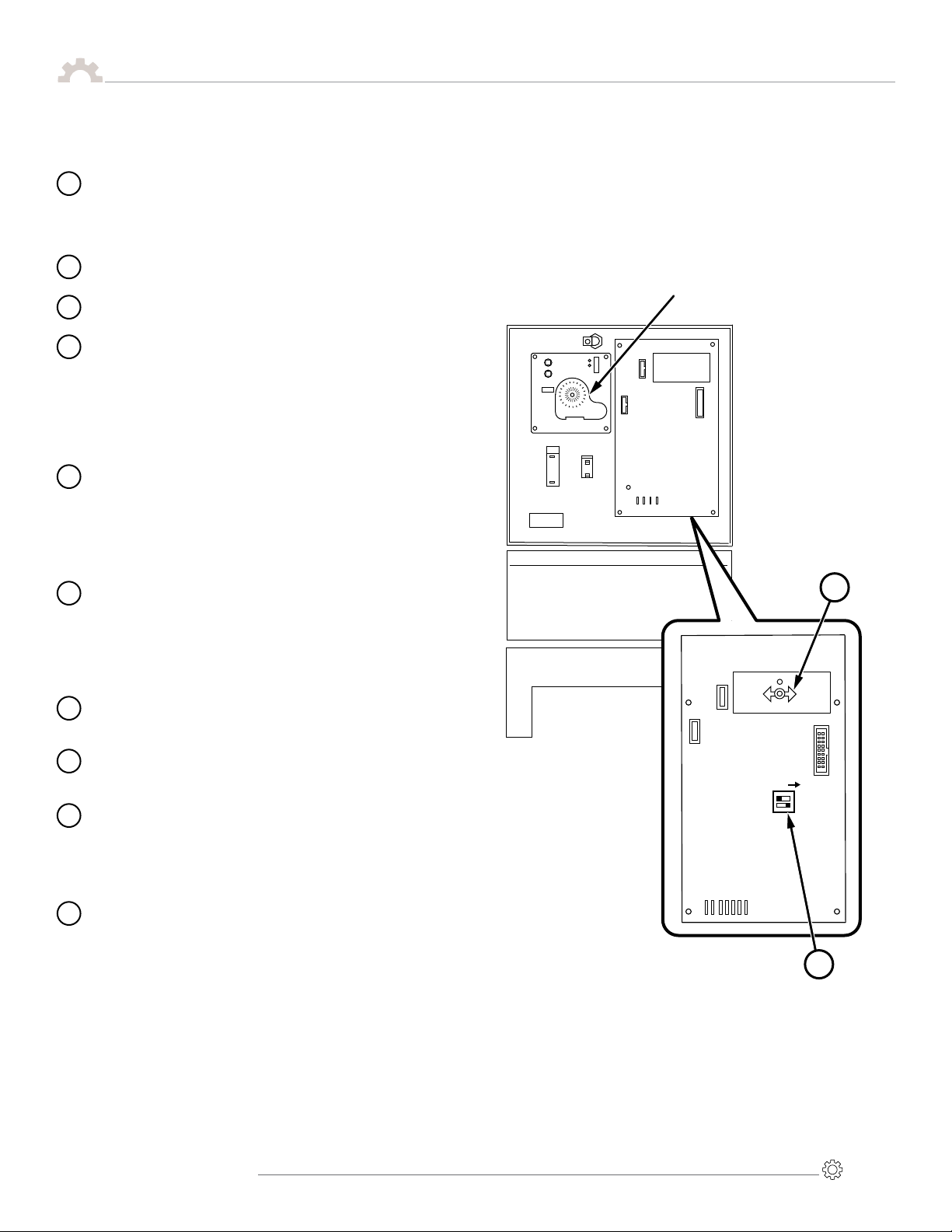
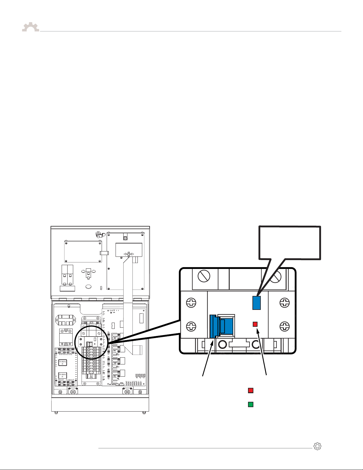
Ground Fault Equipment Protection (GFEP)
Genesys 2 340-222
Set Mode Run Mode
Ground Fault Equipment Protector (GFEP)
Indicator Window
ON - Hose and Gun Zones
are Active
OFF - Hose and Gun Zones
are Inactive
ON/OFF Switch
(Pictured in ON Position)
TEST
LOAD
LINE
Test every 3 months
per manufacturer’s
recommendation.
This adhesive dispensing system is equipped with a Ground Fault Equipment
Protector (GFEP) that has been installed on the circuit powering the hose
and gun zones. This GFEP is designed to protect the hoses from
an unintended ground fault.
GFEP must be switched ON (Indicator window RED) for hose and gun
zones to heat.
If a ground fault is detected on any hose or gun zone, the GFEP will
switch OFF (Indicator window GREEN) removing power from all hose
and gun zones.
If the GFEP switches OFF due to a ground fault during operation,
contact HMT Technical Service & Support for assistance.

Page 12 ©2015 Hot Melt Technologies, Inc
Proflex®G9
This Warranty extends to the original purchaser only and commences on the date
of the original purchase.
Any part of the Hot Melt Technologies (HMT) adhesive supply unit (ASU)
manufactured by HMT and found in the reasonable judgement of HMT to be
defective in material and workmanship, will be repaired or replaced by HMT without
charge for parts or labor.
This Warranty is limited to:
a) One (1) year from initial use,
b) Eighteen (18) months from date of purchase, or
c) Two thousand (2,000) hours of use, whichever comes rst.
The ASU including any defective part must be returned to HMT within the warranty
period. All transportation expenses to HMT for warranty work and the expense
of returning it to the owner will be paid for by the owner. HMT’s responsibility in
respect to claims is limited to (at its option) making the required repairs, adjustment,
or replacements. No claim of breach of warranty shall be cause for cancellation of
the contract of sale of any HMT ASU.
This warranty does not cover any ASU that has been subject to misuse, abuse,
negligence,or accident, or which has been operated in any way contrary to the
operating instructions. Warranty does not apply to any damage to the ASU that is
the result of improper maintenance or installation.
This warranty does not cover any ASU that has been altered or modied by the
customer. In addition, the warranty does not extend to repairs made necessary
by normal wear or by the use of hot melt materials in the ASU which in the
reasonable opinion of HMT are either incompatible with the ASU or adversely affect
its operation, performance, or durability. This warranty does not extend to any
accessory attachments to the ASU that are warranted separately for different periods
of time. Other components supplied by HMT as part of a system will carry
the warranty of the original manufacturer.
This warranty does not extend to an ASU damaged during shipment. Risk of loss or
damage to the ASU shall pass to the buyer.
HMT reserves the right to change or improve the design of any ASU, or part of an
ASU, without assuming any obligation to modify any ASU previously manufactured.
HMT assumes no responsibility for incidental, consequential or other damages
including but not limited to: expense for hot melts, delivery or return freight
expenses, mechanics travel time, telephone or telegraph charges, rental of a like
product during the time warranty repairs are being performed, travel, loss or
damage to personal property, loss of revenue, loss of use of the ASU, loss of time
or inconvenience.
Warranty Information
Warranty Information
Table of contents


