PROformance Hoops PROVIEW Series User manual
ADJUSTABLE HEIGHT
GOAL SYSTEM
PROVIEW SERIES
554PV

2 www.proformancehoops.com 1-888-353-4667
THANK YOU!
Thank you and congratulations for purchasing a Proformance Hoops Goal - the
finest basketball goal system on the market today! You will discover that
Proformance Hoops is unsurpassed in product innovation, quality and integrity in
the basketball equipment industry. We are focused on designing and engineering
products that meet and exceed the expectations of demanding players and
withstand today’s toughest playing environments.
LAY OUT PLAYING COURT
Consider the following to determine where to install the basketball goal:
Whether the goal is to be installed into a landscaped area next to the playing surface or
into a hard-surfaced area.
Backboard size and its extension distance from the structures.
If court markings are to be used.
Amount of playing surface desired beneath the goal.
Other functions of playing surface (such as driveway, tennis court, etc.)
There must be at least 18” clearance behind the back of the Goal Post to allow room to
operate the goal height adjusting crank.
When the rim is set to the regulation height of 10 ft. the distance from the face of the
backboard to the front of the Goal Post is, depending upon the PROforce (PF) or
PROview (PV) model, shown in the figure below.

1-888-353-4667 www.proformancehoops.com 3
SAFETY INSTRUCTIONS
GOAL ASSEMBLY
IMPORTANT: Concrete must cure a minimum of 72 hours before installing goal.
IMPORTANT: Safe assembly of the goal requires two to three people in good physical
condition and capable of lifting 80-100 lbs (36-45 kg) each.
IMPORTANT: Locate and familiarize yourself with all the parts of the goal before
beginning assembly.
REQUIRED TOOLS AND MATERIALS:
Level
Rubber Mallet
12' Tape Measure
Phillips Screwdriver
Ratchet
Sockets or wrenches:
15mm (9/16")
19mm (3/4")
24mm (15/16")
27mm (1-1/16")
Failure to follow these safety instructions may result in serious injury or death and/or
property damage.
Do not install or use this product unless the instructions within this manual have been carefully
read and understood.
Consult Proformance Hoops if you do not understand the instructions in this manual or need
additional information
Know what’s below ground. “Call before you dig” the hole for the ground anchor. For the US
the number is 811.
If using a ladder during assembly, use extreme caution. Two or three people are recommended
for safe installation and assembly.
Installation and assembly of this product will require lifting and bending that may result in
injury to anyone not accustomed to this type of activity.
Ensure there are no overhead power lines within a 20 ft. (7m) radius of the goal location.
Climate, corrosion or misuse could result in system failure.
The Safety Rod stops the Main Extension Arm at a rim height of 7 ft (2.13m). Attempting to
adjust further down will damage the Arm. If the Safety Rod is removed, adjustment of the rim
below a height of 6 ft. (1.83m) will cause internal damage to the mechanism.
DO NOT HANG on the rim or any part of the goal system. This includes the backboard, support
braces and net.
During play, especially when performing dunking activities, players should keep their faces
away from the backboard, rim and net. Serious injury could result if teeth or face come in
contact with the backboard, rim or net. Do not wear jewelry or other loose objects that could
become entangled with the net.
Twice yearly, check the goal system for loose hardware, excessive wear and signs of corrosion.
Repair the system before use.
Never play on damaged equipment.

PARTS LIST
4
ITEM QTY DESCRIPTION
A 1 5"x5"Main Post
B 1 Actuator
C 1 Spring-Assist Cartridge
D 1 Pole padding
E 1 Gusset Padding
F 1 Main Extension Arm
G 2 Upper Extension Arm
H 1 Backboard
I 1 Safety rod 20mmdia ITEM QTY DESCRIPTION
J 1 Sleeve for Spring Cartridge 1 2 Nylon Washer M18
K 1 Rim Height Indicator 2 10 Nylon Washer M16
L 1 Flex Rim (Separate pack) 3 2 Nylon Washer M12
M 1 Rim Pad (Pre-attached) 4 1 6mm Lock Pin
N 1 Rim Height Sticker 5 1 Hex Bolt M18x320mm
6 3 Hex Bolt M16x320mm
U1 1 Anchor Template 7 1 Hex Bolt M16x245mm
U2 4 16mm Anchor J-bolts 8 1 Hex Bolt M16x120mm
U3 8 Thick washer for J-bolts 9 1 Hex Bolt M16x135mm
U4 12 Hex nut M16 10 2 Hex Bolt M12x35mm
U5 4 Anchor Rebar 36"L 11 2 Washer forM18 Bolt
U6 4 Lock Washer M16 12 12 Washer forM16 Bolt
13 4 Washer forM12 Bolt
R1 4 Carriage Bolt M10x50mm 14 1 Lock Nut M18
R2 4 Washer M10 15 7 Lock Nut M16
R3 4 Flange nut M10 16 2 Lock Nut M12
UNDERGROUND PARTS
PARTS LIST
HARDWARE LIST
RIM HARDWARE
U1
U2
U4
U4
U4
U5
U6
U3
U3
A
B
C
F
G
G
H
IJ
K
L
N
5
11
11
14
6
12
12
12
15
7
12
2
12
15
6
12
2
12
15
R2 R3
R1
12 8
9
2
2
12
15
10 13
313 16
16 13 313 10
4
2
Crank

5
! !
WARNING
STEP1
A.
B.
C.
STEP2
A.
Nylon washer #1 may
be factory installed
14 11
11 5
Rubber pad
face upward.
A
F
1
Slide the Main Extension Arm (F) over the top of the
Main Post (A) and attach to the lower pivot tube
welded on front side of Pole (A) with one Hex bolt
M18x320mm (#5), two Flat washer M18 (#11), two
Nylon washers M18 (#1), and one Lock nut M18
(#14).
Do not over tighten this bolt and nut.
Note: make sure the Nylon washers locate between Main
Extension Arm (F) and Main Post (A).
U6
U3
U4
FIGURE 1B
Playing Court
Back
FIGURE 1C
FIGURE 1A
U3
U2
Slide a 18mm Thick Washer (U3) over each of the J-Bolts (U2) as shown in FIGURE 1A.
Remove the Padding from Main Post (A). Place the Main Post (A) over the J-Bolts. Slide a
16mm Thick Washer (U3), a Lock washer 16mm (U6) and thread a 16mm Hex Nut (U4) to each
J-bolt. Tighten the Nuts only a few turns onto the J-Bolts as shown in FIGURE 1B.
If the Main Post (A) is not exactly vertical, adjust the 16mm J-Bolt Hex Nuts (U4) located under
the Post base. Tighten all of the Hex Nuts (U4) Above Post base when Main Post (A) is vertical.
NOTE: Face the Main Post (A) with Actuator Bracket facing away from playing court (as shown in FIGURE
1C).
6
STEP 3
STEP 4
A.
STEP 5
A. Attach the 2 Upper Extension Arms(G) to Main Post (A) with a Hex
(#7), two Flat Washers M16(#12), 2 Nylon washersBolt M16x245mm
(#2), one Lock Nut M16 (#15).
Do not tighten at this time.
F
A
C
B
8
12
2
12
15
2
2
12
15
6
12
9
12
2
2
12
15
B
A
6
12
12
15
F
Removable
crank handle
7
12
2
G
G
2
12
15
FA
A.
B.
C.
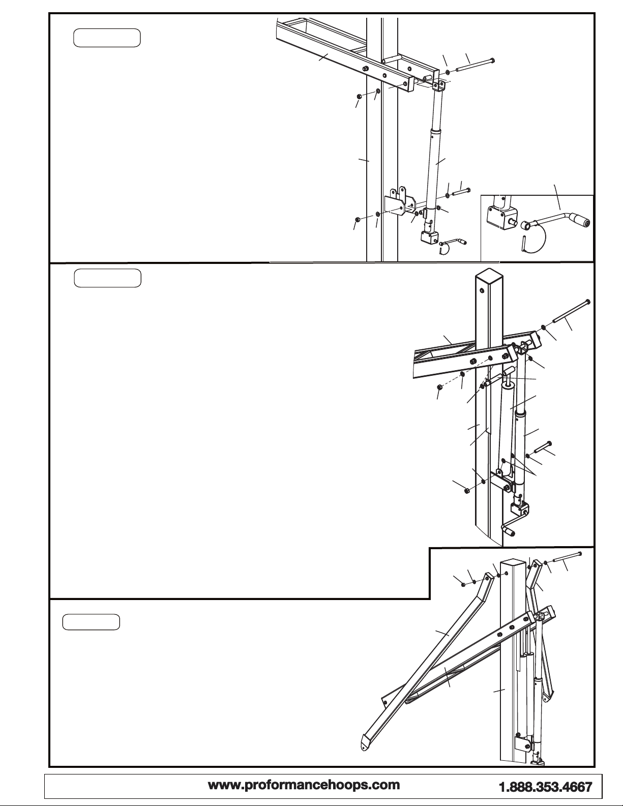
Connect Actuator to Main Extension arm.
Place the upper bracket of Actuator(B) between
the last set of welded tubes on the Main Extension
Arm (F), attach the two parts using Hex bolt M16X320mm
(#6), two Flat Washers M16 (#12), one Lock nut (#15).
Connect Actuator(B) to the mounting bracket welded
in the middle of Post (A), using one Hex Bolt
M16x135mm (#9), two flat Washers for M16 Bolt (#12),
two Nylon Washers (#2), and one Lock Nut for M16 bolt
(#15).
Note: make sure Nylon washers go between Actuator and
Mounting Bracket.
Attached Crank handle to the actuator. Slide Removable
Crank handle onto the shaft sticking out of Gear Box
(Actuator), lock it in place with attached pin.
Slide Steel Sleeve (J) thru the tube welded at the top end of Spring-
Assist Cartridge (C). Slide the Rim Height Indicator (K) over Steel
sleeve, leave it beside the Spring-Assist Cartridge (C).
Place the top of Spring-Assist between Main Extension (F), align the
Steel Sleeve (J) with the second set of welded tubes on the Main
Extension Arm (F), slide one Washer M16 (#12) over one Hex Bolt
M16x320mm (#6), and slide this Bolt all the way thru Main Extension
Arm (F), one Nylon washer M16 (#2), Steel Sleeve (J), another Nylon
washer (#2), and the other side of Main Extension Arm (F).
Secure it with one Flat washer M16 (#12), one lock nut M16 (#15).
Do not over tighten this bolt because this is the pivot point.
Make sure the Plastic Rim Height Indicator (K) hang freely along side
of Spring-Assist Cartridge.
Note: Nylon washer locates between Steel sleeves (J) and Main Extension
arm (F).
J
K
B.
C.
Attach the bottom of Spring-assist Cartridges (C) to the Main pole Bracket
by using a Hex Bolt M16x120mm (#8), two Flat Washers M16 (#12), two
Nylon Washer M16 (#2) and one Hex Nut M16 (#15).
Note: Nylon washer goes between Pole bracket and (C).Cartridge
Remove and discard the Steel spreader bracket from the Spring-Assist
Cartridges (C).

7
STEP 8
A. After everything is square, make sure all nuts on the
system have been tightened.
NOTE: But do not over tighten the Nuts, make sure the unit
can be adjusted up and down.
B. To apply the Rim Height Sticker(In the manual pack), first use
a tape measure to crank rim up to exactly 10’ from the playing
surface. Use a pencil to make a mark on the Spring-assist
Cartridge(C) where the bottom of the Rim Height Indicator(K)
stops. Then, peel and apply Rim Height Sticker to outside
of Spring-assist Cartridge(C) lining up the pencil mark with the
C. Attach Post Pad and Gusset Pad to Main Post(A) as shown.
B.Mount the rim to the Mounting bracket on Backboard(H)
using the hardware supplied in rim box.
NOTE: Use a level to make sure rim is level side to side
before tightening nuts.
STEP 7
A.
B.
Remove the screws on Rim spring box cover, open
the Spring box.
Re-attach Spring box cover to the Rim with removed
screws.
A.
C.
10
B
A
4
I
Rim Height
Sticker
C
Slide Safety Rod (I) thru the tube welded on the backside
of Main Post (A), align the holes each other and secure it
with one Lock Pin 6mm (#4). See detail .B
D.
F
GH
10
13 313 16
16
13
3
13 10
G26
12
12
15
R1 R2 R3
L
H
Crank the Main extension arm as low as possible.
Attach the Backboard to Main Extension Arm (F) by
using a Hex Bolt m16x320mm (#6, two M16 Flat
Washers(#12), two Nylon washers (#2) and one Lock Nut
M16 (#15).
Note: Nylon washers go between Main extension arm Bracket
(F) and Backboard mounting bracket.
Connect Upper Extension Arms (G) to Backboard
(H), using 2 Hex bolts M12x35mm (#10), 4 Flat
Washers M12 (#13), 2 Nylon washers M12 (#3) and
2 Lock nuts M12 (#16).
Note: Put Nylon washers between backboard plate and
Upper extension connecting plate.

8 www.proformancehoops.com 1-888-353-4667
WARRANTIES
BUYER AGREES THAT ALL PRODUCTS SOLD BY PROFORMANCE HOOPS CARRY THE FOLLOWING WARRANTY
Subject to proper installation, and normal intended use, all structural components of ProView Series*, Pro Series*, Force Series*,
and Wall Mount Basketball Systems are warranted to the original owner to be free of defects in materials and workmanship for the
duration of ownership by the original retail purchaser, subject to the limitations below. The Basketball Systems will be covered by this
warranty for a period of five years. Proformance Hoops shall have the right to require the purchaser to deliver the allegedly defective
products to Proformance Hoops for testing, repair, or replacement. Proformance Hoops shall not be responsible for any expense
associated with the replacement or removal of the product from its application for such delivery. Freight and Handling charges may
apply to covered warranty parts. Modification of any product by the customer, unless approved by Proformance Hoops, will void all
warranty. Where listed as “LIMITED”, the warranties shall cover damage of failure that occurs during the course of NORMAL or
INTENDED USE of the product. Normal or intended use shall be described as activity that is necessary for the participation in the sport
for which the equipment is damaged. NOT COVERED is damaged caused by deliberate hanging, multiple player hanging, vandalism,
non-basketball activities, or any other activity that could be regarded as abusive.
Padding Warranty: Multi-Purpose Backboard Edge Padding: one year limited; Indoor Backboard Edge Padding: five year limited
(indoor only); Custom-Fit Pole Padding: one year limited; Wrap-Around Pole Padding: one year limited.
NOT COVERED BY THIS WARRANTY
Use in non-residential applications of Glass backboards.
Use in non-residential applications of Tradition complete systems.
Any products subjected to abuse, negligence, improper installation, vandalism, acts of God, alteration of product or any other
events beyond the control of Proformance Hoops.
Paint or rusted parts.
Deterioration of product due to time and wear.
Normal deterioration of products due to atmospheric conditions, weather, rust, wear and tear (including paint), or other causes that do
not affect functional use are not covered by Proformance Hoops warranties. All warranties are valid only when product is used in the
intended application, and when installed according to Proformance Hoops instructions. Warranty will be void if maintenance
instructions in the Owner’s Manual are not followed, including jack lubrication on a bi-yearly basis. If you did not receive an Owner’s
Manual, please contact ProformanceHoops.com and one will be sent to you.
WARRANTY CLAIMS: All returns must be arranged through the local dealer if available. Warranties do not cover dealer service
charges, labor charges, freight or travel expense associated with replacement, repair, or removal of warranty item. A warranty claim
form must be completed, and photos submitted for any item you wish to claim under warranty. If the purchase was not made through a
dealer, this form is available by email. In response to your claim, you will receive an order confirmation as well as a notice stating
whether Proformance Hoops needs your warranty item returned. Proformance Hoops will notify you if we determine that the item
cannot be claimed under warranty. Proformance Hoops is not responsible for any charges for labor to install or repair defective
product prior authorization. Proformance Hoops will determine the most economical method to either repair or replace
product before any work is to commence.
TO THE MAXIMUM EXTENT PERMITTED BY LAW, THIS WARRANTY AND THE REMEDIES SET FORTH HEREIN ARE
EXCLUSIVE AND EXPRESSLY IN LIEU OF ALL OTHER WARRANTIES, EXPRESSED OR IMPLIED, INCLUDING WARRANTIES
OR MERCHANTABILITY OR FITNESS FOR A PARTICULAR PURPOSE. IF PROFORMANCE HOOPS CANNOT DISCLAIM OR
EXCLUDE IMPLIED WARRANTIES UNDER APPLICABLE LAW, THEN TO THE EXTENT POSSIBLE ANY CLAIMS UNDER SUCH
IMPLIED WARRANTIES SHALL EXPIRE OR EXPIRATION OR THE APPLICABLE WARRANTY PERIOD. SOME STATES DO NOT
ALLOW LIMITATIONS ON HOW LONG AN IMPLIED WARRANTY LASTS, SO THE ABOVE LIMITATION MAY NOT APPLY TO
YOU. PROFORMANCE HOOPS DOES NOT ASSUME OR AUTHORIZE ANY PERSON TO ASSUME FOR US, ANY OTHER
LIABILITY IN CONNECTION WITH THE SALE OF OUR PRODUCTS.
TO THE MAXIMUM EXTENT PERMITTED BY LAW, PROFORMANCE HOOPS ASSUMES NO RESPONSIBILITY FOR
INCIDENTAL OR CONSEQUENTIAL DAMAGES, WHICH MAY ARISE FROM THE PURCHASERS OR USE OF OUR EQUIPMENT.
SOME STATES DO NOT ALLOW THE EXCLUSION OR LIMITATIONS OF INCIDENTAL OR CONSEQUENTIAL DAMAGE, SO THE
ABOVE LIMITATION OR EXCLUSION MAY NOT APPLY TO YOU.
IF ANY PROVISION OF THIS WARRANTY IS INVALID, VOID OR UNENFORCEABLE IN ANY INSTANCE OR RESPECT, THE
UNENFORCEABLE PROVISION WILL BE SEVERED AND REFORMED TO EFFECT THE INTENT OF THIS LIMITED WARRANTY
TO THE MAXIMUM EXTENT POSSIBLE, AND THE REMAINING PROVISIONS SHALL CONTINUE IN FULL FORCE AND EFFECT
AND SHALL BE ENFORCED TO THE FULL EXTENT PERMITTED BY LAW.
This warranty gives you specific legal rights, and you may also have other rights, which vary from state to state
0415
This manual suits for next models
1
Table of contents
Other PROformance Hoops Accessories manuals


Popular Accessories manuals by other brands


CARLO GAVAZZI
CARLO GAVAZZI DLI-P360L M Series instruction manual

Axis
Axis 0734-001 installation instructions

turck
turck RU130U-M18E-LI8X2-H1151 quick start guide

Skov
Skov DOL 68 Technical user guide

Craftsman
Craftsman 486.24508 Assembly instructions

Landscape Forms
Landscape Forms Connect 2.0 installation guide

GRASS VALLEY
GRASS VALLEY 8964FS - datasheet

Cedes
Cedes GridScan/Pro SI Installation and operation manual

CAS
CAS CI-6000A Series manual

PCB Piezotronics
PCB Piezotronics Y482B06 Installation and operating manual

Apogee Instruments
Apogee Instruments SU-200 owner's manual

Vernier
Vernier Go Direct Light and Color GDX-LC manual