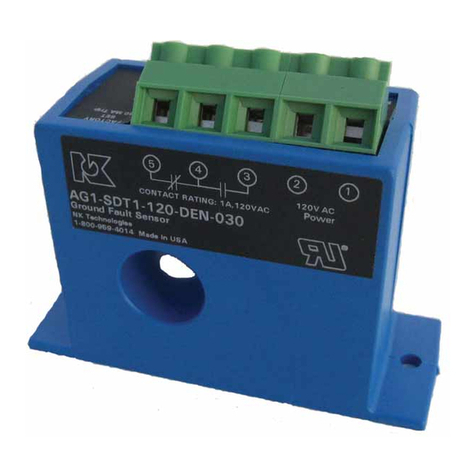
SSK SDIS - 1050 User manual

USER MANUAL
Universal position sensor and
hot metal detector
SDIS – 1050

1. Introduction
SDIS is universal configurable sensor for the detection of hot metal and its position. For its
versatility can sensor operate as a hot metal detector (responds to the presence of hot material),
or as a loop scanner (determines the position of the material in the field of view).
Main advantages of SDIS are high speed scanning, comfortable and easy setting and displaying
parameters using the push buttons and display on the unit or remote (RS232, RS485), wide set
of options, two independent sets of detection parameters and switching between them (also
remotely).
2. Principle of operation
SDIS is a scanning sensor. Its field of view is scanned by polygonal mirror. When a hot product
crosses the scanned field of the sensor, the scanned infrared radiation is reflected onto the
photocell of sensor and electronically processed. Depending on the intensity of infrared
radiation is possible to determine whether the requested material is in the field of view, and
according to the current position of the mirror can be derived material position in the field of
view.
The sensor uses highly reliable and proven PbS photocell, designed with regard to the
requirements of the steel industry. The spectral response of a PbS, unlike other types of infrared
radiation detector covers a wide range of hot metal and steel is from 250 ° C.
SDIS scanning system is designed so that the infrared radiation is reflected to the photocell from
each facet of rotating mirror very accurate, even in the case when the entire sensing field is
covered with hot material. Radiation received by photocell is modulated by a rotating mirror. It
provides:
increasing the signal/noise ratio, which allows detection at low temperatures
independent of the interfering background
suppression hysteresis and overload of photocell
increase the life of photocells
Photocell signal processing is performed in modern digital signal processor, enabling fast,
accurate and stable evaluation, wide range of possibility to set of evaluation parameters with
regard to the environment and thus achieve high reliability sensor independently of steam,
scale, material, temperature fluctuations, etc. Parameter setup is simple and intuitive. Thanks to
the built-in display and buttons directly on the device the parameters can be easily monitored
(or change) directly on the sensor. With built-in communication via RS232 and RS485 sensor
can be adjusted and monitored remotely using a PC.
The sensor can operate in two modes:
LS - Loop Sensor - i.e. a sensor for measuring the position of hot material edges in the sensor
field of view. In this mode the sensor must be therefore positioned so as to be in his field of view
located edge of material. On the edge of the hot material occurs pulse on a photocell. Rotation
angle of the mirror motor at the time of detection of the pulse is directly proportional to the
position of the edge of the hot material in the sensor field of view.

HMD - hot metal detector - a device only detects the exceeding signal amplitude of photocells
over the set threshold. It does not matter if the field of view of the sensor is an edge of the
material. It is necessary to limit field of view (depending on site conditions) by the appropriate
mechanical shutters or cover. (The basic limitation of the field of view is done by shield inside
the sensor - max viewing angle is necessary to specify when ordering).
3. General description
SDIS is a standalone sensor, heavy duty and easy to assembly and commissioning.
Its basic features are:
3.1 Mechanical:
hermetically sealed, accurately machined housing made of aluminum alloy.
suport wall with mounting stand, adjustable in both directions, adapted to the cooling
unit with water and blowing air windscreen to prevent pollution.
connection of water and air in the supporting wall - when necessary the sensor can be
easily replaced without disconnecting water or air.
3.2 Electrical:
connection of all electrical signals via one connector
control using display and buttons
o alphanumeric LED display to show parameters
o 4 buttons for easy parameter setting
o 3 LEDs to display the status:
green - flashes when the unit is in operation
yellow - indicates the presence of material the field of view
red - warning or malfunction of the unit
built-in diagnostics unit:
o detection of exceeding the internal temperature over 60 ° C
o detection of a motor speed failure
o detection of power failure

4. The mounting and wiring
4.1. Location
The distance between the SDIS and the measured product is not critical and depends on the
scanning angle so as to cover the entire measurement field. Measured product may not fill the
entire sensor field of view. Just intersects only a portion of 1 cm ² at a distance of 4 m sensor
The optimal distance between the sensor and the various types of materials are as follows:
Material Distance between product and sensor
Wires with a di
ameter of 5
-
12 mm
0,20
–
3 m
Small bars, 10 × 10 to 40 × 40
0,20
–
4 m
Billets and small beams
0,50
–
6 m
Blooms
minimum 2 m
Thin sheets
1,00
–
6 m
Thick plates
1,00
–
8 m
Slabs
minimum 2m
For very hot products it is the best to place the sensor as far as possible to avoid excessive
destruction due to direct radiation.
For cold and less-emitting products is the signal-to-noise ratio increased by placing sensors in
the shortest possible distance.
The sensing surface should ideally be perpendicular to the measured product.
When selecting the location of the sensor attention to the following must be paid:
Other source of infrared radiation in addition to the measured material can not intersect
the sensor field of view (door furnace, the reflection of the product in the water pool, sun
reflection from shiny metal in the area, etc.)
Field of view of sensor must not be covered with any other product than the product being
measured
4.2. Mounting
SDIS has an adjustable mounting foot allows horizontal rotation
and vertical tilt. Mounting base is fitted with 18 mm hole for
mounting on the structure.
The stand is strong enough to ensure a perfect fit sensor. The sensor
is equipped with connections for enclosure cooling water and
compressed air for cleaning and protection of optics.
They can be used in heavy metallurgical environments (high
temperature, humidity, dust).
In some cases, however, it is useful to protect the sensor with the heat resistant screen and in
the case of excessive steam with additional ventilation. To increase the detection accuracy and
lifetime of the sensor should be mounted on a solid, non-shaking pedestal.
Air
Water

4.3. Electrical connection
SDIS sensor is equipped with a 14-pin connector Amphenol PT.
Specification of Lapp Cable Ölflex Servo FD770 CP:
Multiple core cable: 6 × 2x0, 25 mm ² and 2 x 0.5 mm ² shielded
Rugged design for industrial applications
Outer diameter: 10.3 mm
Minimum bending radius: 50 mm
Each wire is labeled with a different color
Note: Unused cores must be insulated or connected to free terminals.
Note: When disconnecting the cable, plug the sensor connector with protective cover for
protect the contacts from corrosion.
4.4. Connection of air and water
Cooling water and cleaning air is fed to the quick couplers cooling housing that is also the sensor
mounting stand. Cooling housing is separately attached to the sensor, so the sensor can be
replaced without disconnecting the cooling water and air and setting changes the sensor
mounting.
4.4.1. Cooling
The cooling channel housing is positioned, allowing the cooling water sensor.
Conditions for cooling:
The sensor is recommended to cool at ambient temperatures above 50 ° C. Laboratory
tests have shown that a properly cooled sensor can operate at temperatures up to 100 °C.
Specifications of cooling water:
Industrial pure water, maximum temperature 25 ° C
Maximum recommended pressure: 4 bars.
Flow rate: 1 -2 liters / min.
Cooling circuit:
Material: aluminum cooling groove in the housing.
Connection: Hose diameter 10 mm (for quick couplers).
4.4.2. Cleaning air
Compressed air is used to remove dust on the windscreen in front of the sensor. The system is
designed to give the high pressure area in front of the sensor.
System Specifications cleaner air:
Air Quality: Air must be dry, free of grease and dust free
Air pressure: 50 to 120 g / cm ²
Flow: 4-16 l / min.
Connection: Hose 10mm (for quick couplers)

5. Technical specification
5.1. Mechanical
Weight: 4 kg
Adjustable stand with mounting hole dia. 18 mm
Dimensions: see drawing
5.2. Optical
Spectral sensitivity: PbS photocell, range 1-3 micron with a maximum response at 2.2
micron
Temperature range of materials: depends on the material to be scanned:
- For iron and steel from 250 ° C when set to high sensitivity. If it is expected
higher product temperature than 400 ° C, it is not appropriate to set a high sensitivity,
because he could detect scale or reflections.
- For other materials, such as copper, bronze, cast iron, etc. The temperature range
depends on the infrared radiation of the product.
Angles - standard sensor is supplied with a viewing angle of 50 degrees, with a special
mask inside the aperture angle can be reduced to 30 respectively. 10 degrees. Side angle or width
of the scanned field - 3 degrees max
5.3. Electrical
Power:
- Voltage: 24V DC
- Power consumption: 12 VA
Signal the presence of the product:
- Semiconductor: complementary push-pull outputs 0/24VDC 50 mA
- Relay: single-pole switch:
- switching capacity: 250V, 5A max
- closing time: 10 ms
- opening time: 5 ms
"Alarm": push-pull output 0/24VDC 50 mA
- 0V DC power failure, internal temperature or motor speed fault detection
- 24 V DC if no error is detected
Analog signals 4-20 mA
- position of the material
- signal intensity

5.4. Environment
Operating temperature: -10 ° C to +60 ° C.
At an ambient temperature above 40 ° C it is recommended to cool sensor with
industrial water at a temperature up to 25 ° C, pressure of 1-2 bar, flow rate of 1-2 l / min
Protection: IP 65


6. Control
Indication LEDs
green - it is blinking at one-second interval when the devise is turned on and the
program is running
yellow - indicates the presence of hot material
red - lights in case of malfunction (and during startup):
- motor failure (motor is not running at correct speed – also during startup)
- temperature inside the sensor exceeds 60 ° C
Display - main menu
Use buttons [←] and [→] to display measured values and the current setting (not for setting):
Int= 75% current infrared signal intensity
Pos= 50% current position of the material (in operation mode LS - Loop Scanner)
A1=I16.0 Analog1 output – current value in mA (selected I = intensity)
A2=P12.0 Analog2 output – current value in mA (selected P = position)
Set=Rel1 selected set of gain and threshold (Rel/Man, set 1/2)
Gain 25% selected gain
Thre 25% selected threshold
Mode LS selected operation mode of the sensor (LS or HMD)
Laser= 0 press button [↲] to light up the targeting laser for 2 minutes (Laser= 1)
Failure message can be flashing on the display (while the red LED is on and alarm output
signal drops to 0) in case of malfunction:
Alarm!!! Mot= Err motor failure
Alarm!!! Tem=60°C inside temperature exceeds 60°C
Or warning can be displayed during remote test:
Warning! ExtTest! during remote TEST
(devise act as it is detecting material:
- analog outputs have 12 mA
- yellow LED is lighting, output signal material detect is on and
relay is closed)
You can confirm message by button.[↲] and continue to main menu. You can show message
again by pressing button [ ↑ ]. After automatic logout from the menu the message appears
automatically again.
Pressing button [↲] on any main menu item (except Laser = 0), you can login and change the
settings – but this is PIN protected.
Re-pressing of [↲] you are prompted to enter the PIN.

The buttons have their numerical meanings: [↑] = 1 [←] = 2 [→] = 3 [↲] = 4, then confirm PIN
by [↲].
There are two levels of user privileges to change the settings:
Basic - for change the most important parameters- PIN: 3412
Advanced - for adaptation of the sensor on actual measuring site - PIN: 2314
- includes all items of the main menu (PIN: 3412)
Use buttons [←] and [→] for move in menu items, press enter button [↲] to get access to
submenu. Use escape [ ↑ ] button to get up in menu tree. Device remembers browsing history,
you can use buttons [↲] or [ ↑ ] to fast move (e.g. if you change the switching threshold, you
can check the device behaves in main menu and you can get simply back by pressing button
[↲]) few times. Specific value can be changed by pressing [↲] (name will be flashing). Now use
[←] and [→] to change value and confirm it by [↲] (name stops flashing), or go back without
saving by pressing [↑].
Sensor -> ValSet1 -> Thre 25% value set 1, threshold is 25%
ValSet2 -> Thre 50% value set 2, threshold is 50%
Set=Rel Rel – value set is chosen by external relay
Man1 - measure according ValSet1
Man2 - measure according ValSet2
Window -> Beg 5% beginning of measuring window (analog output = 4mA,
position 0%)
End 95% ending of measuring window (analog output = 20mA,
position 100%)
SysInfo -> SDIS1050 model number
SN:12001 serial number
Tem=35°C temperature inside unit (reports alarm after exceeding
60°C)
Logout -> Logout ? confirm to logout (automatically after 10 min)
Display - advanced menu (PIN: 2314)
Use buttons [←] and [→] for move in menu items, press button [↲] to get access to submenu.
Use escape [ ↑ ] button to get up in menu tree. Device remember browsing history, you can use
buttons [↲] or [ ↑ ] to fast move (e.g. if you change the switching threshold. We check the
device behaves in main menu and you can get simply back by pressing button [↲]). Specific
value can be changed by pressing [↲] (name will be flashing). Now use [←] and [→] to change
value and confirm [↲] it (name stops flashing), or to go back without saving button [↑].
Mode LS -> LS - Loop Scanner mode
operation mode - for measurement of hot material position
HMD - Hot Metal Detector
- only for hot material presence detection (without position)

Sensor -> ValSet1 -> Gain 25% gain
detection setting (value set 1) Thre 25% switching threshold
HysT 10% hysteresis of switching threshold
ValSet2 -> Gain 75% gain
(value set 2) Thre 50% switching threshold
HysT 10% hysteresis of switching threshold
Set=Rel Rel – setting set by relay status
Man1 - measure according ValSet1
Man2 - measure according ValSet2
Window -> Beg 5% beginning of measuring window (analog output = 4mA,
position 0%)
End 95% ending of measuring window (analog output = 20mA,
position 100%)
HysB 5% hysteresis at the start of measuring window
HysE 5% hysteresis at the end of measuring window
Distance -> Mat 2.00 distance between device to material (meters)
alternat. window Beg 0.90 distance between laser to begin. of meas. window (meters)
setting End 0.90 distance between laser to end. of meas. window (meters)
Outputs -> AnOut1 I output signal Analog 1 (I=intensity, P=position)
setting of analog AnOut2 P output signal Analog 2 (I= intensity, P=position)
output NoMatOut -> A1 4.0 Analog1 value without material
A2 last Analog2 value without material
Filters -> SiUp 0 detection signal filter – switching on after set amount
pulses (in miliseconds)
SiDo 0 detection signal filter – switching off after set amount
pulses (in miliseconds)
Pos 6 filter of analog position signal-moving average for x ms
(best choice is multiples of 6 – average for 1 mirror
rotation)
Tests -> Laser= 0 laser pointer (0 off, 1 on)
Lamp= R0 testing by IRLED (R0/R1 according relay, M0 off, M1 on)
Signal - detection test (- from photocell signal, 0 off, 1 on)
An1 -.- test Analog1 (-.- from photocell, on set value in mA)
An2 -.- test Analog2 (-.- from photocell, on set value in mA)
Note: All tests are canceled after exit from Tests menu

Comm -> RS232 -> Term ? (=Noname, VT100, SoftCon)
communication type of connection-PC or type of terminal
settings Sp=19200 speed
Par=None parity
Stop= 1 stop-bit
RS485 -> Addr= 0 address
Prot=Asc protocol Ascii, RTU
Sp=19200 speed
Par=None parity
Stop= 1 stop-bit
SysInfo -> SDIS1050 model number
SN:12001 serial number
Fw=6.103 version firmware
UT 25.55 uptime from last power on
Tem=35°C temperature inside unit (reports alarm after exceeding
60°C)
Fact.Res -> Reset ? reset all settings to the original values after confirmation
(you will be automatically logged off)
Logout -> Logout ? logoff after confirmation (automatically after 10 min)
Explanation of sensor function and menu items
Mode (LS/HMD)- sensor mode
Primary function of sensor is LS – loop scanner – sensor for position measurement of the edge
of hot material. In this mode, sensor must be situated so, that the edge of hot material is in his
field of view. If signal from PbS photocell exceeds threshold, then the edge of this signal is
used for detection of material position (usually trailing edge). Angle of rotating mirror in the
moment of detection is proportional to material position in the sensor's field of view.
Additionally sensor can be set to HMD mode – hot metal detector – sensor only detects if
signal from PbS photocell exceeds threshold (menu item Thre). Edge of material does not need
to be in the field of view. Although basic mask inside the sensor is enough usually to limit
sensor's field of view, in some cases it needs to be limited by additional mechanical shields (it
depends on place of installation). Please send us max. viewing angle you need in quotation.
Sensor – detection parameters configuration
There is possibility to configure two parameter value sets (gain, threshold, hysteresis)
and switch between them (also remotely). This is suitable for production lines with different
product profiles. E.g. for thin wire it needs to be higher gain then for thick bars
In each set (ValSet1,ValSet2) there is possibility to adjust gain (Gain), threshold (Thre) and
hysteresis (HysT). Sensor sets output detection signal to on if amplitude of photocell signal
exceeds threshold (Thre), and sets it off if amplitude is below Thre-HysT.
Which value set is actually used can be selected in menu item Set - manually (item Set is set to
Man1 or Man2) or it can be selected remotely by switching relay (item Set is set to Rel).

Window – measuring window configuration
For position measurement there is possibility to adjust measuring window - e.g. narrow max.
field of view range or adjust start and end limits for analog output signals 4 - 20 mA (menu
items Beg and End), and adjust hysteresis to eliminate signal bouncing at the edges of
measuring window (menu items HysB and HysE).
Distance – measuring window configuration by specifying distances
There is possibility to adjust measuring window alternative way, by specifing the distance
between sensor and measured material and distances between start of measured window and
laser pointer and between laser pointer and the end of window. Note: This configuration is not
always accurate, because intensity of infrared signal depends on conditions in the place of
installation.
Outputs – analog outputs configuration
There are two independent analog outputs 4-20 mA in the sensor. It is possible to configure
each output to represent or position or intensity of infrared signal. There is also possibility to
specify value of output in mA, when there is no material detected (menu item NoMatOut).
Filters – configuration of filters and averaging
There is possibility to adjust filters of output signals to improve accuracy or to avoid false
detection. By adjusting SiUp and SiDo values you can specify how many times signal must be
detected befor output detection signal is set on (or off respectively) . Value is in miliseconds.
By adjusting Pos value you can specify moving average of analog output position signal per
miliseconds.
Tests – tests of sensor's function
There is possibility to test various sensor's functions, e.g. to check if it is installed correctly.
You can manually set detection signal to on, set analog outputs to specified value in mA, or to
check detection of infrared signal by switching on infrared LED diode inside the sensor. (Note:
Sensor's IR-LED is situated near the beginning of sensors field of view, so its function can be
checked correctly only in provided software, where you can view pulse). All tests are ended
when you quit menu Tests.
There is also possibility to check sensor's function remotely via test relay. Detection signal is
set to on, and analog outputs are set to 12mA.
Comm – communication configuration
There is possibility to set various parameters of RS232 and RS485 serial communication here.
SysInfo – information about sensor
Here you can see model number, serial number, firmware version, uptime from start and actual
temperature inside the sensor.
Fact.Res – reset of all set values to factory defaults.
Logout – quit setup mode.

7. Connector
Amphenol connector – cable wiring
pin color of wire function
Power:
F red 24VDC/0,5A , protected by fuse T 0,8A
K blue GND
Analog outputs:
A yellow Analog1 signal 4-20mA (intensity or position–depends on setting)
B green Analog2 signal 4-20mA (intensity or position–depends on setting)
Digital outputs (push-pull):
C gray presence of material (detect = 24VDC/max. 50mA)
H ping neg. presence of material (detect = 0VDC/max. 50mA)
M black neg. alarm (all OK = 24VDC/max. 50mA, alarm = 0VDC)
Relay outputs:
E brown (thick w.) presence of material - NO (250V/5A)
L white (thick w.) presence of material - COM (250V/5A)
Relay inputs:
D brown external test (TEST - connect GND)
J white remote change of value sets (connect to GND = switch to Set2).
Communication:
P purple isolated GND for RS485
R red/blue DATA+ RS485
N grey/ping DATA- RS485
Amphenol PT 06 W 12-14 S
Table of contents
Popular Accessories manuals by other brands
Beurer
Beurer UB 53 Instructions for use
Vortec
Vortec VORTEX COOLER 7875 Operation & Safety Instructions
RADEMACHER
RADEMACHER DuoFern Installation and operating instrictions

TGW
TGW NBC Flat Belt Installation, operation & maintenance manual
Topcon
Topcon LS-80A instruction manual
Mantracourt
Mantracourt T24-DWS quick start guide

