Skov DOL 68 Manual

2019.01.10 • 604263
Software version 1.0
DOL 68 Camera Weighing System
Technical User Guide
English: For other language variants of this document we refer to:
Español: Para otras variantes del idioma de este documento, visite:
Français: Pour les versions dans d'autres langues de ce document veuillez consulter:
http://docs.skov.com/1199


DOL 68 Camera Weighing System
Program Version
The product described in this manual contains software. This manual corresponds to:
•Software version 1.1
•It was released in 2019
Product and Documentation Changes
SKOV A/S reserves the right to modify this manual and the product described in it without notice. In case of
doubt, please contact SKOV A/S.
The date of change appears on the front and back pages.
Note
•All rights reserved. No part of this manual may be reproduced in any manner whatsoever without the
express written permission of SKOV A/S.
•SKOV A/S has made every effort to ensure the accuracy of the information contained in this manual.
Should any mistakes or imprecise information occur in spite of this, SKOV A/S would appreciate
being notified thereof.
•Irrespective of the above, SKOV A/S shall not have any liability with respect to loss or damage
caused or alleged to be caused by reliance on any information contained herein.
•Copyright by SKOV A/S.

4 Technical User Guide
DOL 68 Camera Weighing System
1INTRODUCTION...............................................................................................6
2PRODUCT DESCRIPTION...............................................................................6
3PRODUCT SURVEY.........................................................................................7
4GENERAL INFORMATION ..............................................................................8
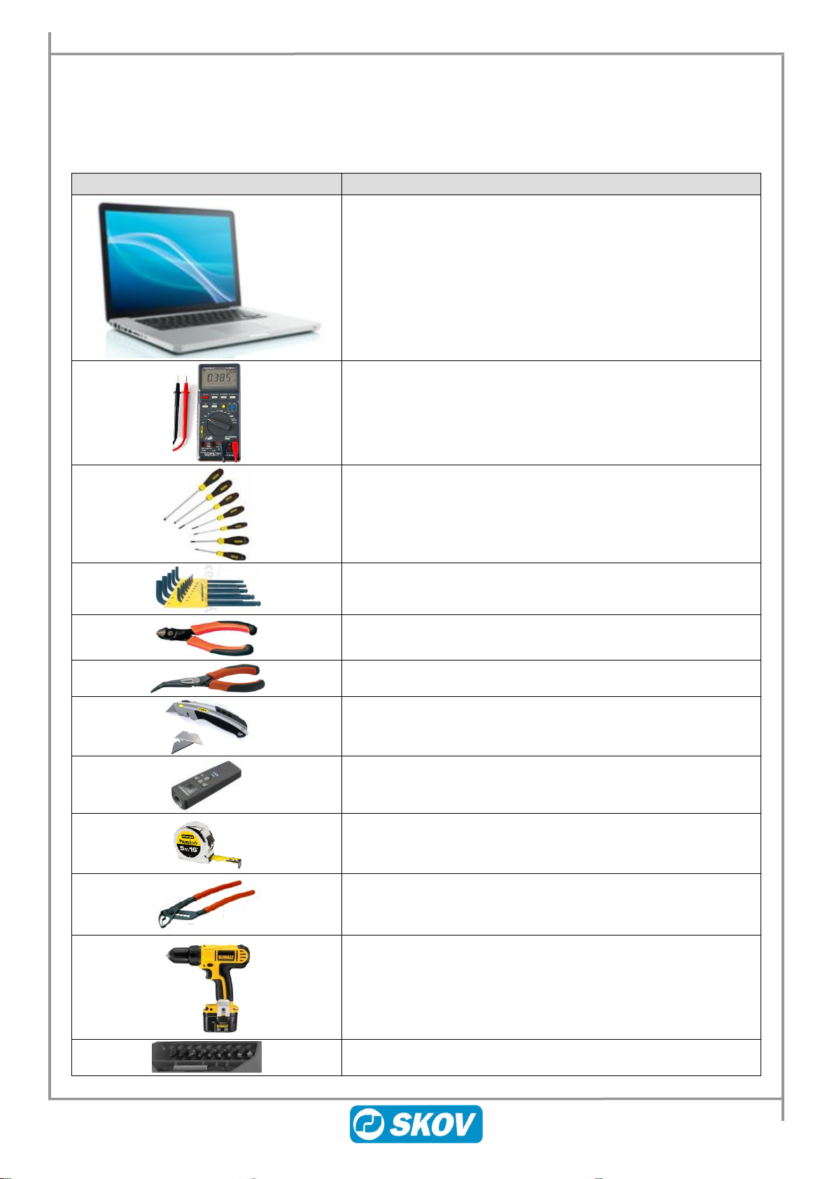
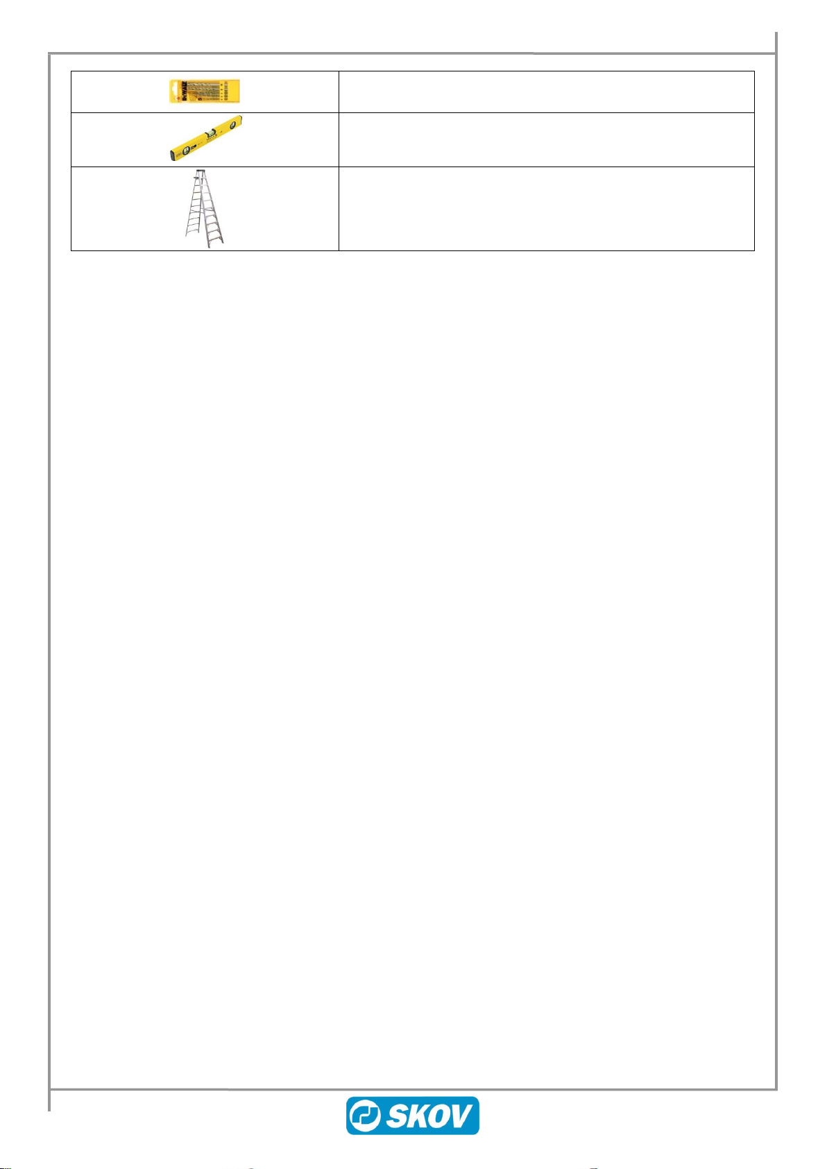
4.1 Recommended tools.................................................................................................8
5MOUNTING GUIDE ........................................................................................10
5.1 Positioning and pen requirements........................................................................10
5.1.1 Weaners............................................................................................................................... 11
5.1.2 Finishers.............................................................................................................................. 11
5.2 Mounting the DOL 68 CWS ....................................................................................12
5.3 Mounting examples ................................................................................................13
5.3.1 DOL 68 camera kit............................................................................................................... 13
5.3.2 Mounting the DOL 68 camera kit on a flat ceiling............................................................ 14
5.3.2.1 DOL 68 camera kit straight onto ceiling................................................................................................15
5.3.2.2 DOL 68 camera kit with mounting rails around piping ..........................................................................16
5.3.3 Mounting the DOL 68 camera kit on sloping ceiling ....................................................... 17
5.3.3.1 DOL 68 camera kit with 1 m mounting rail............................................................................................18
5.3.3.2 DOL 68 camera kit with 2 m mounting rail............................................................................................19
6INSTALLATION GUIDE..................................................................................20
6.1 Electrical connection..............................................................................................20
6.1.1 Cable routing....................................................................................................................... 20
6.1.2 Cable Plan............................................................................................................................ 20
6.1.3 Connection to DOL 68 CWS............................................................................................... 21
6.1.4 Connection in terminal box................................................................................................ 22
7USER GUIDE..................................................................................................23
7.1 IP configuration ......................................................................................................23
7.1.1 Static IP address for PC ..................................................................................................... 23
7.1.2 Camera................................................................................................................................. 24
7.1.3 DOL 68 CWS........................................................................................................................ 25
7.2 DOL 68 CWS Setup.................................................................................................26
7.3 Overview of Menus.................................................................................................26
7.3.1 Main...................................................................................................................................... 26
7.3.2 Setup.................................................................................................................................... 26
7.3.2.1 Cameras................................................................................................................................................27
7.3.2.2 Calibration.............................................................................................................................................30

Technical User Guide 5
DOL 68 Camera Weighing System
7.3.3 Maintenance........................................................................................................................ 30
7.3.3.1 Version ..................................................................................................................................................30
7.3.3.2 Logs.......................................................................................................................................................30
8TROUBLESHOOTING GUIDE .......................................................................31
8.1.1 Camera................................................................................................................................. 32
9TABLE FOR ROI SIZES.................................................................................35
10 TABLE FOR IP ADDRESSES........................................................................35
11 MAINTENANCE GUIDE .................................................................................36
11.1 Cleaning...................................................................................................................36
11.1.1 Camera................................................................................................................................. 36
11.1.2 DOL 68 CWS........................................................................................................................ 36
12 TECHNICAL DATA.........................................................................................37

6 Technical User Guide
DOL 68 Camera Weighing System
1 Introduction
This manual covers the assembly, installation and set-up of the DOL 68 CWS Camera Weighing System. The
manual provides the user, installer and electrician with the basic knowledge about the system’s functions
needed to make optimum use of the DOL 68 CWS. Please read through the entire manual prior to
commissioning the system.
The installation section is intended primarily for electricians commissioning and servicing the system.
Please be aware that no electrical equipment may be opened without first removing the supply voltage, and
service and troubleshooting may only be done by qualified personnel.
2 Product description
The DOL 68 CWS is used to estimate the gain of weaners or finishers. The system is part of the FarmOnline
system for production monitoring of weaners and/or finishers. It requires FarmOnline Explorer version 3.4 or
later to be installed on a PC with local internet access to DOL 68.
The camera weighing system provides the farmer valuable information about the current average weight of the
pigs in a pen, and the size of the variation in the pigs’ weight. The pigs’ daily growth can be calculated from the
measurements taken. This will enable the farmer to respond to the factors affecting the pigs’ growth.
The system comprises a CWS computer and between two and four cameras. Each camera also comes with a
lamp to ensure correct lighting. Each camera records a number of images every 24 hours; based on those
images, the CWS computer calculates the pigs’ weight, which is then used to compute the average and the
variation in weight together with daily growth.
Figure 1: Camera in pen

Technical User Guide 7
DOL 68 Camera Weighing System
3 Product survey
Check that the parts ordered are present and undamaged before starting work.
DOL 68 Camera Weighing System
130452 DOL 68 CWS 4IN
Up to 4 cameras per DOL 68 CWS can be connected.
One DOL 68 CWS per section must be used.
130454 DOL 68 camera kit
The camera kit contains camera, light, terminal box, rail and
mounting fixtures.
The camera kit can be mounted straight onto a flat ceiling if the
ceiling height is correct relative to the type of animal.
See section with mounting examples 5.3.
130445 Mounting rail 15x30.5x1,000 mm, A2
130446 Mounting rail 15x30.5x2,000 mm, A2
For mounting DOL 68 camera kit on ceiling.
Use the number of mounting rails necessary to position the DOL 68
camera kit correctly relative to ceiling height and type of animal.
See section with mounting examples 5.3.
130447 DOL 68 rail mounting kit
Includes:
2 x 504051 Angle bracket 62x30x3, A2
8 x 352026 Machine screw M8x14 cyl Allen A2 DIN912
8 x 570925 M8 threaded plate
2 x 352824 Lock nut M8 A2 DIN985
4 x 352835 Washer ø8,4/ø16x1,6 A2 DIN125A
2 x 352027 Machine screw M8x30 cyl Allen A2 DIN912
See section with mounting examples 5.3.
130632 LAN switch, 8 ports
Use the LAN switch if extra ports are needed.
Position switch central in the network.
Max. 100 m CAT5e STP cable.
Has its own 230 V AC power supply.
8 RJ45 ports. STP cable.
301216 Network CAT6 shielded cable 0.5 m
301217 Network CAT6 shielded cable 2 m
301218 Network CAT6 shielded cable 10m
301219 Network CAT6 shielded cable 30m

8 Technical User Guide
DOL 68 Camera Weighing System
4 General information
4.1 Recommended tools
The list below shows the tool(s) recommended for assembling and fitting the CWS computer and cameras.
Topic
Description
Computer
Multimeter
Screwdriver set
Allen key kit
Side cutter
Needle-nose pliers
Knife
Laser distance meter
Tape measure
Water pump (multi-grip) pliers
Cordless drill
Screwdriver bits

Technical User Guide 9
DOL 68 Camera Weighing System
Drill bits, various sizes
Spirit level
Ladder

10 Technical User Guide
DOL 68 Camera Weighing System
5 Mounting guide
Check that the parts ordered are present and undamaged before starting work. Please read through the entire
guide before starting assembly and fitting.
5.1 Positioning and pen requirements
•Adjust the system to weigh either 6-30 kg weaners or 30-130 kg finishers.
•At least 2 cameras must be used, divided between two pens in each section.
•Cameras must be placed above pens with pigs that are representative of the whole section.
•A maximum of 4 cameras per DOL 68 CWS can be connected.
•There must be at least 15 pigs in the pen where the camera is located.
•Cameras must be positioned so there is provide a clear view of a measurement area of 1.5 x 1.5 m
for weaners and 2 x 2 m for finishers.
•The cameras should cover all feeding spaces as far as possible.
•The minimum and maximum height for installing the camera is 1.6-2.0 m for weaners; for finishers
it is 2.2-2.6 m.
•If there is more than one floor height within the measuring range, you have to anticipate a higher
inaccuracy in the results.
•It must be possible to mount the camera in a stable position.
•It is essential that the floor is a stark contrast to the pale color of the pigs. In other words, the surface
where the pigs are monitored must have a dark color.
•The floor in front of a feed dispenser is subject to a lot of wear and is therefore often fitted with
plates. The plates should not have a pale color.
•Also, there may be problems with lack of contrast when:
•The pigs wallow
•There is a lot of feed on the floor
•Sawdust is scattered on the floor
•The light for the camera must be timer-controllable. This can be done using either the timer in the
DOL 635/DOL 639 or an external timer.
•The distance from cameras to the DOL 68 CWS and from the DOL 68 CWS to the FarmOnline
computer switch must not exceed 100 m.
•FarmOnline Explorer version 3.4 or later must be installed on a PC with local Internet access to the
DOL 68 (same IP subnet).

Technical User Guide 11
DOL 68 Camera Weighing System
5.1.1 Weaners
Measurement area with clear view of weaners 1.5 x 1.5 m. There should not be any lamps and other devices
suspended from the ceiling in the monitored area around the feed trough. It can prevent the camera from getting
good pictures and reduce the number of weighings.
Figure 2: Siting of two cameras in a section with weaners.
5.1.2 Finishers
Measurement area with clear view of finishers 2 x 2 m. There should not be any lamps and other devices
suspended from the ceiling in the monitored area around the feed trough. It can prevent the camera from getting
good pictures and reduce the number of weighings.
Figure 3: Siting of two cameras in a section with finishers.

12 Technical User Guide
DOL 68 Camera Weighing System
5.2 Mounting the DOL 68 CWS
1) Knock out the number of knock-outs in the cabinet base needed for feed and LAN cables.
2) Remember clearance around the cabinet:
•43 cm (A) so that the cover can be positioned on top of the cabinet base when servicing.
•10 cm (B) at the bottom.
•5 cm (C) at the sides.
3) Mount the DOL 68 CWS with Ø5 mm screws according to the distance measurements in the drawing.
Figure 3: Mounting the DOL 68 CWS

Technical User Guide 13
DOL 68 Camera Weighing System
5.3 Mounting examples
5.3.1 DOL 68 camera kit
Position the light source in a way that lessens the
shadow incidence.
The challenge is often the shadows formed by the
shoulders of the pig.
Position the light source at a slightly slanted angle to
light up under the feed dispenser. In this way, the
light is directed towards the pig’s shoulders when it
eats. It yields the best result.
The camera height must be between 1600-2000 mm
for weaners, and 2200-2600 mm for finishers
respectively.
Camera height shall be measured from the lowest
point on the camera to the floor.
Place the camera at a distance of 600-800 mm from
the partition with the arrow pointing towards the
feed dispenser.
Check the camera angles in the table below, if there
is a need for placing the camera close to devices
suspended from the ceiling.
Distance
below the
camera [mm]
Width X [mm]
Length Y
[mm]
250
300
210
500
600
450
1000
1200
900
1500
1800
1350
2000
2400
1800
Adjust the camera so that it points straight down on
the floor.
If necessary, use a small spirit level.

14 Technical User Guide
DOL 68 Camera Weighing System
5.3.2 Mounting the DOL 68 camera kit on a flat ceiling
Mount camera with:
2 x Screw M8x14 cylind. int.
hexag. A2 DIN912
2 x M8 threaded plate
Mount terminal box with:
2 x Machine screw M4x16 cyl
Allen A2 DIN912
2 x M4 threaded plate
Mount LED light with:
2 x Screw M6x10 cylind. int.
hexag. A2 DIN912
2 x M6 threaded plate

Technical User Guide 15
DOL 68 Camera Weighing System
5.3.2.1 DOL 68 camera kit straight onto ceiling
In this example, the following has
been used:
1 x 130454 DOL 68 camera kit
Screws for mounting rail onto the
ceiling are not supplied.
Figure 4: Example of mounting straight onto a flat ceiling

16 Technical User Guide
DOL 68 Camera Weighing System
5.3.2.2 DOL 68 camera kit with mounting rails around piping
In this example, the following have been used:
1 x 130454 DOL 68 camera kit
2 x 130447 DOL 68 rail mounting kit
2 x 130445 Mounting rail 15x30.5x1000 mm, A2
Screws for mounting rails onto the ceiling are not
supplied.
Figure 5: Example of mounting around piping

Technical User Guide 17
DOL 68 Camera Weighing System
5.3.3 Mounting the DOL 68 camera kit on sloping ceiling
Mount camera with:
1 x Screw M8x14 cylind int 6kt A2 DIN912
1 x Washer ø8,4/ø16x1,6 A2 DIN125A
1 x. Rotary joint for PV24-108 M8
Mount LED light with:
2 stk. Screw M6x10 cylind int. A2 DIN912
2 stk. M6 threaded plate
Mount terminal box with:
2 stk. Machine screw M4x16 cyl. Allen A2 DIN912
2 stk. M4 threaded plate

18 Technical User Guide
DOL 68 Camera Weighing System
5.3.3.1 DOL 68 camera kit with 1 m mounting rail
In this example, the following have
been used:
1 x 130454 DOL 68 camera kit
3 x 130447 DOL 68 rail mounting
kit
5 x 130445 Mounting rail
15x30.5x1000 mm, A2
Screws for mounting rails onto the
ceiling are not supplied.
Figure 6: Example of mounting with 1 m mounting rail

Technical User Guide 19
DOL 68 Camera Weighing System
5.3.3.2 DOL 68 camera kit with 2 m mounting rail
In this example, the following have
been used:
1 x 130454 DOL 68 camera kit
3 x 130447 DOL 68 rail mounting
kit
2 x 130445 Mounting rail
15x30.5x1000 mm, A2
3 x 130446 Mounting rail
15x30.5x2000 mm, A2
Screws for mounting rails onto the
ceiling are not supplied.
Figure 7: Example of installation with 2 m mounting rail

20 Technical User Guide
DOL 68 Camera Weighing System
6 Installation guide
6.1 Electrical connection
Qualified personnel must perform installation, service and fault-finding of all electrical
equipment in accordance with the applicable national and international standard EN 60204-1 and
any other EU standards that are applicable in Europe.
The installation of a power supply isolator is required for each motor and power supply to
facilitate voltage-free work on the electrical equipment. SKOV A/S does not supply the power
supply isolator.
6.1.1 Cable routing
Cabling must be routed into the base through the couplings fitted (couplings not supplied). Armoured cable is
recommended in locations where there is a risk of attack by rodents.
The LAN cables between switch, DOL 68 CWS and cameras must be CAT5e or CAT6 STP LAN cable.
Max. cable length 100 m for CAT5e and CAT6 cables.
6.1.2 Cable Plan
Figure 8: Cable plan
Table of contents
Other Skov Accessories manuals