ProGear Hendrickson HN FR Series User manual
HN FR Service Manual
Pro Gear's Hendrickson HN FR Service Manual to assist in identifying your Hendrickson unit.
If you need any assistance identifying the correct transfer case unit for your truck and
equipment, contact your Hendrickson replacement part specialists at Pro Gear and
Transmission.
Pro Gear Transmission has same day shipping and 1000’s of products in stock and ready to
ship internationally for your next project.
For parts or service contact the Hendrickson specialists at Pro Gear & Transmission, Inc.
1 (877) 776-4600
(407)872-1901
(ffi
HENDRICKSON
/4'e
~m-U
R/1:msClh
Us
®
Pro Gear and Transmission • 906 W. Gore St. Orlando, FL 32805 • 1 (877) 776-4600 / (407) 872-1901 • [email protected]
HN®FR Series Rear Suspension
SUBJECT: Service Instructions
LIT NO: 17730-285
DATE: December 2012 REVISION: A
TABLE OF CONTENTS
Section 1 Introduction . . . . . . . . . . . . . . . . . . . . . . . . 2
Section 2 Product Description . . . . . . . . . . . . . . . . . 2
Section 3 Important Safety Notice . . . . . . . . . . . . . . 4
Section 4 Special Tools . . . . . . . . . . . . . . . . . . . . . . . 7
Section 5 Parts Lists. . . . . . . . . . . . . . . . . . . . . . . . . . 8
Section 6 Preventive Maintenance. . . . . . . . . . . . . 11
Preventive Maintenance Intervals . . . . . . . . 11
Component Inspection . . . . . . . . . . . . . . . . 12
Equalizing Beam End Connection . . . . . . . 13
Axle Brackets. . . . . . . . . . . . . . . . . . . . . . . . 14
Bar Pin End Bushing . . . . . . . . . . . . . . . . . . 15
Bar Pin Shim . . . . . . . . . . . . . . . . . . . . . . . . 15
Bolster Springs . . . . . . . . . . . . . . . . . . . . . . 15
Auxiliary Spring Assembly . . . . . . . . . . . . . . 16
Rebound Strap . . . . . . . . . . . . . . . . . . . . . . 17
Longitudinal and Transverse Torque Rods . . 17
Section 7 Alignment & Adjustments . . . . . . . . . . . 18
Drive Axle Alignment Inspection Procedure . 18
Bar Pin Alignment . . . . . . . . . . . . . . . . . . . . 19
Bar Pin Alignment Shims. . . . . . . . . . . . . . . 21
Auxiliary Spring Shim Evaluation . . . . . . . . . 22
Section 8 Component Replacement . . . . . . . . . . . 23
Fasteners . . . . . . . . . . . . . . . . . . . . . . . . . . 23
Saddle . . . . . . . . . . . . . . . . . . . . . . . . . . . . 23
Auxiliary Spring . . . . . . . . . . . . . . . . . . . . . . 25
Rebound Strap . . . . . . . . . . . . . . . . . . . . . . 26
Bolster Springs . . . . . . . . . . . . . . . . . . . . . . 27
Vee Bracket. . . . . . . . . . . . . . . . . . . . . . . . . 28
Shock Absorbers . . . . . . . . . . . . . . . . . . . . . 29
Equalizing Beam. . . . . . . . . . . . . . . . . . . . . 30
Bar Pin End Bushings . . . . . . . . . . . . . . . . . 34
Section 9 Torque Specications . . . . . . . . . . . . . . . 38
Section 10 Troubleshooting Guide . . . . . . . . . . . . . . 40
-
[H]
TECBNICAL
®
PROCEDURE
[ffi
BENDRICKSON
_7,?e
N/07#
;pves
Oh
Us
®
Pro Gear and Transmission • 906 W. Gore St. Orlando, FL 32805 • 1 (877) 776-4600 / (407) 872-1901 • [email protected]
HN®FR Series
Introduction 2 17730-285
SECTION 1
Introduction
This publication is intended to acquaint and assist maintenance personnel in the preventive
maintenance, service, repair and rebuild of the HN®FR Series suspension system for Fire/
Rescue vehicles.
NOTE Use only Hendrickson parts for servicing this suspension system.
It is important to read and understand the entire Technical Procedure publication prior to
performing any maintenance, service, repair, or rebuild of this product.The information in this
publication contains parts lists, safety information, product specifications, features, proper
maintenance, service, repair and rebuild instructions for the HN FR Series suspension.
Hendrickson reserves the right to make changes and improvements to its products and
publications at any time. Contact Hendrickson Tech Services for information on the latest ver-
sion of this manual at 1-866-755-5968 (toll-free U.S. and Canada), 1-630-910-2800 (outside
The latest revision of this publication is also available online at
www.hendrickson-intl.com
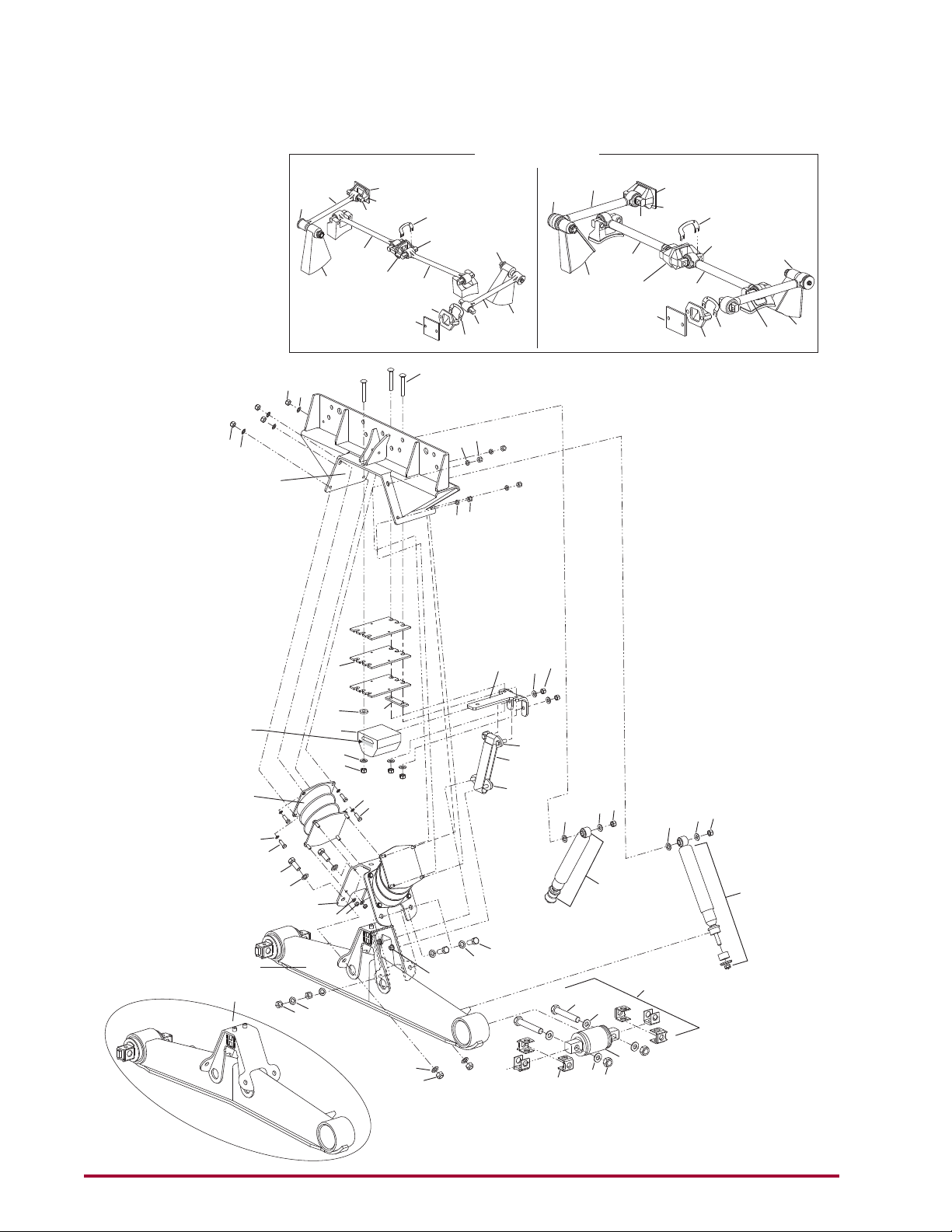
SECTION 2
Product Description
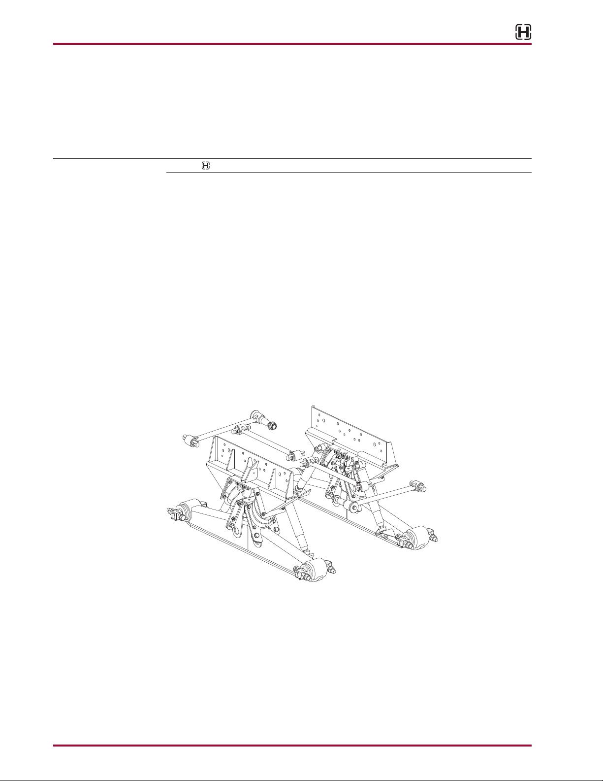
FIGURE 2-1
HN FR Series Suspension System offers an ideal combination of stability, ride quality, light
weight, and articulation.With over a century of experience in the design and manufacturing
of heavy-duty truck suspensions, Hendrickson introduces yet another landmark product for the
fire and rescue industry.The HNFR family of rubber suspensions delivers the exceptional per-
formance that the industry has come to expect from the leader in suspension technology.With
ratings up to 58,000 pounds,the HNFR Series offers a full range of rubber suspensions to meet
the unique needs of the fire and rescue industry.
The innovative spring system allows the equalizing beam to pivot without a need for cen-
ter bushings.The bolster springs, together with rubber bushings in the equalizing beam
ends, accommodate the articulation of the axles without friction or metal-to-metal contact.
'H
l!!J
Pro Gear and Transmission • 906 W. Gore St. Orlando, FL 32805 • 1 (877) 776-4600 / (407) 872-1901 • [email protected]
HN®FR Series
17730-285 3 Product Description
Subsequently, the HNFR Series suspension reduces scheduled maintenance, which helps lower
operating costs.
■ VariRate®Spring System — Delivers a combination of superior stability, articulation and
ride.System can be tailored to meet the specific needs of unique vehicle applications
■ Rubber bolster springs — Diagonally-mounted rubber bolster springs deliver a smooth
ride and outstanding articulation.Wide spring centers enhance stability and eliminate the
need for the cross tube.
■ Auxiliary springs — Engage to provide added stability for more demanding applications.
■ Equalizing beam — Formed and robotically-welded equalizing beam eliminates center
bushings and lubrication requirements — significantly reducing scheduled maintenance;
provides a narrow profile for weight savings; distributes load equally between both axles for
improved traction; and establishes a solid axle connection for improved handling.
■ Bar pin beam end connection — Rugged axle connection extends bushing life and allows
easy axle alignment and serviceability.
■ Saddle / frame brackets — Weight-saving,high-strength design increases carrying capac-
ity and durability.
■ Rebound Control Strap — Protects bolster springs from severe rebound tension
■ Torque Rods — Enhance handling during braking and cornering.Transverse rods ensure
axle position and lateral stability. Longitudinal rods engineered to optimize resistance to
axle wind-up.
HN®FR SPECIFICATIONS
HN 422FR HN 482FR HN 542FR HN 582FR
Installed Weight1888 lbs. 911 lbs. 991 lbs. 1,011 lbs.
Suspension Rating242,000 lbs. 48,000 lbs. 54,000 lbs. 58,000 lbs.
GVW Approval373,000 lbs. 80,000 lbs. 80,000 lbs. 90,000 lbs.
Diagonal Articulation417"
Ride Heights 9.5", 10.5", 11.5", 13.25", 15.5"
Axle Spacing552", 54" 54" 54", 60" 54", 60"
1. Installed weight includes complete suspension at 9.5" ride height and 54" axle spacing.
2. Capacity ratings approved for fire and rescue applications only.
3. Contact Hendrickson for applications that may exceed GVW approval ratings.
4. Suspension articulation may exceed vehicle’s capability and may be limited by vehicle manufacturer; vehicle
manufacturer installed axle stops may restrict suspension’s articulation.
5. Additional beam lengths available, contact Hendrickson Application Engineering.
'H
l!!J
Pro Gear and Transmission • 906 W. Gore St. Orlando, FL 32805 • 1 (877) 776-4600 / (407) 872-1901 • [email protected]
HN®FR Series
Important Safety Notice 4 17730-285
SECTION 3
Important Safety Notice
Proper maintenance,service and repair is important to the reliable operation of the suspension.
The procedures recommended by Hendrickson and described in this technical publication are
methods of performing such maintenance,service and repair.
The warnings and cautions should be read carefully to help prevent personal injury and to
assure that proper methods are used. Improper maintenance, service or repair may damage
the vehicle,cause personal injury, render it unsafe in operation, or void manufacturer’s warranty.
Failure to follow the safety precautions in this manual can result in personal injury and/or
property damage. Carefully read and understand all safety related information within this pub-
lication, on all decals and that provided by the vehicle manufacturer before conducting any
maintenance, service or repair.
EXPLANATION OF SIGNAL WORDS
Hazard“Signal Words” (Danger-Warning-Caution) appear in various locations throughout this
publication. Information accented by one of these signal words must be observed to help mini-
mize the risk of personal injury to service personnel,or possibility of improper service methods
which may damage the vehicle or render it unsafe.
This is the safety alert symbol. It is used to alert you to potential personal injury
hazards. Obey all safety messages that follow this symbol to avoid possible injury
or death.
Additional Notes or Service Hints are utilized to emphasize areas of procedural importance and
provide suggestions for ease of repair.The following definitions indicate the use of these signal
words as they appear throughout the publication.
INDICATES AN IMMINENTLY HAZARDOUS SITUATION WHICH, IF NOT AVOIDED, WILL RESULT IN
SERIOUS INJURY OR DEATH.
INDICATES A POTENTIAL HAZARDOUS SITUATION WHICH, IF NOT AVOIDED, CAN RESULT IN SERIOUS
INJURY OR DEATH.
INDICATES A POTENTIAL HAZARDOUS SITUATION WHICH,IF NOT AVOIDED,MAY RESULT IN MINOR OR
MODERATE INJURY.
NOTE An operating procedure,practice condition,etc.which is essential to emphasize.
SERVICE HINT A helpful suggestion that will make the servicing being performed a little easier and/or faster.
Also note that particular service operations may require the use of special tools designed for
specific purposes.These special tools can be found in the Special Tools Section of this publication.
The torque symbol alerts you to tighten the fasteners to a specific torque value. See Torque
Specifications section of this publication.
'H
l!!J
m
A
DANGER
A
WARNING
A
CAUTION
Pro Gear and Transmission • 906 W. Gore St. Orlando, FL 32805 • 1 (877) 776-4600 / (407) 872-1901 • [email protected]
HN®FR Series
17730-285 5 Important Safety Notice
■ SAFETY PRECAUTIONS
FASTENERS
DISCARD USED FASTENERS.ALWAYS USE NEW FASTENERS TO COMPLETE A REPAIR. FAILURE TO DO
SO COULD RESULT IN FAILURE OFTHE PART,OR MATING COMPONENTS,LOSS OF VEHICLE CONTROL,
PERSONAL INJURY,OR PROPERTY DAMAGE.
LOOSE OR OVER TORQUED FASTENERS CAN CAUSE COMPONENT DAMAGE, LOSS OF VEHICLE
CONTROL,PROPERTY DAMAGE,OR SEVERE PERSONAL INJURY.MAINTAIN CORRECTTORQUE VALUES
AT ALLTIMES.CHECKTORQUE VALUES ONA REGULAR BASISAS SPECIFIED USINGATORQUE WRENCH
THAT IS REGULARLY CALIBRATED.TORQUE VALUES SPECIFIED IN THIS TECHNICAL PUBLICATION ARE
FOR HENDRICKSON SUPPLIED FASTENERS ONLY. IF NON HENDRICKSON FASTENERS ARE USED,
FOLLOW TORQUE SPECIFICATION LISTED IN THE VEHICLE MANUFACTURER’S SERVICE MANUAL.
LOAD CAPACITY
ADHERE TO THE PUBLISHED CAPACITY RATINGS FOR THE SUSPENSION.ADD-ON AXLE ATTACHMENTS
AND OTHER LOAD TRANSFERRING DEVICES CAN INCREASE THE SUSPENSION LOAD ABOVE ITS
RATED AND APPROVED CAPACITIES, WHICH CAN RESULT IN COMPONENT DAMAGE AND LOSS OF
VEHICLE CONTROL, POSSIBLY CAUSING PERSONAL INJURY OR PROPERTY DAMAGE.
MODIFYING COMPONENTS
DO NOT MODIFY OR REWORK PARTS WITHOUT AUTHORIZATION FROM HENDRICKSON. DO NOT
SUBSTITUTE REPLACEMENT COMPONENTS NOT AUTHORIZED BY HENDRICKSON.USE OF MODIFIED,
REWORKED, SUBSTITUTE OR REPLACEMENT PARTS NOT AUTHORIZED BY HENDRICKSON MAY NOT
MEET HENDRICKSON’S SPECIFICATIONS,AND CAN RESULT IN FAILURE OFTHE PART,LOSS OF VEHICLE
CONTROL, POSSIBLE PERSONAL INJURY OR PROPERTY DAMAGE, AND WILL VOID ANY APPLICABLE
WARRANTIES. USE ONLY HENDRICKSON AUTHORIZED REPLACEMENT PARTS.
TORCH/WELDING
DO NOT USE A CUTTING TORCH TO REMOVE ANY FASTENERS.THE USE OF HEAT ON SUSPENSION
COMPONENTS WILL ADVERSELY AFFECTTHE STRENGTH OFTHESE PARTS.A COMPONENT DAMAGED
IN THIS MANNER CAN RESULT IN THE LOSS OF VEHICLE CONTROL AND POSSIBLE PERSONAL INJURY
OR PROPERTY DAMAGE.
EXERCISE EXTREME CARE WHEN HANDLING OR PERFORMING MAINTENANCE IN THE AREA OF THE
EQUALIZING BEAM.DO NOT CONNECT ARC WELDING GROUND LINE TO THE EQUALIZING BEAM. DO
NOT STRIKE AN ARC WITH THE ELECTRODE ON THE EQUALIZING BEAM AND AXLE. DO NOT USE HEAT
NEAR THE EQUALIZING BEAM ASSEMBLY. DO NOT NICK OR GOUGE THE EQUALIZING BEAM. SUCH
IMPROPER ACTIONS CAN DAMAGE THE EQUALIZING BEAM ASSEMBLY, AND CAN CAUSE LOSS OF
VEHICLE CONTROL AND POSSIBLE PERSONAL INJURY OR PROPERTY DAMAGE.
PERSONAL PROTECTIVE EQUIPMENT
ALWAYS WEAR PROPER EYE PROTECTION AND OTHER REQUIRED PERSONAL PROTECTIVE
EQUIPMENT TO HELP PREVENT PERSONAL INJURY WHEN PERFORMING VEHICLE MAINTENANCE,
REPAIR OR SERVICE.
PROCEDURES AND TOOLS
A TECHNICIAN USING A SERVICE PROCEDURE OR TOOL WHICH HAS NOT BEEN RECOMMENDED BY
HENDRICKSON MUST FIRST SATISFY HIMSELF THAT NEITHER HIS/HER SAFETY NOR THE VEHICLE’S
SAFETY WILL BE JEOPARDIZED BY THE METHOD OR TOOL SELECTED. INDIVIDUALS DEVIATING IN
ANY MANNER FROM THE INSTRUCTIONS PROVIDED WILL ASSUME ALL RISKS OF CONSEQUENTIAL
PERSONAL INJURY OR DAMAGE TO EQUIPMENT INVOLVED.
'H
l!!J
A
WARNING
A
WARNING
A
WARNING
A
WARNING
A
WARNING
A
CAUTION
Pro Gear and Transmission • 906 W. Gore St. Orlando, FL 32805 • 1 (877) 776-4600 / (407) 872-1901 • [email protected]
HN®FR Series
Important Safety Notice 6 17730-285
TRANSVERSE TORQUE RODS
HN FR SUSPENSIONS INCORPORATE TRANSVERSE RODS FOR VEHICLE STABILITY. IF THESE
COMPONENTS ARE DISCONNECTED OR ARE NON-FUNCTIONAL, THE VEHICLE SHOULD NOT BE
OPERATED. FAILURE TO DO SO CAN RESULT IN ADVERSE VEHICLE HANDLING, LOSS OF VEHICLE
CONTROL, POSSIBLE TIRE CONTACT WITH THE FRAME, PREMATURE COMPONENT DAMAGE, OR
SEVERE PERSONAL INJURY.
SUPPORT THE VEHICLE PRIOR TO SERVICING
DO NOT AT ANY TIME WORK AROUND OR UNDER A VEHICLE SUPPORTED ONLY ON LIFTING DEVICES.
THE VEHICLE MUST BE SECURELY CHOCKED AND SUPPORTED ON RIGID STANDS OF SUFFICIENT
STRENGTH BEFORE WORK MAY COMMENCE.
PARTS CLEANING
SOLVENT CLEANERS CAN BE FLAMMABLE, POISONOUS, AND CAUSE BURNS. TO HELP AVOID
SERIOUS PERSONAL INJURY,CAREFULLY FOLLOW THE MANUFACTURER’S PRODUCT INSTRUCTIONS
AND GUIDELINES AND THE FOLLOWING PROCEDURES:
1. WEAR PROPER EYE PROTECTION.
2. WEAR CLOTHING THAT PROTECTS YOUR SKIN.
3. WORK IN A WELL-VENTILATED AREA.
4. DO NOT USE GASOLINE OR SOLVENTS THAT CONTAIN GASOLINE. GASOLINE CAN EXPLODE.
5. HOT SOLUTION TANKS OR ALKALINE SOLUTIONS MUST BE USED CORRECTLY. FOLLOW THE
MANUFACTURER’S RECOMMENDED INSTRUCTIONS AND GUIDELINES CAREFULLY TO HELP
PREVENT PERSONAL ACCIDENT OR INJURY.
DO NOT USE HOT SOLUTION TANKS OR WATER AND ALKALINE SOLUTIONS TO CLEAN GROUND OR
POLISHED PARTS.DOING SO WILL CAUSE DAMAGE TO THE PARTS AND VOID WARRANTY.
'H
l!!J
WARNING
WARNING
WARNING
Pro Gear and Transmission • 906 W. Gore St. Orlando, FL 32805 • 1 (877) 776-4600 / (407) 872-1901 • [email protected]
HN®FR Series
17730-285 7 Special Tools
SECTION 4
Special Tools
BAR PIN ADAPTER SET INSTALLATION TOOL
OTC Tool No. 1757
Servicing bar pin end bushings used on HN FR equalizing beam suspensions
requires the use of special tooling. OTC’s No. 1757 adapter set is used with
the beam removed from the truck, and in conjunction with OTC No. 51100
press plate and a 100-ton hydraulic shop press.
To order, contact OTC,507.455.7000 or
visit: www.otctools.com for
an OTC distributor.
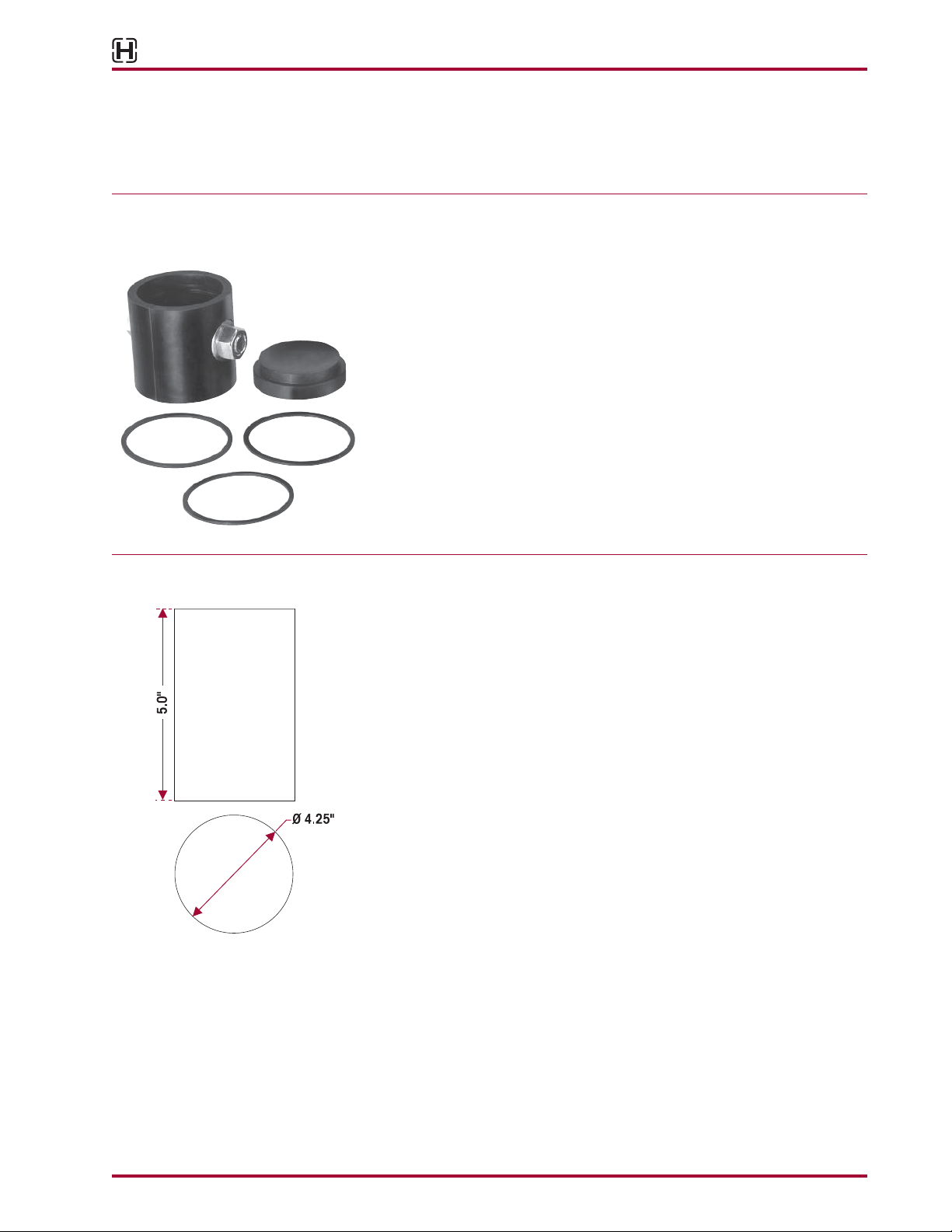
BAR PIN END BUSHING RECEIVING TOOL
This shop made tool is designed to receive bar pin end bushing. Bushing tool
is made from cold rolled steel or equivalent. Drawing is for reference only.
Hendrickson does not supply this tool.
'H
l!!J
C)C)
C)
l
i!::,
Iii
J
,,r
0
4.25"
Pro Gear and Transmission • 906 W. Gore St. Orlando, FL 32805 • 1 (877) 776-4600 / (407) 872-1901 • [email protected]
Parts Lists 8 17730-285
SECTION 5
Parts Lists
■ HN FR Series
ULTRA ROD®ULTRA ROD PLUS
®™
40
Torque Rod Assembly
45
1
8
5
54
7
16
17
6
9
53
10
2
5
3
19
20
18 54
26b
26a
20
21
20
21
15 14
13
12
11
12
23 25 24
23 25 24
22 22
20 19
13,14
28
29
30
31
45
31
32
27
4
33a,37a
33a,37a
34a
34a
35a
35a
35a
36a
36a
38
38
39
39
41
41
33b,37b
33b,37b
34b,37c
34b,37c
35b
35b
36b
36b
38
38
39
39
41
41
38
Location of
Auxiliary Spring
Part Number
40
40
38
40
----i
i --- ,
-r
--
j
\
.-e-<i>
----
: i
.
J,,._
_- I i
.
......
lj) i '
--
i !
I
)'
f . j [
·'
I
II\
.
.-
' . i
I ·
/,
1-·
\:
I
' i
/A
·I
!
>.
\1 I
I ' ·
Ii
I r).--r.
ii
·
i I I
t"--
I ii
,:
I
. I
;°
I I ! .j
I\
I
I :
:;
I I I I
II
. I
/·
· ' ·1
\.
I
I i I i ! I I
II
i
i '
I.
I II II '
' I I I
~
Ii
\:
I
//,·/~.,\
·/·
~11
1 I
I j
I.'
'i
\!
/ / i
1/·l
- n
··,\
~.;.-"''1
· .
I·
I\
I
__
-..--:::~
I . .I :
,\
. -
I
I:
I I __;,_:::-/_ I I I
I ' :I I
--'--:
-\J_: __, I '
. I I. - ®
L-
-
...
:.-Ii--,·_-<--
[ I I
I I
j/
I
--.l-t-'(1,
-lit
I
I·
·;
-1
-
--
,1
.--11
I
--
I
I .
--
j
\\
.
· I 1! - •
'1
, I
/
\,
\ - • •
l:
1
i t, -
_.
I I j
/
j!
\1\
\~
\i..J-
-4l
!
--
y
'I
(j
I
,_
'
.)~-\\
\
~
' ' /
\_.~
\
=
.-.-.
. I
~
•✓
\
',
,
~
' . I
/ ,.-.
-··\
\ :
.
·.
_
__..,
I
....
\''
__
1:-:-_:_
..
-
--
:rt-
-1
.--@c0---..
--
__
-,1.,<> '
~
-:i:bt~>
.
-....,,"\"""'.~,;.,--
$ >--
~
I
~
~
Pro Gear and Transmission • 906 W. Gore St. Orlando, FL 32805 • 1 (877) 776-4600 / (407) 872-1901 • [email protected]
HN®FR Series
17730-285 9 Parts Lists
KEY NO. PART NO. DESCRIPTION NO.REQ. KEY NO. PART NO. DESCRIPTION NO.REQ.
1 HN FR Saddle Assembly, See Figure 1 below 2
Includes Key Nos. 2-18
60686-0XX 16½", 17½", 18½" or 19"
58650-0XX 17½ or 22½"
60879-000L Bolster Spring Kit, One Side, (2 pcs),Includes
Key No. 2
2 *Bolster Spring 4
3 25114-011
7⁄16"-20 UNF 1.25" Bolt 32
4 48949-000
7⁄16"-20 UNF-2B Locknut 32
5 22962-027
7⁄16" Washer 64
6 Auxiliary Spring Assembly, See part no. 2
located on the component
60314-000 33⁄8" Height
65902-003 21⁄8" Height
7 58960-003 Auxiliary Spring Shim 6
8 58196-006 ½"-13 UNC-2A Round Head Square Neck Bolt 6
9 22962-011 ½" Washer 6
10 49846-000 ½"-13 UNC-2A Locknut 6
11 57878-003 Rebound Strap 2
60639-000 Anchor Plate Assembly, Includes Key Nos.12-14 4
12 *Anchor Plate 4
13 *½" Washer 8
14 *½"-13 UNC-2A Locknut 8
15 58948-001 Auxiliary Spring Mounting Plate 2
16 58949-000 Auxiliary Spring Mounting Plate Shim 2
(Inboard - ¼" thick)
17 22962-020 ½" Washer (Outboard - ¼" thick) 2
18 58343-001 Saddle Vee Bracket 2
58440-001 Vee Bracket Fastener Kit, One Side,
Includes Key Nos. 19-21
19 50764-006 ¾"-10 UNC-2A Hex Head Bolt 8
20 22962-001 ¾" Washer 16
21 49842-000 ¾"-10 UNC-2B Locknut 8
22 60680-003L Shock Absorber 4
23 22962-001 ¾" Washer 4
24 30585-000
5⁄8" Upper Shock Locknut 4
25 22962-004
5⁄8" Upper Shock Washer 4
26 Equalizing Beam Assembly 2
a 58494-002 54" Shim Type HN 482FR
a 59973-003 54" Shim Type HN 542FR / 582FR
a 59973-005 60" Shim Type HN 542FR / 582FR
b 57889-002 54" Shim Type HN 422FR
b 57889-005 52" Shim Type HN 422FR
27 Bar Pin End Bushing Service Kit, One Wheel End,
Includes Key Nos. 28-32
34013-087L Non-Shim Type
34013-088L Shim Type
34013-188L Rotating, Shim Type
28 *Bar Pin End Bushing 4
29 Bar Pin Shim 8
50130-000 0.19" /0.19"
50131-000 0.25"/0.12" (Not shown)
57026-000 0.375"
56659-001 Bar Pin Beam End Mounting Fastener Kit,
Axle Set, Includes Key Nos.30-32
30 48941-000 1"-8 UNC 6.0" Hex Bolt 8
31 22962-008 1" Hardened Washer 16
32 48942-000 1"-8 UNC Locknut 8
33 Two-Piece Longitudinal Torque Rod Kit,
Straddle/Straddle, Includes Tube End, Spacer End
a 60218-000 ULTRA ROD, 27" Max., Includes Key Nos. 35a
b 60223-000 ULTRA ROD, 35" Max., Includes Key Nos. 35a
34 **Two-Piece Transverse Torque Rod Kit,
Straddle/Taper, Includes Tube End,Spacer End
a 60215-000 ULTRA ROD, Includes Key Nos.35a-36a
b 65781-000 ULTRA ROD PLUS,Includes Key Nos.35b-36b
35 Straddle Bushing 2
a 47691-000H ULTRA ROD
b 64400-002L ULTRA ROD PLUS
36 Taper Bushing 2
a 64697-000H ULTRA ROD
b 64400-004L ULTRA ROD PLUS
37 **One-Piece Torque Rod Assembly, Includes
Bushings,See selection guide on page 10
a ULTRA ROD
b ULTRA ROD PLUS Straddle/Straddle
c ULTRA ROD PLUS Straddle/Taper
38 Torque Rod Frame Bracket 4
22186-000 43⁄8"
46015-000 5¼"
39 Backup Plate 2
45045-003 43⁄8"
46869-005 5¼"
40 Torque Rod Shim, See selection guide 8
on page 10
41 ***Transverse Rod Axle Bracket 2
NOTE: Equalizing beam axle brackets for drive axles are supplied by the axle manufacturer.
* Item included in assembly/kit only, part not sold separately.
** Transverse rods are mandatory for HN Suspension regardless of axle spacing. See Literature No. 59310-004 for more information.
Hendrickson’s part number is stamped on the rod for identication. Be sure and include sufx number when ordering,this number indicates rod
length.The Hendrickson 2-piece ULTRARODS®can be used to create the desired length, see Torque Rod Selection Guide Literature No.45745-148.
*** Not supplied by Hendrickson, used for reference only. Refer to vehicle manufacturer for more information. Hendrickson is not responsible for components
supplied by vehicle manufacturer. For assistance with maintenance and rebuild instructions on these components, see vehicle manufacturer.
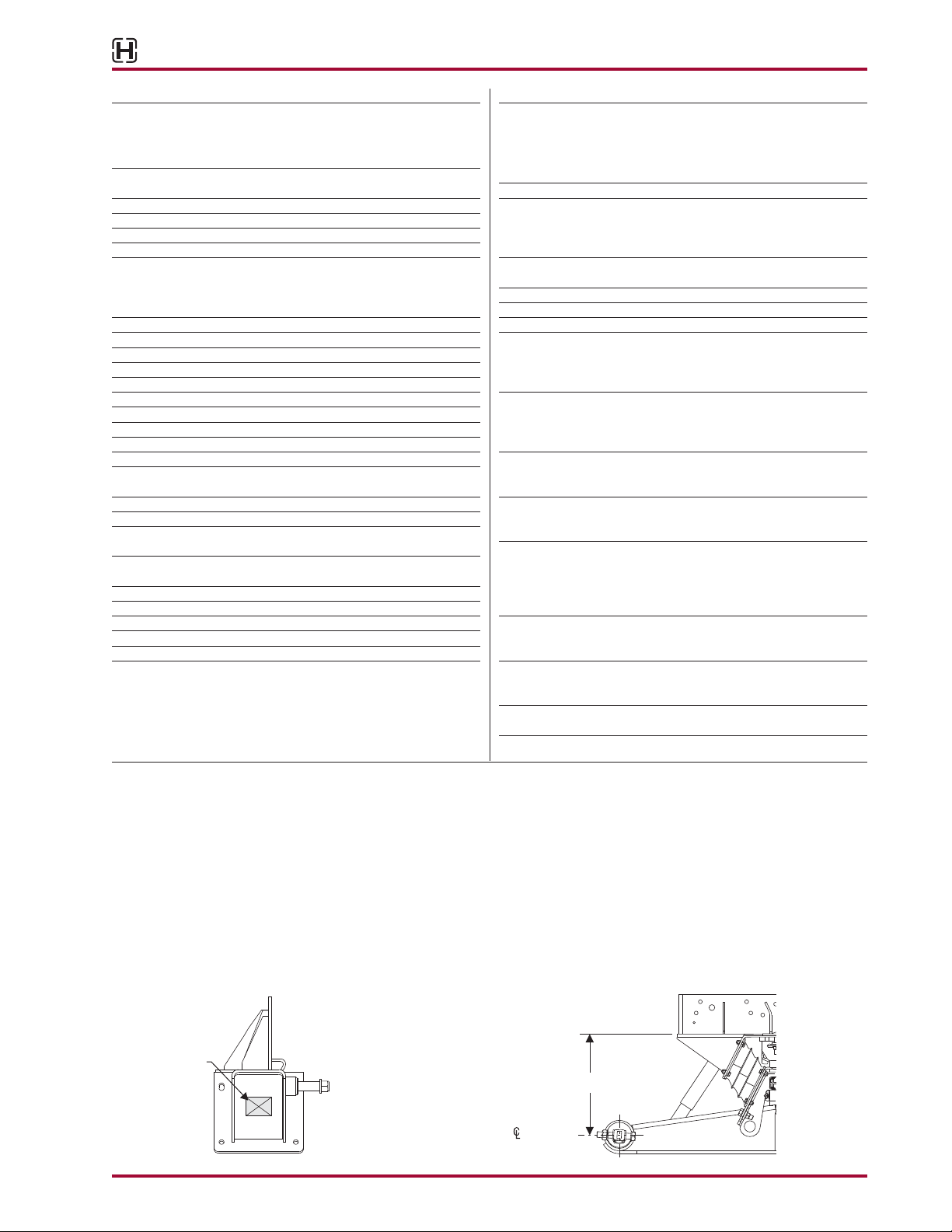
FIGURE 1
SADDLE ASSEMBLY (KEY NO. 1)
Bottom of Frame
of End Hub
Saddle Height
SIDE VIEW
Location of
Saddle Assembly
Part Number
Locate the part number on the saddle assembly
If the saddle assembly number is not legible or available,have the VIN number and
saddle height (for part verification) and contact vehicle manufacturer for part number.
Questions? Contact Hendrickson Truck Parts
OR
'H
l!!J
=====================-
=====================-
=====================-
e
u------1
e
Pro Gear and Transmission • 906 W. Gore St. Orlando, FL 32805 • 1 (877) 776-4600 / (407) 872-1901 • [email protected]
HN®FR Series
Parts Lists 10 17730-285
■ SELECTION GUIDE
ONE PIECE TORQUE ROD ASSEMBLY
Longitudinal Torque Rod Transverse Torque Rod
Key No. 37a Key No. 37b Key No. 37c
ULTRA ROD
Straddle/Straddle Assembly
ULTRA ROD PLUS
Straddle/Straddle Assembly
ULTRA ROD PLUS
Straddle/Taper Assembly
Length Part No. Capacity Length Part No. Capacity Length Part No Capacity
22.83" 62001-580 HN 422FR 19.49" 72100-495 HN 542FR/582FR 19.69" 72950-500 HN 522
23.82" 62000-605 HN 482FR 22.05" 72100-560 HN 522 19.88" 72950-505 HN 522
28.15" 62000-715 HN 422FR 23.03" 72100-585 HN 542FR/582FR 24.02" 72350-610 HN 542FR
29.13" 62001-740 HN 482FR 23.62" 72400-600 HN 542FR 24.02" 72950-610 HN 542FR/582FR
25.00" 72100-635 HN 542FR/582FR 24.21" 72950-615 HN 542FR/582FR
26.97" 72100-685 HN 522 24.41" 72350-620S HN 422FR/482FR
28.54" 72100-725 HN 542FR/582FR 25.43" 72350-630S HN 422FR
28.94" 72401-735 HN 542FR
TORQUE ROD SHIMS
Key No. 40
Part No. Shim Thickness Shim Length Fasteners
49689-000 0.060" 43⁄8" ¾" and 5⁄8" Fasteners
49689-001 0.080"
65640-002 0.060" 5¼" ¾" and 5⁄8" Fasteners
65640-003 0.120"
67779-002 0.060" 5¼" 7⁄8" Fasteners
67779-003 0.120"
'H
l!!J
Pro Gear and Transmission • 906 W. Gore St. Orlando, FL 32805 • 1 (877) 776-4600 / (407) 872-1901 • [email protected]

HN®FR Series
17730-285 11 Preventive Maintenance
SECTION 6
Preventive Maintenance
Hendrickson recommends that preventive maintenance be performed on a regular basis to
help ensure all components function to their highest efficiency. Proper preventive maintenance
programs can also help control repair costs and eliminate downtime.All new equipment should
undergo an initial pre-service inspection,and be inspected at the following intervals.
HENDRICKSON RECOMMENDED
PREVENTIVE MAINTENANCE INTERVALS
■ PRE-DELIVERY INSPECTION
1. Visually inspect suspension for proper assembly.
2. Check all fasteners for proper torque with special attention to the equalizing beam end
connections.
3. Set auxiliary spring shims to required specifications, the number of shims is dependent on
the following criteria:
■ Vehicle empty weight
■ Vehicle application
■ Roll stability versus ride requirements
4. Verify the lateral alignment of axles are within the vehicle manufacturer’s tolerances (con-
sult the applicable vehicle manufacturer’s instructions).
■ INSPECTION AT ONE (1) MONTH
1. Visually inspect suspension components, check for:
■ Proper suspension function
■ Signs of unusual movement,loose or missing components
■ Signs of abrasive or adverse contact with other components
■ Damaged, bent or cracked parts
2. Check all fasteners for proper torque with special attention to the equalizing beam end
connections.
■ PREVENTIVE MAINTENANCE
1. Every three months inspect auxiliary springs and bolster springs.
2. Every six months inspect equalizing beam end connections and Torque rods.
3. Every twelve months:
a. Visually inspect suspension for proper assembly
b. Check all fasteners for proper torque with special attention to the equalizing beam end
connections.
c. Verify the lateral alignment of axles are within the vehicle manufacturer’s tolerances
(consult the applicable vehicle manufacturer’s instructions)
d. Visually inspect suspension components. Check for all of the following and replace
components as necessary:
■ Proper suspension function
■ Signs of unusual movement,loose or missing components
■ Signs of abrasive or adverse contact with other components
■ Damaged, bent or cracked parts
'H
l!!J
Pro Gear and Transmission • 906 W. Gore St. Orlando, FL 32805 • 1 (877) 776-4600 / (407) 872-1901 • [email protected]
HN®FR Series
Preventive Maintenance 12 17730-285
SAFETY REMINDER
All applicable warnings and cautions should be read carefully to help prevent personal injury
and to assure that proper methods are used. Improper maintenance, service or repair may
damage the vehicle, cause personal injury, render the vehicle unsafe in operation, or void
manufacturer’s warranty.
Failure to follow the applicable safety precautions can result in personal injury and/or property
damage. Carefully read and understand all safety related information within the applicable
Hendrickson publications,on all decals and those provided by the vehicle manufacturer before
operating the vehicle, or conducting any maintenance, service or repair.
OVERLOADED SUSPENSIONS CAN CAUSE COMPONENT FAILURE, LOSS OF VEHICLE CONTROL,
SEVERE PERSONAL INJURY OR DEATH.
• DO NOT EXCEED SUSPENSION CAPACITY RATINGS.
• DO NOT OPERATE AUXILIARY LIFT AXLES OR OTHER LOAD TRANSFERRING DEVICES IN ANY WAY
THAT CAN OVERLOAD THE SUSPENSION.
COMPONENT INSPECTION
The following inspection should be performed at recommended maintenance intervals.Visually
inspect all parts of the suspension for signs of wear, damage or movement. Look for bent or
cracked parts.Replace all worn or damaged parts.
IMPORTANT NOTE Replace all worn or damaged parts.
■ Auxiliary spring and Bolster spring — See Auxiliary Spring Assembly and Bolster Springs
in this section.
■ Equalizing beam assembly — Check the overall condition of the equalizing beam for
cracks,dents,dings,or other damage on the outer edges of the beam.Check the beam end
connections every six months for tearing or extreme bulging.Check for any metal-to-metal
contact in the bushed joints. Replace all worn or damaged parts.
■ Fasteners — All fasteners must be inspected at pre-delivery,after the first month,and every
twelve months thereafter. Look for any loose or damaged fasteners on the entire suspen-
sion. Make sure all fasteners are tightened to a torque value within the specified torque
range. See Torque Specification Section of this publication for Hendrickson recommended
torque requirements. Use a calibrated torque wrench to check torque in the tightening
direction.As soon as the fastener starts to move, record the torque. Correct the torque if
necessary. Replace any worn or damaged fasteners.
NOTE Hendrickson recommends the use of Grade 8 bolts,Grade C locknuts and hardened washers for
all suspension component attachments.
■ Saddle assembly — Check all attaching fasteners for proper torque.Visually inspect the
saddle for signs of movement on the frame rail or damage and welds for cracks.Inspect the
area around the saddle gussets for cracks.
■ Torque rods — All torque rods should be inspected every six months.Check for wear,dam-
age and proper function.Visually inspect for signs of unusual movement,loose,or missing
fasteners.The torque rods must be connected and in good working condition when operat-
ing the vehicle.
■ Vee Bracket — Raise the vehicle frame and visually inspect the Vee bracket for wear or
damage. Look for excessive wear or cracks on the Vee bracket’s auxiliary spring contact
surface. Replace all worn or damaged parts.
■ Wear and Damage — Inspect all parts of the suspension for wear and damage. Look for
bent or cracked parts.Replace all worn or damaged parts.
See vehicle manufacturer’s applicable publications for other preventive maintenance requirements.
'H
l!!J
A
WARNING
Pro Gear and Transmission • 906 W. Gore St. Orlando, FL 32805 • 1 (877) 776-4600 / (407) 872-1901 • [email protected]
HN®FR Series
17730-285 13 Preventive Maintenance
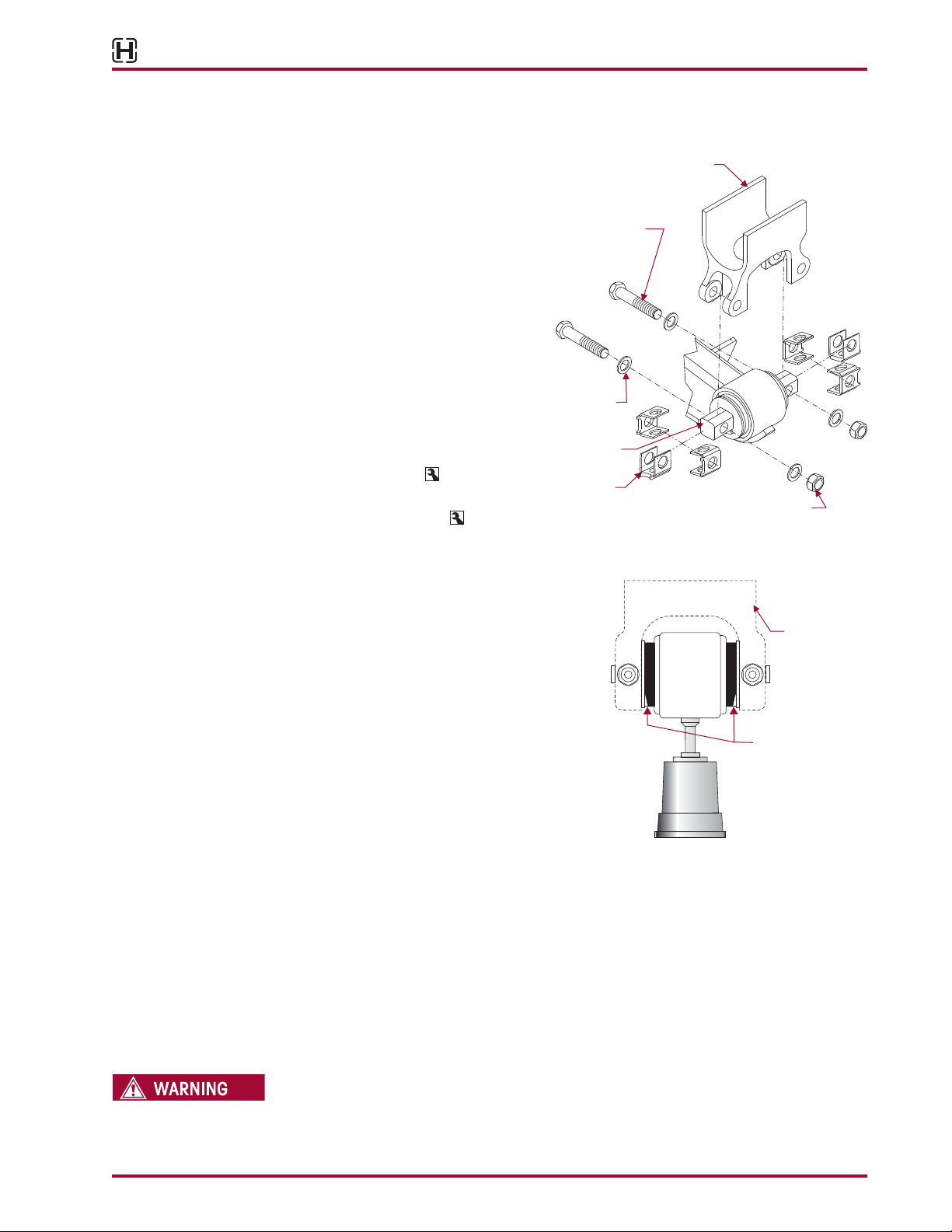
EQUALIZING BEAM END CONNECTION
FIGURE 6-1
The equalizing beam end connection
for the HNFR is bar pin style with a
rubber bushing and alignment shims
as shown in Figure 6-1.An inspection
of the equalizing beam end connec-
tion is necessary when a vehicle is in
the shop for major repair work or every
six months,whichever comes first.
This equalizing beam end connection
requires that the fasteners are kept
tight to maintain the clamp load of
the axle bracket legs to the bar pin.All
bushing motion is accommodated by
rubber deflection.Tighten the equaliz-
ing beam 1" end fasteners to:
■ At the locknut to 450-600 foot
pounds torque, or
■ At the bolt head to 500-650
foot pounds
FIGURE 6-2
INSPECTION
1. Chock the wheels.
2. Visually inspect suspension components for
signs of movement or excessive wear.
a. Inspect alignment shims in equalizing
beam end for looseness. Lightly tap on
the alignment shims to see if they can
be moved.
b. Inspect equalizing beam end connec-
tion for signs of excessive wear or loose-
ness.An equalizing beam end connec-
tion, which is visibly cleaner than the
other connections,may indicate a loose connection.
c. Look for worn, frayed, or distorted rubber in the equalizing beam end bushing.
d. Look for the equalizing beam to be lower in the beam hanger.
e. The gap on each side of the visible rubber at the lower end of the end bushing is
normal and not an indication to replace the bushing, see Figure 6-2. Because all rub-
ber end bushings are in compression,with the load bearing on the top side, the lower
side of the rubber is slightly relieved, allowing the rubber to move inward, and a gap
appears.
f. Place a jack under each equalizing beam end as shown. Raise the jack to check for
movement in the connection or rubber components, see Figure 6-2.
IF BAR PIN MOVEMENT OR LOOSENESS IS NOTED IN THE EQUALIZING BEAM END HUB, DO NOT
OPERATE THE VEHICLE. REPLACE THE RUBBER END BUSHINGS AND ALL CONNECTING PARTS.
THE ABOVE CONDITION CAN RESULT IN COSTLY REPAIR, DOWNTIME, POSSIBLE SEPARATION OF
COMPONENTS, LOSS OF VEHICLE CONTROL, PROPERTY DAMAGE, OR PERSONAL INJURY.
Axle Bracket
Supplied by vehicle
manufacturer
1" Locknut
Tightening Torque
450-600 ft. lbs.
1" Washer
1" Bolt
Tightening Torque
500-650 ft. lbs.
Bar Pin
Alignment
Shim
Bar Pin
Gap in rubber of
Bar Pin End Bushing
is normal
Axle Bracket
Supplied by
Vehicle
Manufacturer
'H
l!!J
~
,-
-
--
---------------
1
I I
' '
i ,----------
---,
}
:
//
~----._
'\
:,
\_
,,.,,
I \
\I
I I
~~ ~~
I I
I I
~
----
-)
A
WARNING
Pro Gear and Transmission • 906 W. Gore St. Orlando, FL 32805 • 1 (877) 776-4600 / (407) 872-1901 • [email protected]
HN®FR Series
Preventive Maintenance 14 17730-285
3. If bar pin movement or looseness is detected in the equalizing beam end hub, DO NOT
operate vehicle.Replace the equalizing beam end bushings and all connecting parts.Refer
to the Component Replacement Section of this publication.
4. Check and record torque values, as received, for each 1" bar pin fastener. Correct torque
values as required making sure all fasteners are tightened to:
■ At the locknuts to 450-600 foot pounds torque or
■ At the bolt head to 500-650 foot pounds
5. Recheck equalizing beam end connections for signs of looseness.
■ Inspect alignment shims in equalizing beam end for looseness. Lightly tap on the
alignment shims to see if they can be moved.
■ Inspect equalizing beam end connection for signs of excessive wear or looseness.
NOTE An equalizing beam end connection, which is visibly cleaner than the other connections, may
indicate a loose connection.
6. If bar pin looseness is still detected in the equalizing beam end hub, DO NOT operate the
vehicle. One or more components will require replacement, see Component Replacement
Section of this publication.
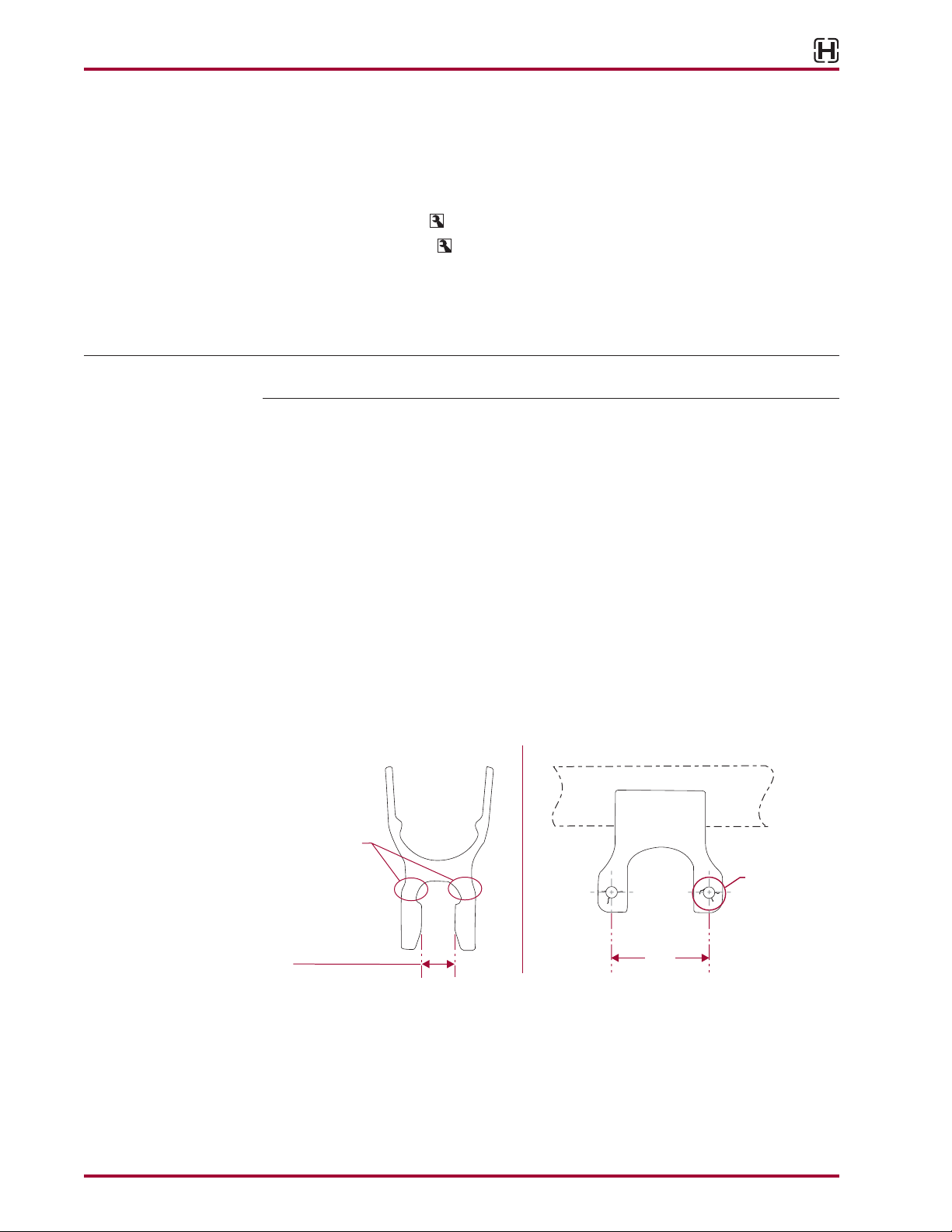
AXLE BRACKETS
The axle brackets are furnished and welded into position by the vehicle or axle manufacturer.
■ When inspecting the equalizing beam end connection also inspect the axle brackets for
damage or cracks,see Figure 6-3.Measure the dimension as shown in Figure 6-3,any axle
bracket that is found damaged or cracked must be repaired or replaced.Consult the vehicle
manufacturer for inspection, component repair and replacement instructions.
■ When an equalizing beam is removed for repair, or an inspection of the equalizing
beam end connection reveals movement, measure the distance between the axle bracket
legs for correct width. Refer to Figure 6-4 for measurement location and dimensions.An
axle bracket outside of the measurement range must be repaired or replaced.Consult the
vehicle manufacturer for inspection, component repair and replacement instructions.
FIGURE 6-3 FIGURE 6-4
8.5"
(216 mm)
2.313" (58.74 mm)
2.263" (57.48 mm)
Axle Bracket* Leg Dimensions Axle Bracket* Leg
Look for craks
in these locations
Axle
Typical
Crack
*Typical axle bracket shown
'H
l!!J
,~---------------------
1 I
I
I I
I
,
_____
_
~
___J
Pro Gear and Transmission • 906 W. Gore St. Orlando, FL 32805 • 1 (877) 776-4600 / (407) 872-1901 • [email protected]
HN®FR Series
17730-285 15 Preventive Maintenance
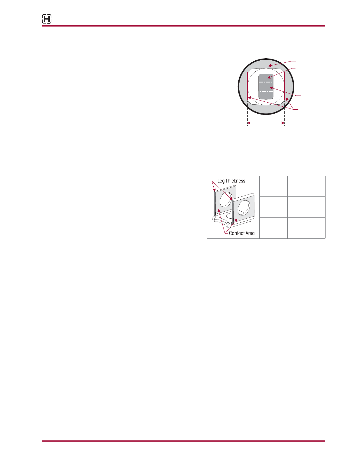
BAR PIN END BUSHING
FIGURE 6-5
An indication that the bar pin end bushing requires
replacement is when one or more of the following
conditions apply:
■ Visual inspection of contact area (the flat face
area where bar pin contacts the axle bracket) on
the bar pin reveals signs of excessive wear. If the
thickness of the bar pin in the contact area mea-
sures less than 1.874" (47.59 mm), bar pin end
bushing requires replacement, see Figure 6-5.
■ Visual inspection of the bolt holes in the bar
pin reveals signs of elongation or wear, see
Figure 6-5.
BAR PIN SHIM
FIGURE 6-6
An indication that the bar pin shims
require replacement is when one or
more of the following conditions apply:
■ Visual inspection of contact area
on the shim reveals signs of exces-
sive wear.
■ The thickness of any single leg on
the shim, is less than the measure-
ment shown in Figure 6-6,replacement of bar pin shim is required.
BOLSTER SPRINGS
Inspect all four bolster springs on a periodic basis.Actual bolster spring service condition and
performance may vary depending upon suspension and vehicle configuration, operation,
service and other factors.The following inspection guidelines are intended to assist vehicle
operators and maintenance personnel in examining the bolster springs and determining when
replacements may be needed. In the event one bolster spring on one equalizing beam assem-
bly shows signs of damage or excessive wear, Hendrickson recommends that both bolster
springs installed on that equalizing beam assembly be replaced.When the bolster springs are
replaced on one side only, the vehicle may lean slightly.The new bolster springs will tend to
settle to some degree,and return the vehicle to its original condition.The following procedure is
recommended for proper inspection.
1. Chock the front wheels to prevent movement of the vehicle during inspection of the
suspension.
2. Raise rear of vehicle approximately 4.0" - 5.0", (102 mm - 127 mm) just prior to lifting
wheels off ground, and support with stands.
3. Inspect all bolster springs using the following criteria. If cuts, splits, or bonding separation
are detected in the rubber, measure the depth of the damaged area using a six-inch ma-
chinist scale to determine if replacement is required.
■ Bent, burred or overhanging edges of the bolster spring metal plates may occur due
to mishandling in service. If the rubber is not trapped, and there are no sharp metal
edges in contact with the free surface of the rubber, this condition is acceptable.
■ Creases formed by folding of the rubber surface under load are acceptable.These creases
appear as stripes on the surface, polished by wear or covered with tacky rubber.
Bar Pin Mount
If bar pin measurement is less than
1.874" (47.59 mm), component
replacement is required.
1.874"
(47.59 mm)
Rubber
Contact Area
Bolt Hole
Thickness
of
Shim Leg
Minimum
Thickness
Required
1⁄8"0.123" (3.1 mm)
3⁄16"0.186" (4.7 mm)
¼" 0.248" (6.3 mm)
3⁄8"0.371" (9.4 mm)
'H
l!!J
I I
I I
~
------.1
Pro Gear and Transmission • 906 W. Gore St. Orlando, FL 32805 • 1 (877) 776-4600 / (407) 872-1901 • [email protected]
HN®FR Series
Preventive Maintenance 16 17730-285
■ Minor oil and grease contamination in the rubber due to vehicle operation is accept-
able. A slight change in shape of the rubber due to permanent set should not be
mistaken for oil and grease contamination. Certain softening of the rubber surface is
acceptable. However, unacceptable swelling due to contamination will require bolster
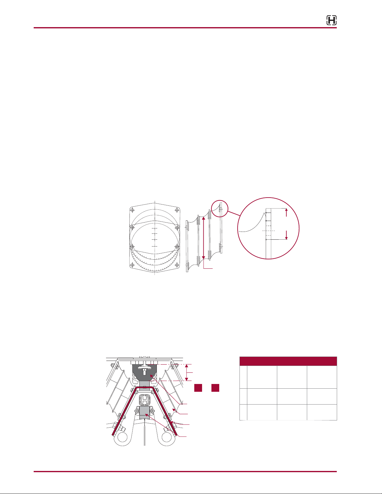
spring replacement.Measure bolster springs in the unloaded state.If the rubber diam-
eter of the bolster spring exceeds 8¾" (222.3 mm),see Figure 6-7,then bolster spring
replacement is necessary.
■ Cuts or Splits in the rubber of over 3.0" (76 mm) in length and an average depth of
1.0" (25.4 mm) are not acceptable and require bolster spring replacement. In par-
ticular, look for signs of cuts or splits in the rubber at points indicated in Figure 6-7 as
“///////”.
■ Bonding separation of the rubber from a bonded metal surface to a depth of up to
1½" (38 mm) is acceptable. If any bonding separation is more than 1½" (38 mm)
deep, both bolster springs should be replaced on the affected side of the vehicle (see
Figure 6-7). An unloaded bolster spring may be inspected for any bonding separa-
tion by measuring at points indicated in Figure 6-7 as “///////”. Any thin film or other
residual rubber material on the metal plates resulting from the molding process may
be ignored during inspection.
FIGURE 6-7
8¾" (222.25 mm) Maximum
1½"
(38 mm)
AUXILIARY SPRING ASSEMBLY
A visual inspection of the auxiliary spring is required every three months. It is acceptable to
have some scuffing on the bottom edges of the auxiliary spring due to contact with the bolster
springs and/or Vee bracket. If the auxiliary spring is damaged, replace the auxiliary spring as
outlined in the Component Replacement Section of this publication. See the following chart
for the new unloaded auxiliary spring height. If the minimum unloaded height decreases than
shown in the chart replacement is required, see Figure 6-8.
FIGURE 6-8
Auxiliary Spring
Part
Number
Unloaded
Height
Minimum
Unloaded
Height
A60314-000 33⁄8"
(85.7 mm)
3.0"
(76 mm)
B65902-003 21⁄8"
(53.9 mm)
115⁄16"
(49.2 mm)
Minimum
Height Unloaded
Auxiliary Spring
Rebound Strap
Bolster Spring
Vee Bracket
AB
or
'H
l!!J
■
■
Pro Gear and Transmission • 906 W. Gore St. Orlando, FL 32805 • 1 (877) 776-4600 / (407) 872-1901 • [email protected]
HN®FR Series
17730-285 17 Preventive Maintenance
REBOUND STRAP
Periodic inspection of the rebound strap, see Figure 6-8, is required every six (6) months. If the
rebound strap is torn, frayed, or not intact replace as outlined in the Components Replacement
Section of this publication.
LONGITUDINAL AND TRANSVERSE TORQUE RODS
HNFR SUSPENSIONS INCORPORATE TRANSVERSE RODS FOR VEHICLE STABILITY. IF THESE
COMPONENTS ARE DISCONNECTED OR ARE NON-FUNCTIONAL,THE VEHICLE SHOULD NOT BE
OPERATED. FAILURE TO DO SO CAN RESULT IN ADVERSE VEHICLE HANDLING, LOSS OF VEHICLE
CONTROL, POSSIBLE TIRE CONTACT WITH THE FRAME, PREMATURE COMPONENT DAMAGE, OR
SEVERE PERSONAL INJURY.
All torque rods need to be inspected for looseness by one of the following methods.
■ Method 1 — For Tractor applications only with brakes applied, slowly rock the empty
vehicle with power while a mechanic visually checks the action at both ends.
■ Method 2 — with the vehicle shut down, a lever check can be made with a long pry bar
placed under each rod end and pressure applied.
Visually inspect torque rod bushings for torn or shredded rubber, inspect for bent, cracked, or
broken torque rods and also for end hubs that have an elongated “oval” shape.Any of these
conditions require component replacement.
The length of the torque rods is determined by the truck manufacturer for optimum drive line
angle and alignment.The longitudinal torque rods control pinon angles and also absorb accel-
eration and braking forces.The transverse torque rods control the side to side inputs such
as cornering.The mounting brackets at the axle ends of the torque rods are furnished and
welded into position on the axle housings by vehicle manufacturer or the axle manufacturer.A
two-piece torque rod is also available to cut and weld to the desired length, see Hendrickson
publication 45745-148.
Straddle mount torque rod end attaching fasteners are furnished by the vehicle manufacturer.
It is important that the tightening torque of the locknuts be checked during preventive mainte-
nance service. Follow the vehicle manufacturer’s specifications for torque values.
NOTE Hendrickson Suspension recommends Grade 8 bolts, hardened flat washer and Grade C
locknuts be used for all straddle mount torque rod attachments.
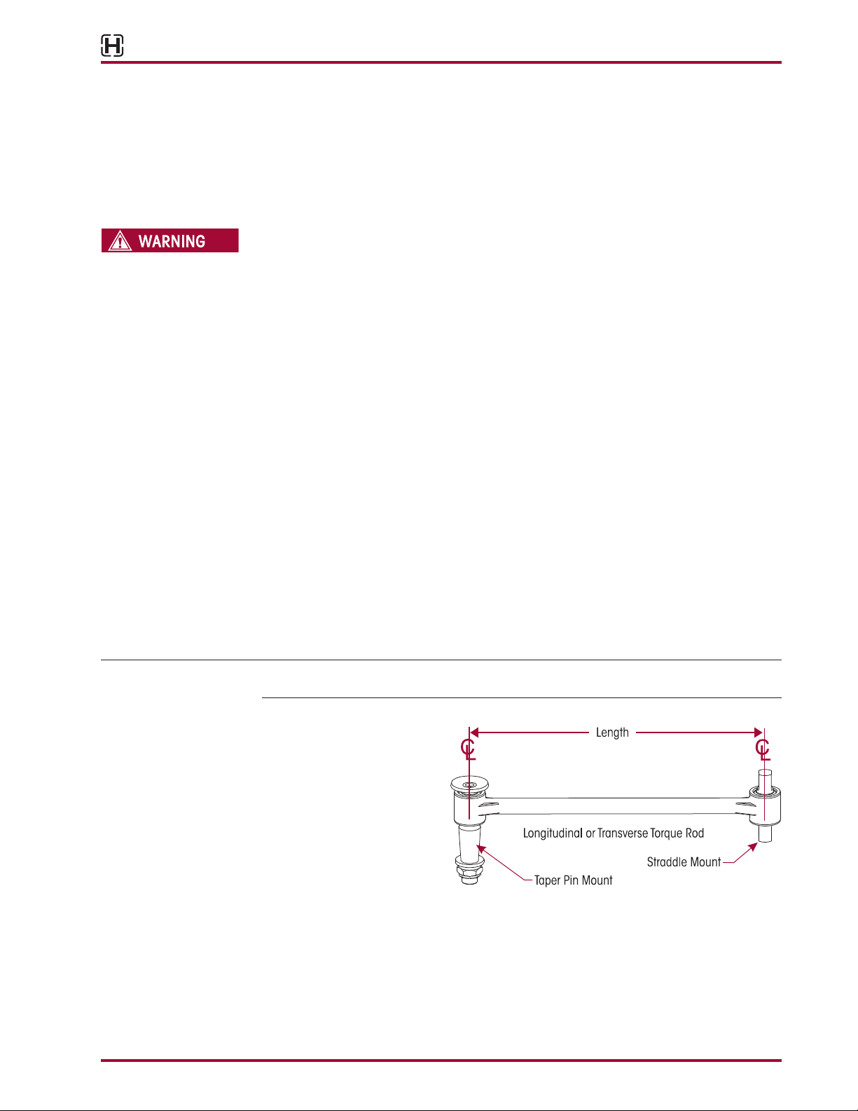
FIGURE 6-9
The longitudinal rod is strad-
dle/straddle mount, and the
transverse rod it straddle
mount / taper pin mount, as
shown in Figure 6-9.
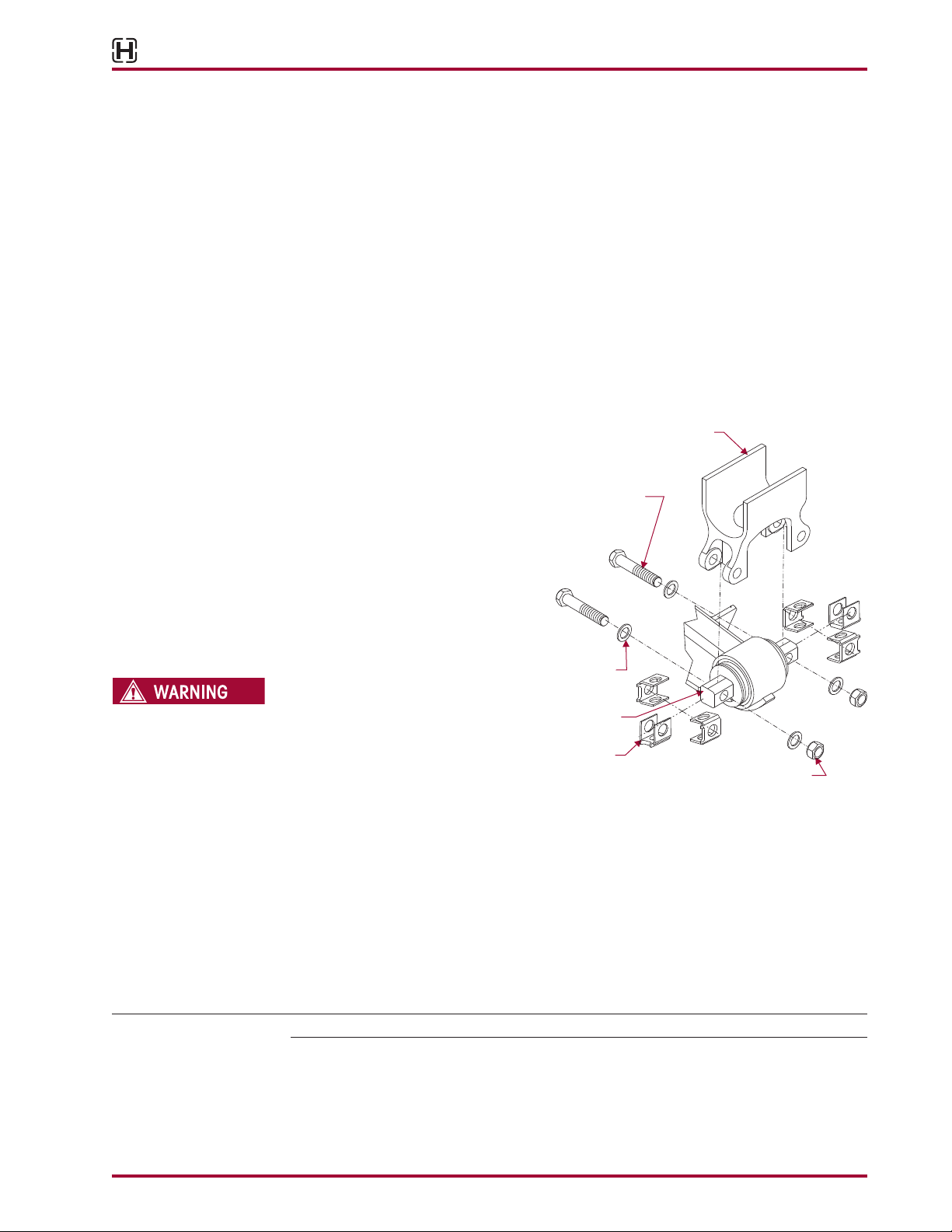
Whether the bushings are
straddle mount or taper pin
mount, (see Figure 6-9) they
can be replaced by press-
ing out the worn bushing and
installing a new genuine Hendrickson bushing. Refer to the technical procedure for the proper
replacement instructions for your specific suspension system.
'H
l!!J
A
WARNING
Longitudinal
or
Transverse
Torque
Rod
Straddle
Mount
_/
Taper
Pin
Mount
Pro Gear and Transmission • 906 W. Gore St. Orlando, FL 32805 • 1 (877) 776-4600 / (407) 872-1901 • [email protected]
HN®FR Series
Alignment & Adjustments 18 17730-285
SECTION 7
Alignment & Adjustments
DRIVE AXLE ALIGNMENT INSPECTION PROCEDURE
Proper alignment is essential for maximum ride quality, performance, and tire service life.The
following recommended alignment procedure as described below, should be performed if
excessive or irregular tire wear is observed.
NOTE Proper vehicle alignment can only be achieved when all axles are aligned to the vehicle’s
centerline and the steering axle’s caster, camber and toe-in settings are within specifications.
If, however, axle alignment equipment is not available the alignment of the drive axles may be
checked by performing the following steps.
1. Use a work bay with a level, flat surface.
2. Relax the suspension by slowly moving the vehicle back and forth several times in a straight
line without using the brakes.This will slacken or loosen the suspension as the vehicle is
positioned. End with all wheels positioned straight ahead.
3. DO NOT set the parking brake.Chock the front wheels of the vehicle.
4. Verify and maintain the air system at full operating pressure.
5. Verify all suspension components are in good condition. Repair or replace any worn or
damaged suspension components before proceeding with the alignment process.
6. Ensure all drive axle tires are the same size.
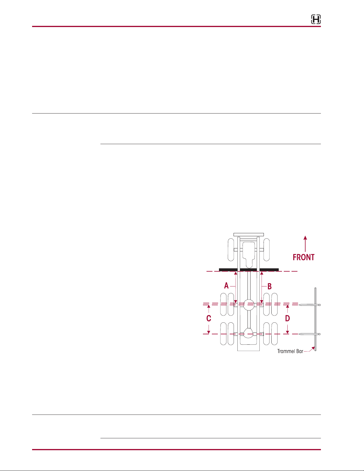
FIGURE 7-1
7. Securely clamp a six-foot piece of
STRAIGHT bar stock or angle iron
across the lower frame flange as
shown in Figure 7-1. Select a loca-
tion for the bar stock or angle iron
as far forward of the drive axle as
possible where components will not
interfere.
8. Accurately square the bar stock or
angle iron to the frame using a car-
penter’s square.
9. Using a measuring tape, measure
from the straight edge to the forward
face of the front drive axle arms on
both sides of the vehicle as shown in
Figure 7-1, Aand B.
10. Calculate the difference between measurements Aand B.
a. If the front drive axle is within vehicle manufacturer’s specifications, proceed to check
the rear drive axle (Step 11).
b. If alignment of the front drive axle IS NOT within the vehicle manufacturer’s specifica-
tions, then the alignment of this axle MUST be corrected BEFORE measuring the rear
drive axle alignment (Step 11).Correct the alignment of this axle by following the bar
pin alignment instructions.
NOTE Since the remaining drive axle will be aligned relative to the front drive axle, it is essential
that the front drive axle is aligned within the vehicle manufacturer’s specifications prior to the
alignment of the remaining drive axle.
'H
l!!J
t
FRONT
Trammel
Bar
Pro Gear and Transmission • 906 W. Gore St. Orlando, FL 32805 • 1 (877) 776-4600 / (407) 872-1901 • [email protected]
HN®FR Series
17730-285 19 Alignment & Adjustments
11. Using a trammel bar,measure the distance from the spindle center of the front drive axle to
the spindle center of the rear drive axle on both sides of the vehicle;see Figure 7-1,Cand D.
12. Calculate the difference between measurements Cand D.
a. If the measurements are within the vehicle manufacturer’s specifications,then the rear
drive axle alignment is acceptable.
b. If alignment of the rear drive axle IS NOT within the vehicle manufacturer’s specifica-
tions,then the alignment of this axle MUST be corrected. Correct the alignment of this
axle by following the bar pin alignment instructions.
13. Recheck measurements to confirm adjustments. Repeat Steps 9 through 12 until the cor-
rect alignment is achieved.
14. When all drive axle alignments are within the vehicle manufacturer’s specifications then
the alignment procedure is complete.
BAR PIN ALIGNMENT
FIGURE 7-2
The alignment feature consists of
specially designed, tightly tolerance
steel shims which fill the 3⁄8" (9.5 mm)
total gap between the bushing’s bar
pin and the axle bracket legs.The gap
must be filled by placing the shims on
the bushing assembly in one of the
positions shown in Figure 7-2 or 7-3.
Hendrickson has three shim designs
options for alignment, part number
50130-000 (provided), 50131-000
and 57026-000, see Figure 7-5.
A BAR PIN SHIM MUST BE INSTALLED AT
EACH BOLT LOCATION.THE SAME PART
NUMBER SHIM INTHE SAME ORIENTATION
MUST BE USED AT BOTH BOLT LOCATIONS
ON ANY ONE END BUSHING. DO NOT
INSTALL OR STACK MORETHAN ONE SHIM
AT EACH BOLT LOCATION. USE GENUINE
HENDRICKSON BAR PIN SHIMS, DO NOT
USE STANDARD WASHERS.FAILURE TO FOLLOWTHESE WARNINGS MAY RESULT IN IMPROPER VEHICLE
ALIGNMENT, FRACTURE OF THE AXLE BRACKET OR BAR PIN WHICH COULD RESULT IN THE LOSS OF
VEHICLE CONTROL AND POSSIBLE PERSONAL INJURY OR PROPERTY DAMAGE.
ALIGNMENT ADJUSTMENT
If alignment of the drive axles is required, as determined by an alignment inspection procedure,
the following steps will need to be performed.
1. Determine direction of axle thrust angle. Figure 7-4 illustrates the forward drive axle with a
thrust angle to the left (-negative thrust).
SERVICE HINT Axle movement is in the same direction as the increased shim thickness, see Figure 7-3.
Axle Bracket
Supplied by vehicle
manufacturer
1" Locknut
Tightening Torque
450-600 ft. lbs.
1" Washer
1" Bolt
Tightening Torque
500-650 ft. lbs.
Bar Pin
Alignment
Shim
Bar Pin
'H
l!!J
~/i
,
·,,.,,.-;,-y'
~
' ·,.
WARNING
Pro Gear and Transmission • 906 W. Gore St. Orlando, FL 32805 • 1 (877) 776-4600 / (407) 872-1901 • [email protected]
This manual suits for next models
4
Table of contents


