2
Safety Precautions
WARNING: TO REDUCE RISK OF FIRE OR ELECTRIC SHOCK,
DO NOT EXPOSE THIS APPARATUS TO RAIN OR
MOISTURE. NO OBJECTS FILLED WITH LIQUIDS,
SUCH AS VASES, SHALL BE PLACED ON THE
APPARATUS.
IMPORTANT SAFEGUARDS
Electrical energy can perform many useful functions. This unit has
been engineered and manufactured to assure your personal safety.
But IMPROPER USE CAN RESULT IN POTENTIAL ELECTRIC
SHOCK OR FIRE. In order not to defeat the safeguards incorporated
into this product, observe the following basic rules for its installation,
use, and service. Please read these “IMPORTANT SAFEGUARDS”
carefully before use.
All the safety and operating instructions should be read before the
product is operated.
The safety and operating instructions should be retained for future
reference.
All warnings on the product and in the operating instructions
should be adhered to.
All operating instructions should be followed.
•
•
•
•
Warning: This is a class A product. In a domestic environment this
product may cause radio interference in which case the
user may be required to take adequate measures.
Before connecting other products such as VCR’s and personal
protection against electric shock.
Do not use attachments not recommended by the
manufacturer as they may be hazardous.
When replacement parts are required, be sure the service
manufacturer or equivalents. Unauthorized substitutions may
Upon completion of any service or repairs to this product,
ask the service technician to perform safety checks to
determine that the product is in proper operating condition.
•
•
•
•
Under the following conditions,
1. Turn off the power.
2. Unplug this product from the wall outlet.
3. Refer service to qualified service personnel.
a) When the product emits smoke or unusual smell.
b) When the product exhibits a distinct change in performance
—for example, no picture or no sound.
c) If liquid has been spilled, or objects have fallen on the product.
d) If the product has been exposed to rain or water.
e) If the product has been dropped or damaged in any way.
f) When the power supply cord or plug is damaged.
Do not install this product in the following places:
in a damp or dusty room
where the product is exposed to soot or steam, such as
near the cooking counter or a humidifier
near heat sources
where condensation easily occurs, such as near the window
in a location exposed to direct sunlight or strong light
Do not place this product on an unstable cart, stand, or table.
The product may fall, causing serious injury to a child or adult,
and serious damage to the product.
The product should be mounted according to the
manufacturer’s instructions, and should use a mount
recommended by the manufacturer.
Do not use this product near water.
Be sure to install the product in the place where proper
temperature and humidity are kept ( “Operating conditions”
on page 19).
This product becomes hot during its use. Take enough care
when handling the product.
•
–
–
–
–
–
•
•
•
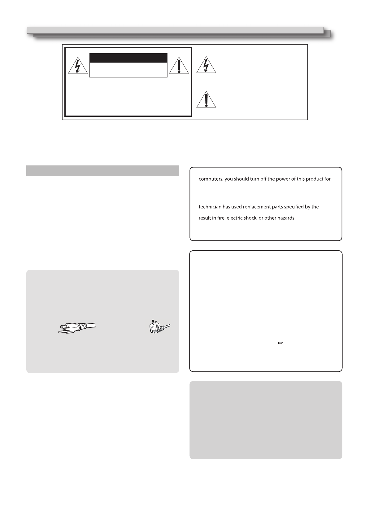
CAUTION:
To reduce the risk of electric shock. Do
not remove cover (or back). No user
serviceable parts inside. Refer servicing
to qualified service personnel.
RISK OF ELECTRICAL SHOCK
DO NOT OPEN
Thelightning flash with arrowhead
symbol, within an equilateral triangle is
intended to alert the user to the presence
of uninsulated “dangerous voltage”
within the product’s enclosure that may
be of sufficient magnitude to constitute a
risk of electric shock to persons.
The exclamation point within an
equilateral triangle is intended to alert
the user to the presence of important
operating and maintenance (servicing)
instructions in the literature
accompanying the appliance.
CAUTION
The power supply voltage rating of this product is AC 120 V(For U.S.A. and
Canada) and AC 220 -240 V(For Europe and Asia).
The power cord attached conforms to the following power supply voltage
and countries. Use only the power cord designated to ensure safety and
EMC regulations of each country.
Not all types of power cords are supplied to this product.
For U.S.A. and Canada: AC 120V For Europe and Asia: AC 220-240V
This plug will fit only into a grounded power outlet. If you are unable to
insert the plug into the outlet, contact your electrician to install the proper
outlet. Do not defeat the safety purpose of the grounded plug.
This product should be operated only with the type of power source
indicated on the label. If you are not sure of the type of power supply of
your home, consult your product dealer or local electric power company.
POWER CONNECTION