Project EV ATESS EVA-11S User manual

ATESS EVA-11/22/44S
3-phase AC charger
Quick installation guide
Lakes Court, Lancaster Business Park, Newborough Road,Needwood,
Burton Upon Trent, Staffordshire DE13 9PD
www projectev co uk. . .
Project EV

This user manual is copyrighted by Growatt Power
Technology. (hereinafter referred to as “Growatt New
Energy”). No company or individual may extract or copy
part or all of this user manual without the written
permission of Growatt Power Technology .Content must
not be transmitted in any form, including materials and
publications.
All rights reserved.
Growatt Power Technology has the final right to
interpret this user manual. The information in this
manual is subject to change without notice.
Disclaimer

Menu
I. Product description
II. Packaging list
III. Installation and wiring
IV. Parameter setting
4.1 Set computer’s IP
4.2 Configure parameters
4.3 DIP configuration and definition
V. Operation instruction
5.1Charging mode and Operation
5.2 LCD interface introduction
5.3 Fault code
VI.Introduction of power management and off-peak
charging
6.1 Power management
6.2 Off-peak charging
VII.Home WiFi connection
VIII.Change server URL
IX.How to use power modulation
X. How to update FW
XI. How to issue RFID card
XII.Specification
XIII.Annex
8.1 Electrical diagram
8.2 Contact
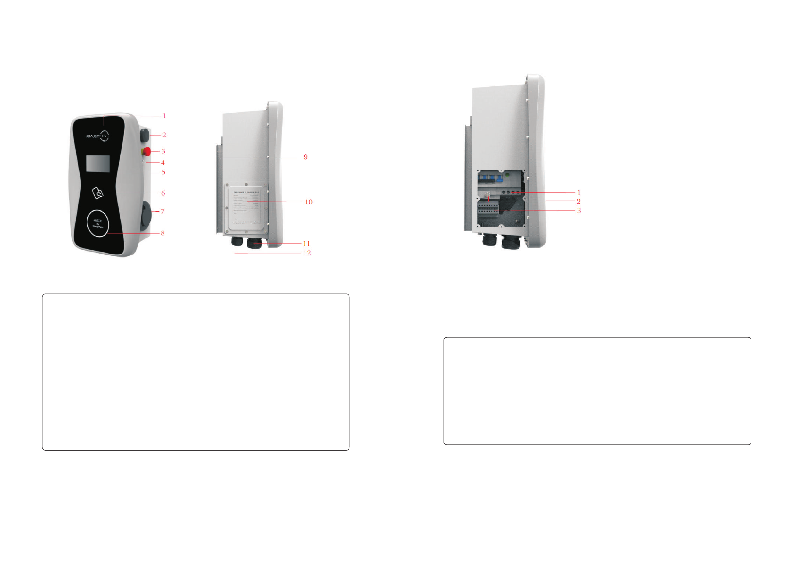
I.Product description
1.LOGO and logo backlight;
2.WIFI/4G Antenna;
3.Emergency stop button;
4.Forced On/Off button;
5.LCD display;
6. RFID reader;
7.Socket outlet (plug holder for cabled version)
8.Status indictor;
9.Mounting bracket;
10.Side window and nameplate;
11.Waterproof cable gland for AC input
12.Waterproof cable gland for c
ommunication wires;
Wiring definition in the side window
If there is terminal definition on the rear side of the side window cover, please use
the definition on the cover for CT and meter wiring.
If not, please use the following:
1.AC input terminals. Terminal definition is (①N;②L1;③L2;③L3).
2.PE terminal
3.Terminal block for CT/meter wiring. The terminal definition is:
(①Ia+;②Ia-;③;④Ib-;⑤Ic+;⑥Ic-;⑦A;⑧B )
③ ④ ⑤ ⑥ is for CT connection.
Ib+
①②
⑦ and ⑧ is RS485 terminal for meter connection;
II.Packaging list
No. Name Qty Remark
1
2
3
4
1
1
1
1
Charger
User manual
Quality certificate
Mounting bracket
5
6
7
Cable hook
ST6.3X40
Stainless steel hex-head
self-drilling screws
12X46
Plastic expansion plugs
1
4-7
4-7
For cabled version
4 for socket version, 7 for cabled
version(3 of the 7 screws is for
cable hook fixing)
4 for socket version, 7 for cabled
version(3 of the 7 plugs is for
cable hook fixing)
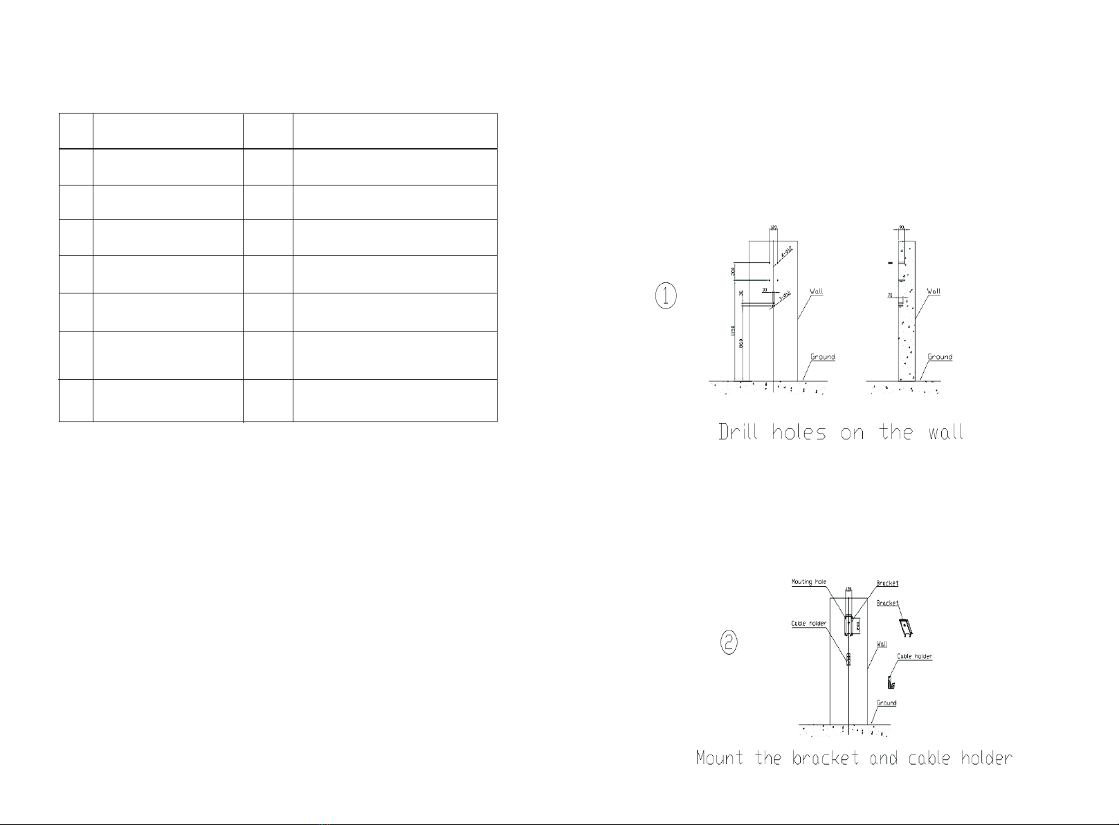
III.Installation and wiring
1.First determine the installation height of the charger. Then drill 4 holes on the wall
according to the distance and size marked below. If the charger is a cabled version,
drill another 3 holes below the charger for installation of cable hook. Take out the
hex head self-drilling screws and plastic expansion plugs. Hit the plastic expansion
plugs into the holes using hammer. Place the screws properly for later use.
2.Unscrew the 2 screws fixing the mounting bracket and place the screws properly
for later use. Place the mounting bracket onto the wall, align with the mounting
holes and fasten it with the hex-head screws. For cabled version charger, install the
cable hook using same method.

4.After the installation is done, then you can do the wiring work. Open the front lid
and the side window. Connect the AC input cables to the cable terminals through the
AC input waterproof cable gland. The size requirement of the AC input cables is:
4-6mm² for 22kW charger and 10-12mm2 for 44kW charger (Use insulated crimp
wire ferrules). The PE for 22kW and 44kW charger should be at least 4mm² and
10mm2 respectively (Use insulated crimp ring terminal).
Connect the other wires(e.g. CT wires, meter wires or LAN cable) to the
corresponding terminals through the communication waterproof cable gland. Fasten
the cable glands and turn on the RCBO inside the side window. Fix the front lid back
on the charger, then the wiring is done. Turn on the upstream breaker, and connect
the charger to computer for parameter setting. The charger will be ready for use
after the parameter setting.
3.Place the charger onto the mounting bracket and fix it with the 2 screws at the
bottom of the charger. Then installation is done.
If the charger is supplied by a PME system, a specific earthing rod might be
needed for the installation to comply with BS7671 regulation.
Notice
1.Only professional person can do the installation and wiring. L1, L2, L3 and N of the
AC input must not be connected incorrectly!
2.The Charger must be connected to the earth securely and reliably.
3.No live work! Please turn off the RCBO and the upstream breaker before any
maintenance work.
4.Do not disassemble the Charger except for professional persons.
After the installation and wiring is done, connect the Charger to a computer and
configure parameters via the web browser of the computer, then the Charger can be
ready for use.
IV.Parameter setting
4.1 Set computer’s IP
The Charger’s default IP address is 192.168.1.5. To access the parameter setting
interface, you’ll need to first set the computer’s IP to 192.168.1.x(x can be any value
between 1 and 255 except for 5, e.g. 192.168.1.10).
To set a static IP on your Windows computer:
1.Click Start Menu > Control Panel > Network and Sharing Center. (For Windows
8 and higher, search for and open Control Panel and select Network and Internet).
2.Click Change adapter settings.

Connect the charger to a computer via a network cable. Open the web browser and
type in http://192.168.1.5:8080/ in the address field and click enter, then the
parameter setting page of the charger will open up.
Parameter setting can only be done via web browser on a computer. It is suggested to
use IE or Firefox, other browser might have compatibility problem.
4.2 Configure parameters
3.Right-click on and click on .Local Area Connection Properties
4.Select and click on .Internet Protocol Version 4 (TCP/IPv4) Properties
5.Select "Use the following IP address" and enter the IP address, Subnet Mask,
Default Gateway. Click and close the Local Area Connection properties window.OK
Overview of Parameter setting page

(3)Charger IP. The default IP is 192.168.1.5. It is not suggested to change the
default IP. If you have changed the default IP and forgot the new IP, you can reset the
charger to factory setting by long press the reset button(the reset button on control
board, not the red emergency stop button) until the charger reboot. Then you can
use the default 192.168.1.5 for access.
(1)Firmware version of the Charger. This item cannot be modified here on the
setting page.
Overview of Parameter setting page
enlarged view of parameter setting page_2
Explanation of parameters:
Fig.1
(2)Charger ID, this is the unique identification of the Charger. If the charger is to
be connected to Growatt back-office server, this ID must be set as the serial number
on the nameplate of the Charger. Otherwise the Charger cannot be registered on the
server.
Fig.2
Please note: After restoring the charger to factory setting, you’ll need to reset
the charger ID(same as serial number, can be found on the nameplate sticker)
and server url, otherwise the charger won’t be connected to the back-office
server.
Fig.3
enlarged view of parameter setting page_1
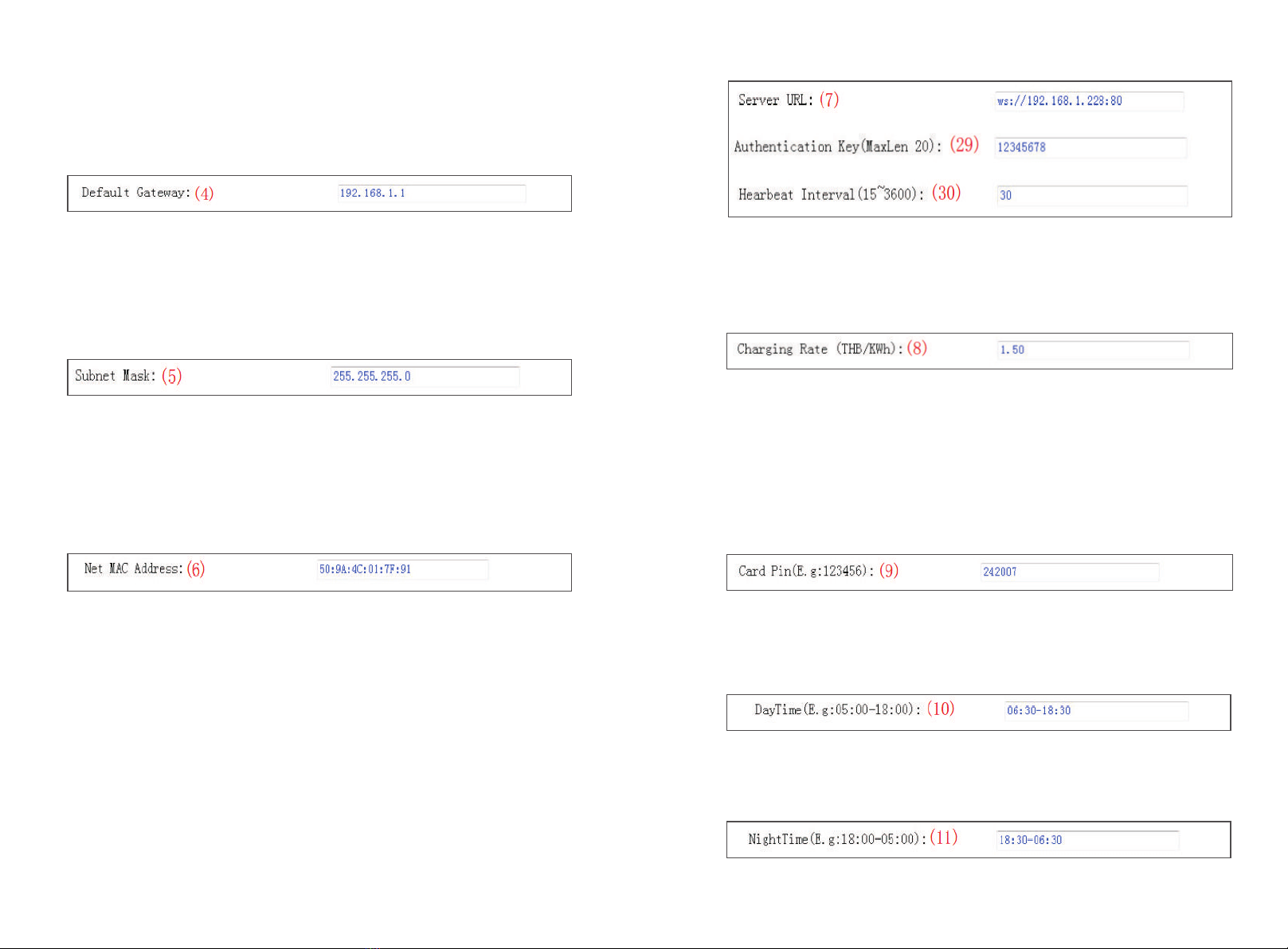
(4)Charger gateway. The default value is 192.168.1.1. It is not suggested to
change. If the gateway has been reset to other value and you have forgotten the new
value, you can restore the charger to factory setting by long press the reset button.
Fig.4
(5)Charger Subnet mask. The default value is 255.255.255.0. It is not suggested
to change. If the subnet mask has been reset to other value and you have forgotten
the new value, you can restore the charger to factory setting by long press the reset
button.
Fig.5
(6)MAC address. This is the MAC address used for LAN cable connection. If the
charger is connected to Growatt back-office server via LAN cable and the router has
MAC access control, then you can put this MAC in the router to allow the charger to
access server
Fig.6
(7)Server URL is to set the domain name or IP address of the back office server to
be connected.
The domain name of Growatt server is “ws://charge.growatt.com:80/ocpp/ws”;
IP address is “ws://47.254.157.66:80/ocpp/ws”.
Authentication Key and Heartbeat Interval is used for testing and no need to reset.
Fig.7
(8)Charging fee per unit of electricity.
Fig.8
(9)PIN of the charger, used to verify the PIN of user card. To use a RFID card with
the charger, their PIN must be consistent. If the user card has a different PIN, then it
cannot be used on this charger. The default PIN setting of the charger is 242007.
Fig.9
(10)Peak time period. Set the time period of peak tariff.
Fig.10
(11)Off-peak time period. Set the time period of off-peak tariff.
Fig.11

(12)Time of the charger. Set according to the local time.
After the charger is connected to back-office server, the time
will be synchronized with the server’s time. If the charger has
no server connection, then you’ll have to reset the time every
time you turn off and back on the charger.
Fig.12
(13)Language of LCD screen.
Fig.13
(14)Charger DNS setting, this only needs setting when the charger is to connect
to server via LAN cable.
Fig.14
(15)Set the max output of the charger.
(16)Charging mode setting. 1: APP/RFID mode; 2: RFID mode; 3: Plug&Charge
mode.
Fig.15
Fig.16
(17)(18)WiFi SSID(wireless network name) and WiFi Key(WiFi password) is used
for WiFi connection.
Fig.17
(19)(20)Set peak tariff and off-peak tariff.
Fig.18
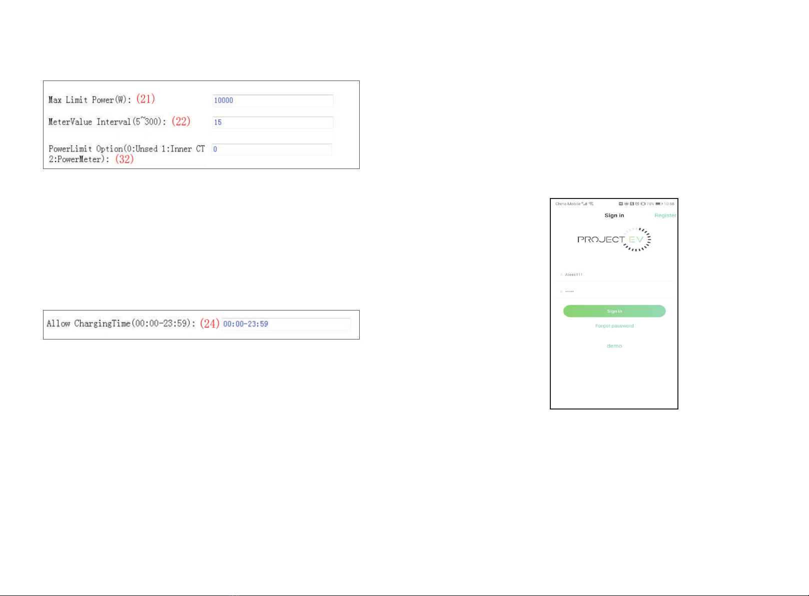
(21) (32)(22) Max power import to the property, Power sampling device
selection, meter value collection interval. These 3 parameters are used for power
management setting.
Fig.19

(23) Over temperature protection value, not suggested to change.
(24) Charging-allowed time. Charging can only start within this time period. This
is used for off-peak charging setting.
If you want to charge out of this period, just press the forced on/off button at the
side of the charger.
Fig.20
Fig.21
(25) DC residual current sampling value calibration. Enter 0 and press “Set and
Reboot” to calibrate the DC RCD ring.
Fig.22
(26) (34) Bluetooth setting. Only needs setting when the charger is equipped with
Bluetooth.
Fig.23
(27)(28) (35) 4G connection setting.
Fig.24
(31)This is for communication testing, no need to reset.
Fig.25
(33)DC residual current real-time detection value.
Fig.26
(36) Press this button for the parameter change to take effect.
Fig.27
(37)This is used to upgrade firmware.
Fig.28
V.Operation instruction
and LCD description
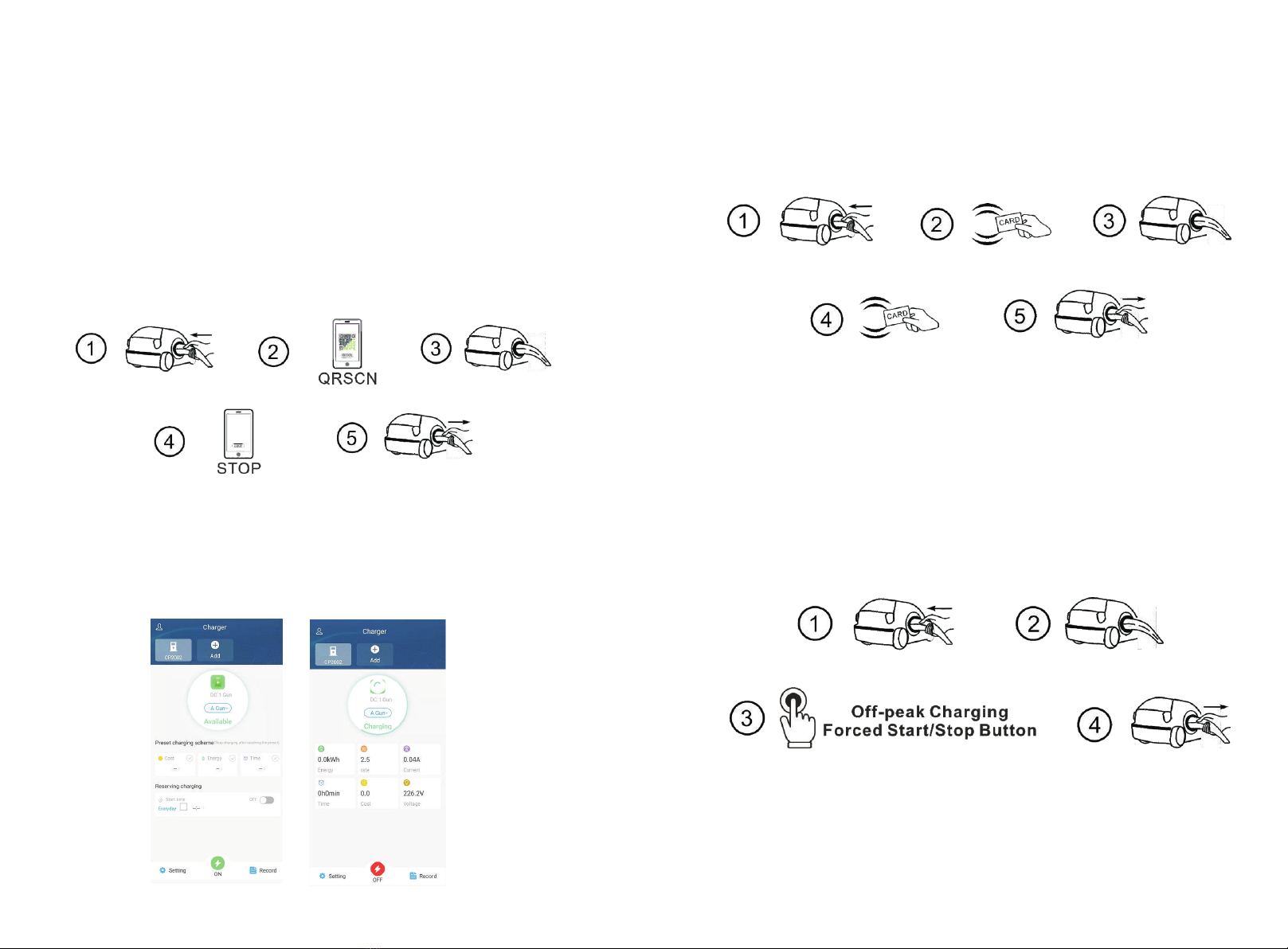
5.1 Charging mode and Operation
APP/RFID mode:
Initiate or cease charging by scanning QR code using APP or by swiping RFID card.
You can also use APP for reservation and payment provided that the back-office
server supports such functions.
APP/RFID mode operation process flow
If you are using the ProjectEV APP, Charging can be started/stopped by pressing the
ON/OFF button on the APP.
RFID mode:
Charging can only be initiated or ceased by swiping RFID card.
RFID mode operation process flow
Plug&Charge:
Charging will start automatically after EV plugged in. If you want to stop the
charging, just press the forced on/off button on the side of the charger.
Plug&Charge mode operation process flow

5.2 LCD interface introduction
Interface of standby status.
Charging mode is displayed at
the bottom centre of the screen.
Interface of user card information
Displayed for user to check card ID
and balance when swiping RFID
card while EV is not connected
Interface of charging status.
Displayed when the charging is
being carried out. There is charging
time, consumed electricity,
charging cost on it, as well as
real-time charging voltage and
charging current.
Interface of charging complete.
Displayed when the EV stops
charging, or forced on/off button
is pressed on charger side.
Interface of billing.
After scanning QR code or swiping
RFID card for billing, this interface
will open up to display user
ID/charging time/cost/balance,
etc.This interface will also come
out when you stop charging on
the Project EV APP or when you
press the forced on/off button
or unplug the gun at
Plug&Charge mode.
Interface of fault status.
Displayed with fault code and fault
description when fault occurs.
Interface of reserved status.
If the back-office server and APP
support reservation function and
the charger is reserved, this
interface will come out showing
user ID and remaining time to
reserved time.

No. Fault code Definition description
1
2
3
4
100
101
102
5.3Fault code
103
5
6
7
8
104
106
105
107
Emergency stop pressed,
or emergency stop is broken
L3 phase overvoltage
L3 phase undervoltage
L2 phase overvoltage
L1 phase overvoltage
L1 phase undervoltage
Three phase undervoltage
L2 phase undervoltage
108
109
110
111
1000
9
10
11
12
13
Over current
Over temperature
RCD Leakage Protection
485 error
Other errors
VI.Introduction of power management
and off-peak charging
6.1 Power management
The working principle of power management is as below,
Assume the max current can be supplied to the property is 40A, then the max power
is 40Ax230V = 9.2kW. So you can set the max power import to 9.2kW.
If CT is used to detect power import, then select CT as the power sampling device in
the parameter setting page. The charger will adjust charging power according to the
real-time power import and max power import.
When real-time import exceeds 90% of the preset max import value, the charger will
decrease charging power at a rate of 2A/sec until the real-time value drops between
80%-90% of the max value.
.
When real-time import drops below 80% of the max value, the charger will increase
charging power at 2A/sec until the real-time import falls between 80%-90% of the
max import value
Block diagram of power management
① Connect computer to the charger and enter the parameter setting page.
②
③Connect the CT wires or meter wires properly.
Set the max allowable power import and select power-sampling device. If meter is
used for power sampling, sampling interval also needs to be set.
6.2 Off-peak charging
① Connect computer to the charger and enter the parameter setting page.
② Set the allow charging time according to the local off-peak time period. Charging
is only allowed in this period unless the forced On/Off button is pressed. In peak time
period, plug the car to the charger, charging will wait until the off-peak time arrives.
VII.Home WiFi connection
If the ATESS EV charger you bought is WiFi version, then you can connect it to the
home WiFi and then monitor and control the charging on the Project EV APP.
There are 2 ways to set up the home WiFi connection, do it using a laptop connected
to the charger by LAN cable, or set up the connection directly on the APP.
In this instruction, we will show how to do it using the APP. Procedure is as below,
1. Open the “Project EV” APP, register an account and login with this account;
2. After login, click the “Add device” to add your EV charger to your account;

3. Enter the charger’s serial number, which can be found on the left hand side of the
charger, and click “Yes”;
4. Click the WiFi icon on the top right corner of the APP to connect your mobile to
the hotspot of the EV charger;
5. Turn on the breaker of the EV charger to power it up, then click “Go to the WLAN
page to set up” to connect the mobile phone to the hotspot generated by the
charger. The name of the hotspot is the charger’s serial number, the password is
12345678.

Please note: Every time when the charger is powered up, it will emit WiFi for 90sec,
you can connect the APP to this hotspot and set up charger parameters and home
WiFi connection during the 90sec. After 90sec, the charger will try to connect to the
home WiFi with the SSID and password information just filled in, the attempt will last
60sec. If the charger fails to connect to the home WiFi within the 60sec, it will emit
WiFi for another 90sec again for you to redo the setup.
6. When the charger’s hotspot is connected, your mobile might prompt you that this
is an non-Internet-accessible WiFi, Please select to connect it anyway. Then press the
arrow icon on the top left corner of the screen;
7. Click the “Next” button. Please check and make sure the mobile is connected to
the hotspot of the charger;
8. The APP will then obtain the charger’s parameters and enter the setting page;

9. Enter the name and the password of the home WiFi;
1 0 . S c r o l l d o w n t o s e t t h e s e r v e r a d d r e s s , w h i c h s h o u l d b e
“ws://charge.growatt.com:80/ocpp/ws” or “ws://47.254.157.66:80/ocpp/ws”.
Then click “Yes”;
11. Then click the arrow icon to back to the home screen, the charger will restart
when you exit the setting;
12. Wait for around 3 min, the charger will be online and ready for use.
VIII.Change server URL
The server URL is the address of the back-office server to which the charger will
connect to, it will be preset in factory before shipped out. In very few occasions, you
m i gh t f i n d t h a t t h e s e rv e r U R L i s i n c o r r e c t ( t he c o rr e ct s e t t i n g i s
“ws://charge.growatt.com:80/ocpp/ws”). If this happens, you’ll need to change it
using a laptop. The procedure is as below,
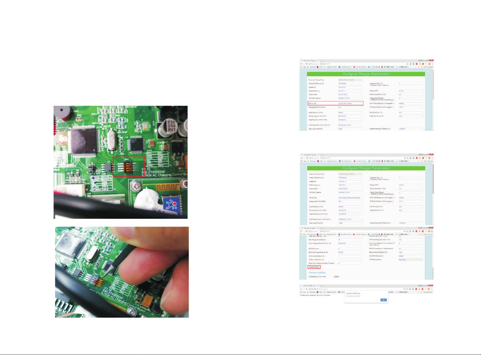
1. Open the front cover of the charger, set the all 4 bits of the DIP switch to ON
position(you need to first remove the film on the DIP switch using a tweezers);
2. Power up the charger, connect it to a laptop whose IP is in the same network
segment with the charger(should be192.168.1.x, while x is any value between 1 and
255 except 5). Then open the web browser to access the parameter setting page of
the charger;
3 . C ha ng e t he se rv er U R L t o t h e c or re ct se tt in g, w hi ch s h ou ld b e
“ws://charge.growatt.com:80/ocpp/ws”;

5. After the charger is restarted, enter the parameter setting page again to check if
you have changed it successfully. After that, please set the 4 bits of the DIP switch
back to OFF position.
IX.How to use power modulation
I. How does intelligent power adjustment work?
Intelligent power adjustment needs a power-sampling device on the incoming mains
supply cables, which could be a power meter or a current transducer and normally
located in the meter box.
Charger will adjust the charging power according to the pre-set power limit and the
real-time power consumption to ensure the total power import not exceed the
supplying capacity and not trip the main breaker.
Block diagram of power adjustment
II. Intelligent power adjustment setting
1.Connect the charger to a computer whose IP address should be set within the
192.168.1.x segment(x can be an y value be t w e en 1 an d 25 5 exce p t 5) ,
Enter the charger’s IP address of “http://192.168.1.5:8080” in the web browser and click
“Enter” to get into the parametersetting page of the charger.
This manual suits for next models
2
Table of contents
Other Project EV Batteries Charger manuals

Project EV
Project EV EVA-07D-SE-RFID User manual

Project EV
Project EV Dual Wall Pro Earth User manual

Project EV
Project EV EVA-07S-SE-C User manual

Project EV
Project EV EVA-22S-SE-RFID User manual

Project EV
Project EV EVA-07S User manual

Project EV
Project EV EVA-07D-SE-W User manual

Project EV
Project EV APEX-7.3 User manual

Project EV
Project EV EVA-07S-S User manual


