mdp 12V-10A User manual

OPERATING AND
USERS MANUAL
UK
www.mdpelectronics.fr
12V-10A
12V-15A
12V-25A
12V-40A
24V-20A
BATTERY CHARGER
FIRST

WARNING
BEFORE OPERATION
THIS MANUAL CONTAINS VITAL AND ESSEN-
TIAL INFORMATION. IN ORDER TO AVOID
ELECTRICAL SHOCKS OR OTHER DAMAGE,
THE OWNER SHOULD READ AND UNDERS-
TAND THIS IMPORTANT DOCUMENT BEFORE
OPERATING THE CHARGER.
Contact mdp electronics if you do not unders-
tand a statement.
This device is not intended for use by persons (in-
cluding children) with physical, sensory or men-
tal disability, or by persons lacking experience
or knowledge, unless they have received from a
person in charge of their safety adequate super-
vision or preliminary instructions on how to use the
device.
Before Installation.
4In order to avoid overcharging or irreversible
damage to the materials, please follow closely
all recommendations cited below. Do not install
this system near inammable materials. An owner
should seek guidance from an authorized DOL-
PHIN dealer or the factory.
4Do not install this device near a heat source.
4It should not be installed in an airtight or badly
ventilated area.
4All ventilation ducts must be unobstructed.
4Leave at least 10 cms / three inches clearance
around the device for proper ventilation.
4Mount in a vertical position, to create natural
ventilation for the charger. Note that the wiring
connections are at the bottom of the charger.
4All electrical connections to and from the
charger must remain accessible at all times.
FIRST-rev 01

4This system should not be exposed to water or
dust.
4It is strictly forbidden to tamper with the system
casing in any way.
4This device is not a toy and must be kept out of
the reach of children.
Connecting the Device.
In order to avoid all risk of electric shock or irrever-
sible damage to the device, please follow very
carefully the following recommendations
4This device is set to be connected to a mono-
phase network 230V 50Hz or 115V 60Hz (except
10A & 15A)
4The installation to which the device is connec-
ted must comply with the standards currently en-
forced in the country of use.
4In order to protect the occupants, the input
point must be attached to a differential circuit
breaker. Please refer to the specic characteris-
tics of the circuit breaker.
4For security reasons, the system’s PE terminal
must strictly be connected to the installation’s
Earth (green/yellow wire in the cable section).
Please consult the wiring diagram.
4To prevent overheating, ensure the correct
connection and size of cables.
4The input cable must not exceed 3 meters (10
feet) and the output cable 1.5 meters (5 feet).
4All cable connections and connectors must
be maintained in good condition. Once the
connection of the AC cable has been comple-
ted it is imperative to t the Winsta Wago snap
on security cover. See “Assembling the Shore
Power Connector”
FIRST-rev 01
UK

Start up precautions.
In order to avoid all risk of electric shock or irrever-
sible damage to the device, please follow very
carefully the following recommendations.
4Do not dismantle the device. The housing (pro-
tection against re) must be correctly mounted.
4This device complies with enforced standards;
regarding emitted interference, protection
against disturbances of external origins (refer to
the paragraph on EMC – Technical Specica-
tions.)
4When in use, avoid submitting the device to le-
vels of interference, in particular electromagnetic
and conducted, superior to those legally permit-
ted (for example, the devise installed too close
to an emitter) as this may cause irreversible da-
mage.
4This device emits interference (electromagnetic
and conducted) which complies with legal stan-
dards. Ensure that materials used are compatible
i.e. susceptible, with this device in order to avoid
irreversible damage.
Series number.
This reference is found on a grey sticker on the
side of the charger. It is made up of: 2 digits in-
dicating the manufacturing year; 09 for 2009, a
letter representing the month; C for March, and
a 4 or 5 digit number indicating the production
number.
Rev XX refers to the number of modications /
evolution of the product since its initial launch.
WARNING
FIRST-rev 01

NB: Choosing the charging curve.
It is extremely important to choose the correct
charging curve, one which is appropriate for the
battery’s technology. An incorrect choice could
cause irreversible damage.
4This is particularly true for charging curves where
the charging voltage is higher than the manufac-
turers’ recommended voltage levels.
4There is a high risk of overheating and emission
of noxious gases
4Charging curve 4 is compatible with LiFeSo4
batteries that have a BMS (battery management
system) installed.
4It is essential to consult the battery manufactu-
rer’s recommendations.
Maintenance precautions.
4This device cannot be dismantled and thus the
PC board is inaccessible. It is strictly forbidden
to dismantle the housing for any reason. Electric
shock possible.
4In order to prevent risk of electric shocks during
maintenance, please follow closely all recom-
mendations below before any maintenance be-
gins.
4Any operation carried out to this effect must be
carried out by an authorized electrician.
In the event of damaged wires or cables, these
must be replaced by an authorized electrician.
The end user must not attempt to change them.
4The mains and battery connections must be dis-
connected before any work is carried out in order
to avoid transfer of energy
4Fuses must be replaced by fuses that have the
same characteristics and performance levels.
FIRST-rev 01
UK

Lead open
battery Battery type: Lead open
V.boost = 14.2V
V.oat = 13.2V = 28,4V
= 26,4V
Gel, AGM, Spiral
battery Battery type: GEL, AGM, Spiral
V.boost = 14,2V
V.oat = 13,7V = 28,4
= 27,4
Lead calcium
battery Battery type: Lead Calcium
V.boost = 14,8V
V.oat = 13,7V = 29,6
= 27,4
Power Supply
or LiFeSo4 with
integrated BMS
battery
Battery type: Power supply or LiFeSo4+BMS
V.boost = 14,2V
V.oat = 14,2V = 28,4
= 28,4
Weekly Equalization automatic
Voltage Allowance +/- 2%
Residual wave < 1% pp (BW < 20 MHz)
Current 10A 15A 25A 40A 20A
Fuse F15A
32V
Automotive
F20A
32V
Automotive
2xF15A
32V
Automotive
2xF25A
32V
Automotive
2xF15A
32V
Automotive
Protections
Against output overload, output short circuit,
excessive internal temperature, excessive
battery temperature, output overvoltage,
battery reverse polarity (fuse)
General
Display Tricoloured LED
Night mode
(Diagram B) / / Button
Operating temp -10°C to +50°C / +14°F to +122°F
Storage temp -20°C to +70°C / -4°F to +158°F
Humidity 10% to 90% (without condensation)
Ventilation Natural Forced fan cooling
EMC EN61000-6-3 & EN61000-6-1
Security EN60335-2-29 (2002)
Housing White aluminium – wall mounted
Mounting 2 x 4mm screws
Dimensions (mm) 238(h)x120.5(w)x95.6(d) 354(h)x120.5(w)x 95.6(d)
Weight 1.3 kg / 2.87lbs 1.9 kg / 4.2lbs
Ac Connection 3 points, 20A 230V, 4mm_max
Ref : 770.813/G11-000 (WINSTA - WAGO)
Battery Connection 4 points, 40A 630V, 10mm_max
Ref : PC 6-16/4-G1F-10,16 (PHOENIX CONTACT)
12V 10A 12V 15A 12V 25A 12V 40A 24V 20A
WARNING
FIRST-rev 01
Charge selector
Diagram A :

Lead open
battery Battery type: Lead open
V.boost = 14.2V
V.oat = 13.2V = 28,4V
= 26,4V
Gel, AGM, Spiral
battery Battery type: GEL, AGM, Spiral
V.boost = 14,2V
V.oat = 13,7V = 28,4
= 27,4
Lead calcium
battery Battery type: Lead Calcium
V.boost = 14,8V
V.oat = 13,7V = 29,6
= 27,4
Power Supply
or LiFeSo4 with
integrated BMS
battery
Battery type: Power supply or LiFeSo4+BMS
V.boost = 14,2V
V.oat = 14,2V = 28,4
= 28,4
Weekly Equalization automatic
Voltage Allowance +/- 2%
Residual wave < 1% pp (BW < 20 MHz)
Current 10A 15A 25A 40A 20A
Fuse F15A
32V
Automotive
F20A
32V
Automotive
2xF15A
32V
Automotive
2xF25A
32V
Automotive
2xF15A
32V
Automotive
Protections
Against output overload, output short circuit,
excessive internal temperature, excessive
battery temperature, output overvoltage,
battery reverse polarity (fuse)
General
Display Tricoloured LED
Night mode
(Diagram B) / / Button
Operating temp -10°C to +50°C / +14°F to +122°F
Storage temp -20°C to +70°C / -4°F to +158°F
Humidity 10% to 90% (without condensation)
Ventilation Natural Forced fan cooling
EMC EN61000-6-3 & EN61000-6-1
Security EN60335-2-29 (2002)
Housing White aluminium – wall mounted
Mounting 2 x 4mm screws
Dimensions (mm) 238(h)x120.5(w)x95.6(d) 354(h)x120.5(w)x 95.6(d)
Weight 1.3 kg / 2.87lbs 1.9 kg / 4.2lbs
Ac Connection 3 points, 20A 230V, 4mm_max
Ref : 770.813/G11-000 (WINSTA - WAGO)
Battery Connection 4 points, 40A 630V, 10mm_max
Ref : PC 6-16/4-G1F-10,16 (PHOENIX CONTACT)
12V 10A 12V 15A 12V 25A 12V 40A 24V 20A
TECHNICAL SPECIFICATIONS
FIRST-rev 01
UK
Button – Night Mode
Diagram B :
Input
Tension 230V +/- 15%
115V please
consult us
115V - 230V
(+/- 15%)
Frequency 50Hz - 60Hz (+/- 10%)
Cos phi 0.6 typ 0.9 typ
Efciency 80% typ
Mains consumption 1.3A 1.9A 4A/2A 7A/3.5A
Fusible
T2A
250V
5x20mm
T3, 15A
220V
5x20mm
T6A
250V
5x20mm
T10A
250V
5x20mm
Output
Nb of outputs 3 isolated outputs
Nb charginig curves 4 possible charging curves.
Selection by external dip-switch
Curves types IUUo & automatic weekly equalization
Charging
proles
(Diagram A)
12V 10A 12V 15A 12V 25A 12V 40A 24V 20A

OPERATING INSTRUCTIONS
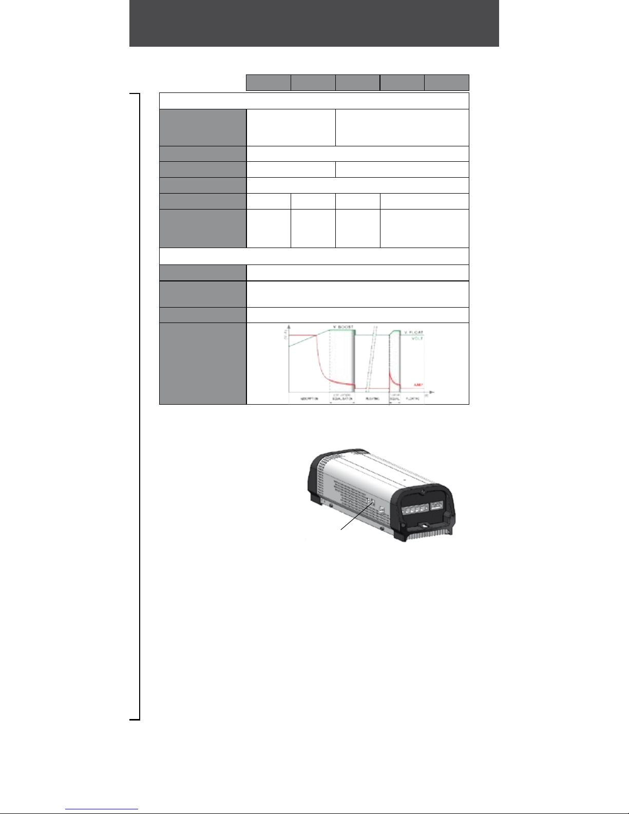
MODE
Absorption
Equalisation
End of
Equalisation
Floating
Internal
Temperature
fault
Output
voltage fault
Battery
fuse fault
“Night” Mode
12V-25A
12V-40A
24V-20A
LED
Steady
yellow
(1)
Yellow
blinking
(2)
Green
blinking
(3)
Green (4)
Red
xed
(5)
Red
blinking
(6)
Red
Flashing
(7)
-
STATUS
The batteries are charging. Time
required to complete Absorption
mode varies depending on the
initial status of the batteries, but is
limited to 6 hours.
The batteries are coming to the end of
the charging cycle. Time required to
complete Equalization mode, depen-
dingontheinitialstatus ofthebatteries,
varies from 30 minutes to 4 hours.
The batteries are almost charged.
Floating mode will begin in less
than 30 minutes.
The batteries are completely charged.
The charger is on Standby for a
period of between 30 seconds
and 10 minutes. Once the fault has
been solved, the device will start
up again automatically.
4If this problem arises, please
check the external temperature
as well as the internal fan and the
space around the charger.
The charger is on Standby for a pe-
riod of 30 seconds. Once the fault
has been solved, the device will
start up again automatically.
4In reality, the PC Board has pro-
bably failed and the damage is
irreversible.
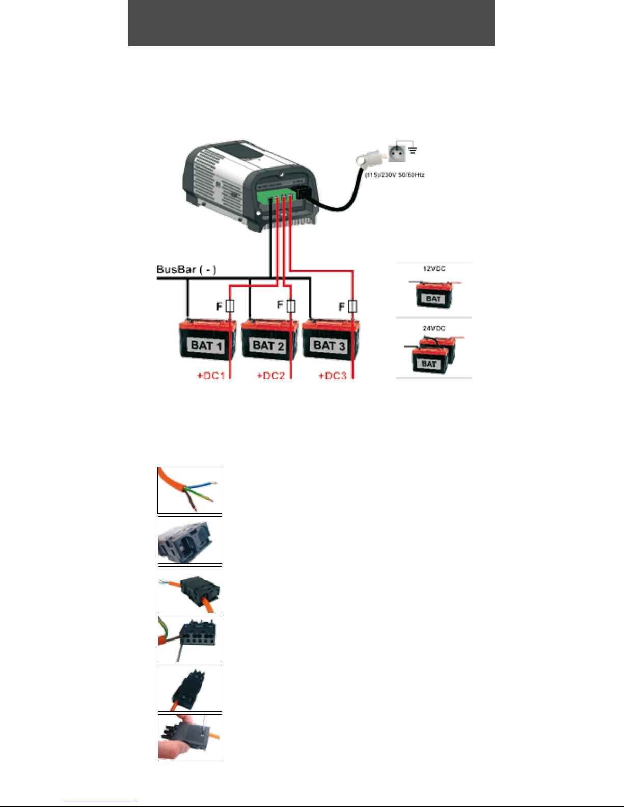
The fuse should be replaced.
4Please check all connections as
well as the battery’s polarity and
status
This mode allows the charger to
work without noise (from the fan).
In this case, charging levels adapt.
To activate this mode, press the
button for about 2 seconds. To
deactivate, a simple press of the
button or the mode deactivates
automatically after 10 hours.
FIRST-rev 01
(1)
(2)
(3)
(4)
(5)
(6)
(7)

RACCORDEMENTS
Mounting
(4mm screws)
Bottom
(Connector side) Top
Program
selector
Night mode selector button
Battery Fuse
Recommended
cable size
12V10A : 2.5 mm2 /12 AWG
12V15A : 2.5 mm2 / 12 AWG
12V25A : 4.0mm2 / 10 AWG
12V40A : 6.0 mm2 / 8 AWG
Lg cables : 1.5 m / 4.9 feet max
Recommended
cable size
12V10A : 3 x 0.75 mm2 / 18 AWG
12V15A : 3 x 0.75 mm2 / 18 AWG
12V25A : 3 x 1.5 mm2 / 14 AWG
12V40A : 3 x 1.5 mm2 / 14 AWG
Lg cables : 3 m / 9.8 feet max
12V-25A
12V-40A
24V-20A
12V-10A
12V-15A
Program
selector
Battery Fuse
FIRST-rev 01
UK
Cable type: according to local regulations

CONNECTION
FIRST-rev 01
Wiring diagram
Assembling the shore
power connector
7STEP 1:
Remove approx 2 cm of the outer sheath
Remove approx 8 mm of the inner wires’ sheaths
Tinplate the bare copper ends
7STEP 2:
Remove the security cap using an utility knife
7STEP 3:
Pull the conductor through the pre latched strain
relief housing
7STEP 4:
Open the clamp with a screwdriver and insert the rst
cable up to the stop. Repeat this step for all three cables.
7STEP 5:
Latch the connector on to the strain relief housing.
7STEP 6:
Snap together the upper and lower parts of the strain
relief housing and tighten it using the screw.
Dispatching

UK
DIMENSIONS
Dimensions 12V-10A / 12V-15A.
Dimensions 12V-25A / 12V-40A / 24V-20A
x2 ø5mm
20mm
[0.79inch]
95,6mm
[3.76inch]
120mm
[4.74inch]
238mm [9.37inch]
210mm [8.27inch]
352,5mm [13.88inch]
326mm [12.83inch]
120mm
[4.74inch]
95,6mm
[3.76inch]
20mm
[0.79inch]
x2 ø5mm
FIRST-rev 01

WARRANTY
IN ORDER TO PREVENT ALL RISKS ARISING DUE
TO THE INCORRECT USE OF THIS DEVICE, PLEASE
CAREFULLY READ THE LIST OF POSSIBLE SITUA-
TIONS OR FAULTS THAT ARE NOT COVERED BY THE
WARRANTY.
4If the mechanical components of the device
are not protected by the casing and fall, irreversi-
ble damage of the ventilation system and certain
electrical components may result.
4Modications made to the casing (and in parti-
cular if holes are bored), may result in the deposit
of metallic shavings or lings onto the electronic
card and consequently may cause the malfunc-
tion of or damage to the device.
4Interfering with or modications made to the
PC Board may result in unforeseen operations
and consequently may cause the malfunction of
or damage to the device.
4Use of a non-adapted power supply (as a ge-
neral rule, the input voltage will be too high) may
cause the malfunction of or damage to the de-
vice.
4Over voltage from the mains or a lightening
strike will usually cause irreversible damage to the
PC Board.
4Replacement of battery fuses with fuse types
other than those recommended (same charac-
teristics) may cause the malfunction of or dama-
ge to the device.
4Obvious connection errors will result in the mal-
function of or damage to the device.
4Water gaining access to the interior of the de-
vice may cause the malfunction of or damage to
the device.
FIRST-rev 01

NB: Choosing the charging curve.
It is extremely important to choose the correct
charging curve one which is appropriate for the
battery technology. An incorrect choice could
cause irreversible damage.
4This is particularly true for charging curves where
the charging voltage is higher than the manufac-
turers’ recommended voltage levels.
4There is a high risk of overheating and emission
of noxious gases
4Charging curve 4 is compatible with LiFeSo4
batteries that have a BMS (battery management
system) installed.
4It is essential to consult the battery manufactu-
rer’s recommendations.
Disposal.
This device contains electronic components &
material that must be recycled once the device
is obsolete.
All obsolete electronic devices must be returned
to a local distributor or to a specialized company
for an environmentally friendly disposal.
FIRST-rev 01
WARRANTY UK
CE CONFORMITY
This product conforms to current European
standards and has a CE mark. Please consult us for
the certicate of conformity.

For further information or assistance,
please contact:
mdp electronics
144 route des Vernes
74370 Pringy
FRANCE
Tél : (33) 0 450 272 030
Fax : (33) 0 450 272 774
www.mdpelectronics.fr
This manual suits for next models
4
Table of contents
Popular Batteries Charger manuals by other brands

Lincoln
Lincoln 1870 Installation and maintenance guide

e-Station
e-Station EVR3 user manual

Energenie
Energenie EG-MC-005 user manual

Analytic Systems
Analytic Systems BCD615-48-48 Installation & operation manual

PowerTraveller
PowerTraveller Powergorilla quick start guide

PAG
PAG PAGlink pl16+ instruction manual