STORZ POWER 10354 User manual

INSTALLATION MANUAL
Storz Wall Mount Battery Cabinet | SKU: 10354
19.375” x 12.75” x 37.75” | 72 lbs. | IP65
v1.1 | 2023.4.11 | pg. 1

A I
pg. 2
STORZ WALL MOUNT BATTERY CABINET INSTALLATION MANUAL
+ TABLE OF CONTENTS
IMPORTANT SAFETY WARNINGS
-General
-Storz Wall Mount Battery Cabinet
-Maintenance
-Limitations of Liability
-Important Note
EQUIPMENT NEEDED (NOT INCLUDED IN BOX) FOR
-Storz Wall Mount Battery Cabinet
-Recommended Protective Equipment
PACKING LIST FOR
-Storz Wall Mount Battery Cabinet
-Storz Power Battery
INSTALLATION
-Selecting Mounting Location
-Mounting the Cabinet
-Install Configurations
www.storzpower.com |connect@storzpower.com |833-786-7901 |2961 W. Maple Loop Dr. Suite 300 Lehi, UT 84043

• DO NOT expose Storz Power Battery or Storz Wall Mount Battery Cabinet to flammable or harsh
chemicals or vapors.
• DO NOT paint any part of the Storz Power battery or Storz Wall Mount Battery Cabinet, including any
internal or external components.
• DO NOT connect Storz Power battery or Storz Wall Mount Battery Cabinet with PV solar wiring
directly.
• Any object external from installation instructions is PROHIBITED to be inserted into any part of the
Storz Power battery or Storz Wall Mount Battery Cabinet
• Our company WILL NOT bear any warranty claims for direct or indirect damage caused by violation of
the above items.
IMPORTANT SAFETY WARNINGS
PLEASE READ BEFORE INSTALLING CABINET. Keep this
information for future reference.
STORZ WALL MOUNT BATTERY CABINET
pg. 3
A I
• DO NOT install Storz Wall Mount Battery Cabinet without proper Storz Power Certification. Storz
Power REQUIRES equipment to be installed by a Certified Storz Power Installer. Failing to follow this
requirement will result in voiding the Storz Power product warranty. Storz Power will not honor it’s
product warranty for equipment installed by an individual not Certified with Storz Power.
• DO NOT install Storz Wall Mount Battery Cabinet outside of instructions included in this manual.
• DO NOT attempt to install or use Storz Wall Mount Battery Cabinet if it has been damaged.
• This product contains small items that could be a choking hazard - KEEP THESE ITEMS AWAY FROM
CHILDREN.
• REQUIRED: This product is designed to be installed wall mounted on a flat, vertical and structurally
sound surface with at least a 4” waterway. Make sure that the supporting wall surface will safely
support the weight of the equipment and all attached hardware and components.
• During installation, lay product contents on cardboard or other protective surface to avoid any damage.
Failure to follow any of the instructions or warnings in this document can result in electrical shock,
serious injury, death, or may damage the components and the whole system. Storz Power will not be held
responsible for damage to equipment or personal injury resulting from improper use or installation of
product, lack of common sense and personal injury, or for Storz Power products installed by an installer
not Certified with Storz Power.
STORZ WALL MOUNT BATTERY CABINET INSTALLATION MANUAL
www.storzpower.com |connect@storzpower.com |833-786-7901 |2961 W. Maple Loop Dr. Suite 300 Lehi, UT 84043

LIMITATIONS OF LIABILITY
pg. 4
A I
IMPORTANT NOTE
In no event will Storz Power be liable for any damages, personal harm or injury, whether direct or indirect,
special, punitive, incidental or consequential damages (including, but not limited to, lost profits or revenue,
loss of use, lost business opportunities or loss of goodwill) or for the costs of procuring substitute products,
arising out of or in connection with the use of the product, whether such liability arises from any claim
based upon contract, warranty, tort (including negligence), product liability or otherwise, whether or not
seller has been advised of the possibility of such loss or damage. In no event will seller’s total cumulative
liability, from all causes of action and all theories of liability, exceed the total amounts actually paid to seller
by customer under the order that gives rise to any liability hereunder.
When installing Storz Power Batteries onto the Storz Power Wall Mount Battery Cabinet shelves, the
cabinet must already be wall mounted in place on the wall with proper hardware in place. Placing batteries
inside the cabinet while it is unmounted to the wall may result in damage to the cabinet, shelves, batteries,
or personal injury. Storz Power will not be held responsible for damage, loss of equipment, and/or injury
to installers due to improper construction and installation methods. Storz Power is not held liable for
any installation methods attempted outside of instructions in this manual. Storz Power will not be held
accountable for negligence to diligently read the instructions and warnings contained in this manual before
construction of the Storz Wall Mount Battery Cabinet(s) and installation of the Storz Power Batteries.
Complete Storz Power Battery Installation instructions can be found in the Storz Power ESS Installation
Manual. Instructions in this manual, “Storz Wall Mount Battery Cabinet Installation Manual”, does not
replace in part or in whole, any installation instructions found in the Storz Power ESS Installation Manual.
Storz Power Batteries are only referenced in this manual to help guide through the Storz Power Wall Mount
Battery Cabinet Installation process and are not complete Storz Power Battery installation instructions.
Failure to follow any of the instructions or warnings in this document can result in electrical shock,
serious injury, death, or may damage the components and the whole system. Storz Power will not be held
responsible for damage to equipment or personal injury resulting from improper use or installation of
product, lack of common sense and personal injury, or for Storz Power products installed by an installer
not Certified with Storz Power.
MAINTENANCE
• Check that the product is secure and safe to use at regular intervals (at least every three months).
STORZ WALL MOUNT BATTERY CABINET INSTALLATION MANUAL
www.storzpower.com |connect@storzpower.com |833-786-7901 |2961 W. Maple Loop Dr. Suite 300 Lehi, UT 84043

A I
pg. 5
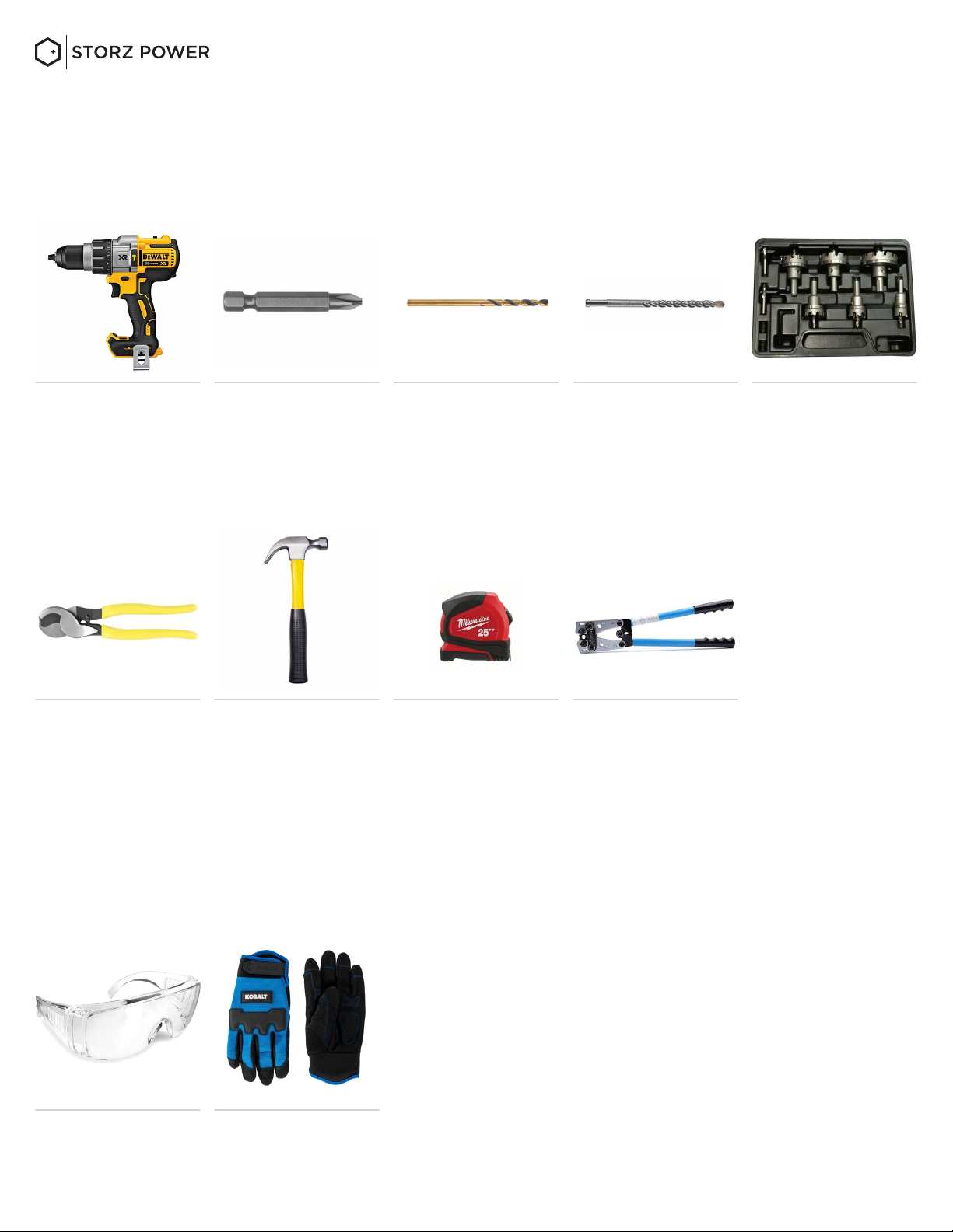
NECESSARY STORZ WALL MOUNT BATTERY CABINET INSTALLATION
TOOLS (not included in box):
RECOMMENDED PERSONAL PROTECTIVE EQUIPMENT FOR INSTALLATION
(not included in box):
• Drill with Hammer
Drill Option
• Hammer • Measuring Tape • 2/0 Crimper for
Terminal Lugs
• Safety glasses
• Philips bit
• Gloves
• 5/32” wood bit
(if installing the
cabinet on a wood-
studded wall)
• 3/8” concrete bit
(if installing the
cabinet on a
concrete wall)
• 1.5” max knockout
drillbit for metal
• 2/0 AWG
Wire strippers
STORZ WALL MOUNT BATTERY CABINET INSTALLATION MANUAL
www.storzpower.com |connect@storzpower.com |833-786-7901 |2961 W. Maple Loop Dr. Suite 300 Lehi, UT 84043

A I
pg. 6
STORZ WALL MOUNT BATTERY CABINET
You will receive the following parts:
• 5 concrete lags
(use for concrete
wall)
• 5 wood lags
(use for wood-stud-
ded wall)
• 26 x2 small screws
for both white side
panels
USE: 26 per side
• 1 red terminal
block
• 1 black terminal
block
• 4 terminal block lug
connectors
USE: 2
• 2 white flat plates
• 8 lock & flat washer
screws for attaching
red & black terminal
blocks to white flat
plates
USE: 4 per block
• 2 side panels • 1 wall bracket• 1 cabinet shell
• 2 smaller lock & flat
washer screws for
attaching ground
wire to side panels
• 8 screws for both
white flat plates
USE: 4 per plate
• 2 long screws for
wall bracket to
attach to cabinet
STORZ POWER BATTERY
You will receive the following parts with
each battery:
• Battery cables:
1 black, 1 red
• 1 comm cable
+ PACKING LIST
STORZ WALL MOUNT BATTERY CABINET INSTALLATION MANUAL
www.storzpower.com |connect@storzpower.com |833-786-7901 |2961 W. Maple Loop Dr. Suite 300 Lehi, UT 84043

A I
pg. 7www.storzpower.com |connect@storzpower.com |833-786-7901 |2961 W. Maple Loop Dr. Suite 300 Lehi, UT 84043
+ INSTALLATION
SELECTING MOUNTING LOCATION
MOUNTING THE CABINET
When installing an energy storage system, consider the following:
• The Storz Wall Mount Battery Cabinet needs to be installed on a solid vertical surface.
• The Storz Wall Mount Battery Cabinet must be installed vertically.
• The ambient temperature should be between -10°C/14°F and 55°C/131°F and the relative humidity
should be a max of 98% to ensure optimal operation.
• Do not operate in locations where the temperature and humidity are outside the specified range.
When installing the Storz Wall Mount Battery Cabinet, please use the appropriate hardware provided
to install it. After that, the equipment should be firmly bolted. The cabinet can be installed indoors or
outdoors within the specified temperature and humidity ranges. However, only professional personnel
can enter this area for installation or maintenance. Storz Power is not responsible for the use of improper
fittings that could create a leak in the Storz Wall Mount Battery Cabinet.
STEP 1
CHECK PARTS
When receiving the product, first check whether all parts are complete, if not, please report to the Dealer.
STEP 2
INSTALL LOCATION
Ensure that the cabinet is installed on a vertical wall surface. Choose an appropriate installation location.
This cabinet is designed to be installed wall mounted on a flat, vertical and structurally sound surface
with at least a 4” waterway from the ground surface. Make sure that the supporting wall surface will
safely support the weight of the equipment and all attached hardware and components.
STORZ WALL MOUNT BATTERY CABINET INSTALLATION MANUAL
WARNING!!! Please note that this cabinet is heavy, so please be careful when removing
it from the package or installing it. Storz Power will not be held responsible for damage
to equipment or personal injury resulting from improper use or installation of product
or for Storz Power products installed by an installer not Certified with Storz Power. It is
expected to use common sense when installing heavy equipment. Storz Power will not
be held liable for any personal injury during an install.

A I
pg. 8
STEP 3:
KNOCKOUT LOCATIONS
Determine which side the Battery Faceplate will face out when installed in the cabinet (left or right). Take off
the Side Panel of the side that the Battery Faceplate will be facing out. Do not lose the screws that go to the
side panel that you remove. After selecting an install location on a wall, determine where to do the 1.5” max
knockout based on wall space, how many Storz Wall Mount Battery Cabinets and Batteries are being installed,
and approved knockout locations shown in the diagram below.
5”
3” 3”
5”
3”
3” 3”
3”
TOP
Side Panels are approved
knockout locations; use only one
side if connecting conduit to
the Side Panel of the Storz Wall
Mount Battery Cabinet.
*picture above indicates for both left or
right Side Panels.
Approved knockout locations. 1.5” max. knockout size
= Battery Faceplate
Not approved knockout locations
STORZ WALL MOUNT BATTERY CABINET INSTALLATION MANUAL
www.storzpower.com |connect@storzpower.com |833-786-7901 |2961 W. Maple Loop Dr. Suite 300 Lehi, UT 84043
2”
2”

A I
pg. 9
STEP 5
INSTALL WALL MOUNT
Determine if the wall for installation is concrete or has wood studs. Follow instructions below depending
on which material the wall has. Instructions for installing onto wood studs and concrete wall are below. If
installing on brick wall, installer must provide hardware for Storz Wall Mount Battery Cabinet installation.
STEP 4
DRILL KNOCKOUT
Use up to a 1.5” knockout drillbit for
metal. Knockout drillbit must not be
any bigger than 1.5”. Drill knockout
on cabinet at an approved location.
WOOD STUDS
CONCRETE
Screw in each wood
lag, 5 total.
*picture is as it should look
once installed on the wall
*picture is as it should look
once installed on the wall
Hammer in each
concrete lag, 5 total.
Tighten bolts until
secure.
Use a 5/32” wood bit
to drill at a depth of
2.5 inches. Must be
drilled into studs.
Make sure entire
Wall Bracket is flush
& level with the
wall surface. Use all
5 wood lags, use
minimum of 2 wood
lags along top of
bracket & minimum
of 2 along bottom
of bracket. Must be
drilled into studs.
Due to variance of wall stud placements inside the walls, the Wall Mount
Bracket is allowed to be drilled to support the placement of a mounting
screw to hit a structural stud.
Use a 3/8” concrete
bit to drill at a depth
of 2.5 inches.
2. Pre-drill holes 3. Wood lags1. Select Location
1. Select Location 3. Concrete lags2. Pre-drill holes
STORZ WALL MOUNT BATTERY CABINET INSTALLATION MANUAL
www.storzpower.com |connect@storzpower.com |833-786-7901 |2961 W. Maple Loop Dr. Suite 300 Lehi, UT 84043
Make sure entire
Wall Bracket is flush
& level with the
wall surface. Use
all 5 concrete lags,
use minimum of 2
concrete lags along
top of bracket &
minimum of 2 along
bottom of bracket
for concrete wall.
TOP
TOP
BOTTOM
BOTTOM

A I
pg. 10
Attach Storz Wall Mount Battery Cabinet Shell to the Wall Mount Bracket on the wall. It
is recommended to use two Storz Power Certified Installers to lift the cabinet onto the
Wall Mount. Negligence or failure to use safety precautions as an installer due to the
weight of the cabinet while lifting is not the responsibility of Storz Power. Storz Power
will not be held liable for any lack of common sense or personal injury during installation.
Make sure Wall Mount Bracket is secured onto Cabinet Shell properly with the 2 long
screws to hold it in place on the bottom two locks on the Cabinet Shell.
STORZ WALL MOUNT BATTERY CABINET INSTALLATION MANUAL
www.storzpower.com |connect@storzpower.com |833-786-7901 |2961 W. Maple Loop Dr. Suite 300 Lehi, UT 84043
2 long screws for wall
bracket to attach to
cabinet
1 wall bracket
1 cabinet shell
STEP 6
INSTALL STORZ POWER WALL MOUNT BATTERY CABINET

A I
STORZ WALL MOUNT BATTERY CABINET INSTALLATION MANUAL
www.storzpower.com |connect@storzpower.com |833-786-7901 |2961 W. Maple Loop Dr. Suite 300 Lehi, UT 84043
STEP 7
BATTERY PREP
Remove 6 screws on each side to remove flanges from the battery(ies).
MUST: Screw the 6 screws back into battery(ies) without the flanges on each
side. DO NOT skip this step.
pg. 11

A I
pg. 12
STORZ WALL MOUNT BATTERY CABINET INSTALLATION MANUAL
www.storzpower.com |connect@storzpower.com |833-786-7901 |2961 W. Maple Loop Dr. Suite 300 Lehi, UT 84043
STEP 8
ATTACHING THE FLAT WHITE PLATES TO THE CABINET
Choose which side of the cabinet the battery faceplates will face out. Attach each white flat plate
to the cabinet with the flattest side facing out, specifically on the side of the cabinet the battery
faceplates will face out.
White Flat Plate White Flat Plate Screws for both
white flat plates
USE: 4 per plate
Battery Faceplate
There are holes that are wider
than the others on one edge;
the wider ones attach to the
top, marked in red below.
Attach both white flat plates to
the backside AND front side of
the cabinet from the inside using
the 8 screws provided; 4 screws
per white flat plate, using the
most outer edge holes.
There is a front and a back
side. The picture shown above
is the front side, which faces
out; it is the flattest side.
TOP
BOTTOM
FRONT
8a. TOP VS. BOTTOM 8c. SCREW WHITE FLAT
PLATES ONTO CABINET
8b. FRONT VS. BACK

A I
pg. 13
It is recommended to use two Storz Power Certified Installers to lift each Battery onto
each shelf of the Storz Wall Mount Battery Cabinet. Negligence or failure to use safety
precautions as an installer due to the weight of the Battery while lifting is not the
responsibility of Storz Power. Storz Power will not be held liable for any lack of common
sense or personal injury during installation. Carefully load each Battery into the Storz
Wall Mount Battery Cabinet, pushing the Storz Power Battery all the way in leaving no
space between the opposing Side Panel and the back of the Storz Power Battery.
Single Shelf Use:
Load the 1 battery onto the bottom shelf
with terminals on bottom.
Both Shelves in Use:
*Bottom Shelf MUST be loaded first
Bottom Shelf: Terminals should be on bottom
Top Shelf: Terminals should be on bottom
STORZ WALL MOUNT BATTERY CABINET INSTALLATION MANUAL
www.storzpower.com |connect@storzpower.com |833-786-7901 |2961 W. Maple Loop Dr. Suite 300 Lehi, UT 84043
STEP 9
LOADING CABINET WITH BATTERIES

A I
STORZ WALL MOUNT BATTERY CABINET INSTALLATION MANUAL
1 red terminal block1 black terminal block
8 lock & flat washer screws for attaching red &
black terminal blocks to white flat plates
Note, result from installation:
Black Terminal block should be installed on the same side as the black terminal on the Battery.
Red Terminal block should be installed on the same side as the red terminal on the Battery.
STEP 10
ATTACHING THE BLACK AND RED TERMINAL BLOCKS
Using the inside holes on the White Flate Plate already attached to the cabinet you installed in Step
8, attach the Black Terminal Block to the inside left side of the Cabinet Shell with 4 lock & flat washer
screws; the single biggest screw on the Terminal Block should be on top & the smaller two screws on
the Terminal Block should be on bottom. Repeat install instructions for the Red Terminal Block to be
attached to the inside right side of the cabinet.
TOP
BOTTOM
www.storzpower.com |connect@storzpower.com |833-786-7901 |2961 W. Maple Loop Dr. Suite 300 Lehi, UT 84043 pg. 14
STEP 11
INSTALL ADDITIONAL STORZ WALL MOUNT BATTERY CABINETS
Repeat steps 1 through 10 for additional Storz Wall Mount Battery Cabinets.

A I
STORZ WALL MOUNT BATTERY CABINET INSTALLATION MANUAL
STEP 12
ATTACHING TERMINAL BLOCK LUG CONNECTORS & BATTERY CABLES TO TERMINAL BLOCKS
Connect Storz Power Batteries properly, according to the instructions given in the Storz Power ESS
Installation Manual.
*IMPORTANT NOTE: All cables necessary for installing batteries and connecting them to other Cabinets or the Inverters are
not shown in the pictures below.
4 terminal block lug
connectors
USE: 2
1 red terminal block1 black terminal block
12a. Remove & save the plastic covers from
Terminal Blocks and Batteries; DO NOT lose, break,
or throw away the plastic covers.
Battery cables:
1 black, 1 red
SMALLER
(battery end)
SAME CABLE
BIGGER
(terminal block end)
12c. The supplied Battery Cables have two different
size lugs attached. The larger diameter lug attaches
to one of the bottom screws of the Terminal Block,
the smaller diameter lug attaches to one of the
Battery lugs. Battery Cables should be leading
downward from the Terminal Block. For second
battery, repeat step for other Black Battery Cable.
12d. Repeat steps 12b & 12c for the Red Terminal
Block and Red Battery Cable(s).
12b. Unscrew the 3 big screws that are on the
middle of the Black Terminal Block, circled in yellow
above; DO NOT lose or throw away these screws.
12e. Determine which size Terminal Block Lug
Connector is needed for both sides. Use the same
size on both sides. Attach & crimp Terminal Block
Lug Connector to the wire used to connect to
Inverter or Bus Bar (wire not provided by Storz
Power).
12f. Attach 1 Terminal Block Lug Connector to the
top big screw on the Black Terminal Block with the
wire routed upwards and use the one bigger screw
taken off in step 12b. to screw it back on.
www.storzpower.com |connect@storzpower.com |833-786-7901 |2961 W. Maple Loop Dr. Suite 300 Lehi, UT 84043 pg. 15

A I
STORZ WALL MOUNT BATTERY CABINET INSTALLATION MANUAL
www.storzpower.com |connect@storzpower.com |833-786-7901 |2961 W. Maple Loop Dr. Suite 300 Lehi, UT 84043
STEP 13
PLASTIC COVERS
Reattach all plastic covers over Battery terminals
and Terminal Blocks after Battery wiring is
complete.
STEP 14
RS485 COMM CABLE
Reference the Storz Power Battery Setup
Guide. Visit Partner Portal for Comm. Cable
configuration and dip switch assignment.
*IMPORTANT NOTE: All cables necessary for installing
batteries and connecting them to other cabinets or the
Inverters are not shown in the picture below.
pg. 16

A I
pg. 17
STEP 15
GROUND WIRE
After all wiring on Storz Power Batteries
inside the Storz Wall Mount Battery Cabinet
is complete (including but not limited to
connections from the Storz Power Batteries
to the Inverter, etc.), attach the yellow/green
ground wire already dangling from inside the
Cabinet Shell to one Side Panel using one
smaller lock & flat washer screw. Make sure the
Storz Power stickers on the outside of the Side
Panel(s) are not upside down. One Side Panel
MUST HAVE a ground wire attached.
STORZ WALL MOUNT BATTERY CABINET INSTALLATION MANUAL
www.storzpower.com |connect@storzpower.com |833-786-7901 |2961 W. Maple Loop Dr. Suite 300 Lehi, UT 84043
2 smaller lock & flat
washer screws for
attaching ground
wire to side panel.
USE: 1
2 side panels

A I
pg. 18
STEP 16
ATTACH SIDE PANELS
Attach side panels. Make sure the Storz Power
Side Panel stickers are not upside down. Screw
26 screws into each Side Panel onto the
Cabinet Shell.
Follow instructions given in the Storz Power ESS Installation Manual for proper install configurations.
+ INSTALL CONFIGURATIONS
STORZ WALL MOUNT BATTERY CABINET INSTALLATION MANUAL
www.storzpower.com |connect@storzpower.com |833-786-7901 |2961 W. Maple Loop Dr. Suite 300 Lehi, UT 84043
2 side panels26 x2 small screws
for both white side
panels
USE: 26 per side

A I
pg. 19
STORZ WALL MOUNT BATTERY CABINET INSTALLATION MANUAL
www.storzpower.com |connect@storzpower.com |833-786-7901 |2961 W. Maple Loop Dr. Suite 300 Lehi, UT 84043
19.375”
18”
WEIGHT
Wall Bracket: 6.5 lbs.
WEIGHT
Cabinet without Bracket: 65.5 lbs.
18”
37.75”
12.5”
12.75” (with Wall Bracket)
SPECS
Total Weight
72 lbs.
Total Size
19.375” x 12.75” x 37.75”
Cabinet Rating
IP65 Rated
Max Capacity
2 Storz Power Batteries
Weight with 2 Storz Power Batteries
320 lbs.
Follow all warnings and instructions in this manual to
install the Storz Wall Mount Battery Cabinet properly.
Table of contents