LG Chem RESU10H StorEdge User manual

INSTALLATION MANUAL
10H

The information included in this manual is accurate at the time of publication.
However, this manual is subject to change without prior notice. In addition, the
illustrations in this manual are meant only to help explain system conguration
concepts and installation instructions.
Please note the image shown is for illustration purposes only.
Rev.1_Nov.2016

3
Contents
1 Safety 5
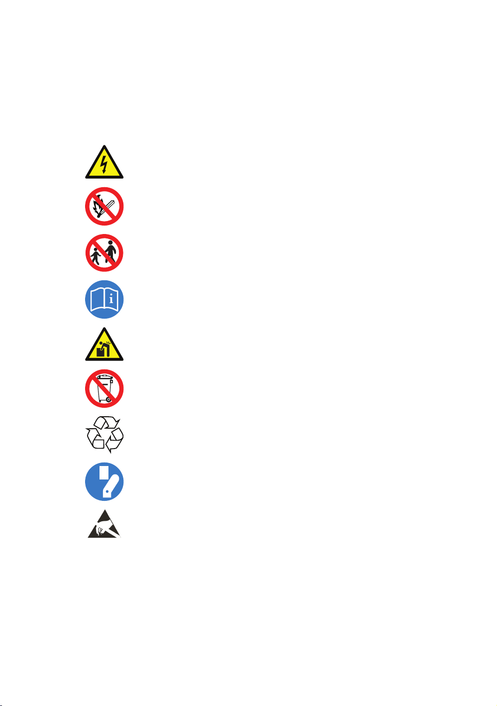
1.1 Symbols.................................................................................................................... 5
1.2 Safety instructions ................................................................................................. 6
1.2.1 General safety precautions........................................................................ 6
1.2.2 Battery handling guide.............................................................................. 6
1.2.3 Response to emergency situations ........................................................... 8
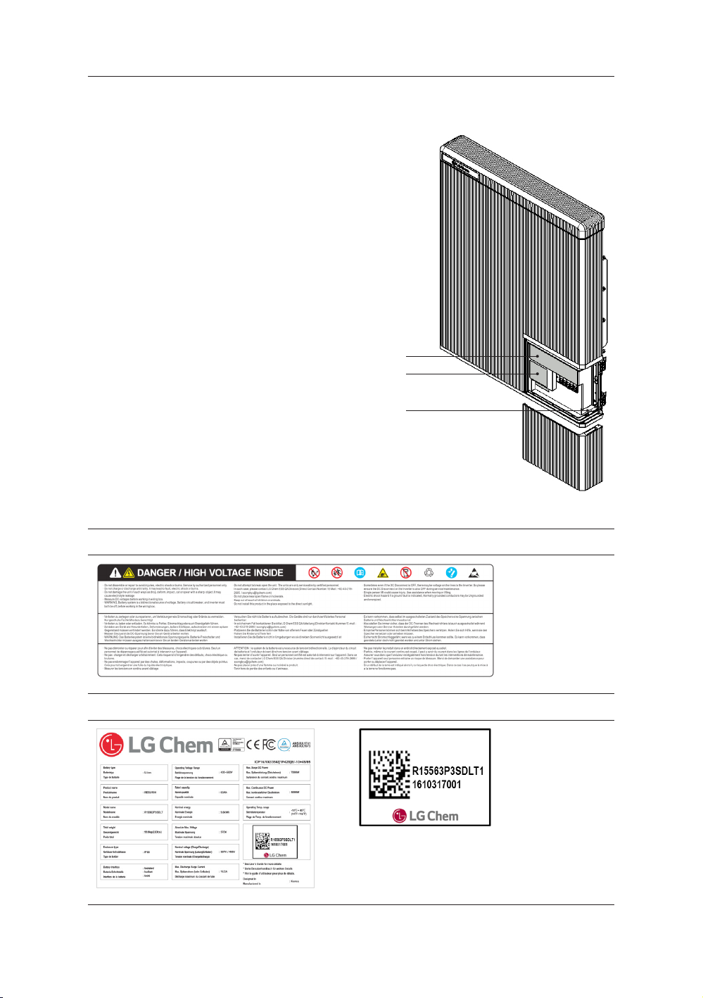
1.3 Warning label ......................................................................................................... 9
1.4 Qualied personnel............................................................................................. 10
2 Product Introduction 11
2.1 Technical data....................................................................................................... 11
2.1.1 Dimensions and weight........................................................................... 11
2.1.2 Performance............................................................................................... 12
2.2 Feature ................................................................................................................... 13
2.3 Warehouse storage instructions......................................................................... 13
2.3.1 Packaging specication............................................................................ 13
2.3.2 Handling.................................................................................................... 14
3 Installation 15
3.1 Mechanical requirements ................................................................................... 15
3.1.1 Unboxing the package.............................................................................. 15
3.1.2 Items in the package................................................................................. 17
3.1.3 Installation locations ................................................................................ 17
3.1.4 Clearance.................................................................................................... 18
3.1.5 Tools & safety gears required ................................................................. 18
3.1.6 Mounting bracket...................................................................................... 19
3.1.7 Appearance and dimension.................................................................... 21
3.1.8 System clearance....................................................................................... 21
3.1.9 Installing the battery pack....................................................................... 22
3.2 Cable connection .................................................................................................. 27
3.2.1 Spring terminal blocks............................................................................. 27
3.2.2 Connect/disconnect the wire to connector sequence.......................... 28

4
4 Commissioning 29
4.1 LED status ............................................................................................................. 29
4.1.1 LED indicators........................................................................................... 29
5 Functionality 30
5.1 Powering up the system......................................................................................30
5.2 Shutting o the system........................................................................................ 30
5.3 Emergency procedure.......................................................................................... 31
5.3.1 Fire .............................................................................................................. 31
5.3.2 Damaged or smoking batteries............................................................... 31
6 Troubleshooting 32
6.1 Troubleshooting.................................................................................................... 32
7 Uninstallation & Return 33
7.1 Return/replacement instructions ...................................................................... 33
7.1.1 Uninstallation from the wall................................................................... 33
7.1.2 Contact information .................................................................................35
Contents

5
1 Safety
1.1 Symbols
Caution, risk of electric shock
Do not place nor install near ammable or explosive materials.
Install the product out of reach of children.
Read the instruction manual before starting installation and
operation.
Heavy weight may cause serious injury to the back.
Do not dispose of the product with household wastes.
Recyclable
Disconnect the equipment before carrying out maintenance or repair.
Observe precautions for handling electrostatic discharge sensitive
devices.

6
1.2 Safety instructions
For safety reasons, installers are responsible for familiarizing themselves with the
contents of this document and all warnings before performing installation.
1.2.1 General safety precautions
which can be extremely dangerous.
install in places where explosive gas or chemicals are present.
The utility grid, solar input, and battery voltage must be disconnected from the
Battery Pack is not user serviceable. High voltage is present in the device.
The electronics inside the Battery Pack are vulnerable to electrostatic discharge.
Be sure to be grounded before handling the Battery Pack.
Read the label with Warning Symbols and Precautions, which is visibly under to the
Battery Cover (see Section 1.3)
1.2.2 Battery handling guide
• Do not expose battery to temperature over 50℃
• Do not damage the unit in such ways as dropping, deforming, impacting, cutting
• Do not connect anode and cathode terminal block opposite direction.
• Do not charge or discharge damaged battery.
• Do not place any foreign objects on the top of the Battery Pack and on the cooling
• Do not put the battery pack upside down on the ground.
•
Safety
55℃

7
• All types of breakdown of the product may lead to a leakage of electrolyte or
ammable gas.
• Do not place the product nearby ammables. It may lead to re or explosion in
case of accident.
• Keep out of reach of children or animals.
• Keep the product away from direct liquid. Do not touch or use if liquid is spilled
on the product.
• Store at cool and dry place.
(Do not storage place : Storage are for hay, straw, cha, animal feed, fertilizers,
vegetables or fruit products, greenhouse)
• Only use the product with a LGC-authorized inverter.
• Do not connect any AC conductors or Photo-voltaic conductors directly to the
battery pack and should be only connected to the Inverter
• Make sure not to accumulate snow over the battery pack or submerge battery
pack in liquids.
• Do not expose or place near water sources like downspouts or sprinklers
• If the battery pack is installed in the garage then ensure the product is above the
height of the vehicle bumper.
• Ensure proper care is taken to keep o any foreign object on top of the battery
pack
• The RESU battery pack has been certied IP55 and can be installed indoors as
well as outdoors. However, if installed outdoors, do not allow the battery pack to
be exposed to direct sunlight and water source as it may cause :
-Power limitation phenomena in the battery
(with a resulting decreased energy production by the system)
-Premature wear of the electrical/electromechanical components and
mechanical components (gaskets)
-Reduction in performance, service life and possible damage of the battery
• Product should be installed within 6 months of manufactured date.
Safety

8
1.2.3 Response to emergency situations
• If a user happens to be exposed to internal materials of the battery cell due to
damage on the outer casing, the following actions are recommended.
Inhalation : Leave the contaminated area immediately and seek medical attention.
Eye contact : Rinse eyes with running water for 15 minutes and seek medical
attention.
Contact with skin : Wash the contacted area with soap thoroughly and seek
medical attention.
Ingestion: Induce vomiting and seek medical attention.
Safety
Eective ways to deal with accidents
On land : Place damaged battery into a segregated place and call local fire
department or service engineer.
In water : Stay out of the water and don’t touch anything if any part of the
battery, inverter, or wiring is submarged.
Do not use submerged battery again and contact the service engineer.
•
Fire ghting instructions
If fire occurs when charging batteries, if it is safe to do so, shut off the power to
charge (Shut off the circuit breaker).
When batteries are heated above 150℃, there may be a possible exlposion.
•
Fire extinguishing media
Respirator is not required during normal operations.
Use FM-200 or CO2 extinguisher for batter fire.
Use an ABC fire extinguisher, if the fire is not from battery and not spread to it
yet.
•

9
Safety
1.3 Warning label
Warning labels and other relevant labels are
attached to the inside of the battery pack.
1
2
3
1. Warning label
2. Product label 3. Traceability label

10
Safety
1.4 Qualied personnel
This guide and the tasks and procedures described herein are intended for use
by skilled workers only. A skilled worker is dened as a trained and qualied
electrician or installer who has all of the following skills and experience:
• Knowledge of the functional principles and operation of on-grid and o-grid
(backup) systems.
• Knowledge of the dangers and risks associated with installing and using electrical
devices and acceptable mitigation methods.
• Knowledge of the installation of electrical devices
• Knowledge of and adherence to this guide and all safety precautions and best
practices.

11
2 Product Introduction
2.1 Technical data
2.1.1 Dimensions and weight
RESU10H
P/N EVESPBO0100A0
Width 744 mm (29.3”)
Height 907 mm (35.7”)
Depth 206 mm (8.1”)
Weight 1) 99.8 kg (220 lbs)
1) A battery pack’s weight
varies slightly.
907
744
206

12
2.1.2 Performance
RESU10H
Electrical Characteristics
Total Energy Capacity 9.8 kWh@25°C (77°F), 100% SOE
Usable Energy Capacity 9.3kWh
Battery Capacity 63 Ah
Voltage Range Charge 468 to 550 VDC
Discharge 430 to 507 VDC
Absolute Max. Voltage 570VDC
Max. Charge/Discharge Current 10.7A@467V / 11.7A@427V
Max. Charge/Discharge Power2) 5kW
Peak Power (only discharging) 7kW for 10 sec.
Peak Current (only discharging) 16.3A@430V for 10 sec.
Communication Interface CAN
DC Disconnect Circuit Breaker
Connection Method Spring Type Connector
User interface LEDs for Normal and Fault operation
Operating Conditions
Installation Location Indoor / Outdoor (Wall-Mounted)
Operating Temperature 14 to 113°F (-10 to 45°C)
Operating Temperature (Recommended) 59 to 86°F (15 to 30°C)
Storage Temperature -22 to 131°F (-30 to 55°C)
Humidity 5% to 95%
Altitude Max. 6,562ft (2,000m)
Cooling Strategy Natural Convection
Safety Cell UL1642
Battery Pack UL1973 / CE / RCM / TUV(IEC 62619)
Emissions FCC
Class 9
Transportation UN38.3 (UNDOT)
Ingress Rating IP55
※Test Conditions - Temperature 25°C
2) LG Chem recommends 3.3kW for maximizing battery lifetime.
3) Peak Current excludes repeated short duration(less than 5 sec. of current pattern).
Product Introduction
1)
1)
3)
1) Values for Battery only.

13
2.2 Feature
• Compact Energy storage unit for domestic photovoltaic system compatibility
• Residential 400V DC battery pack system : Daily cycle residential battery system
• No Additional Devices : Aux Power and Protection Devices* Included
*Protection Devices
-Inverter interface (between Battery Pack and Inverter) : Over Voltage, Over
Current, External Short Circuit, Reverse Polarity, Inrush Current, Ground Fault
, Over Temp.
-Battery inside (between Li-Ion battery and DC/DC converter) : Internal Short
Circuit, Over Voltage, Over Current, Over Temp, Under Voltage
• Flexible installation : Indoor or Outdoor
2.3 Warehouse storage instructions
2.3.1 Packaging specication
Category Contents
Size (LxWxH) (mm) 1,120
(44") 1,100
(43") 450
(17.7") Outer Size
Qty/Box (ea) 1 1ea× 2 layers
Packaging Materials
Hard Cardboard Disposable
Wood Disposable
Wood Disposable
Weight
(kg)
Packaging 40 (88lbs) Pallet + Box + Inner
Gross 147.8(326lbs) Product + Packaging
Product Introduction

14
2.3.2 Handling
• Do not step on the product or the product package. The product may be
damaged.
• A ventilated area is strongly recommended for handling the prouct.
• Store the product on a at surface.
• There must be no ammable or explosive materials nearby.
• The temperature and humidity should be maintained at a constant level.
• There should be minimal dust and dirt in the area.
• Do not store this product in a place exposed to direct sunlight.
• Store this product out of reach of children and animals.
Product Introduction

15
3 Installation
3.1 Mechanical requirements
3.1.1 Unboxing the package
1. Lift the cover upwards to remove it.
2. Pull out other items. Take them out and check
if any item is missing. See Package items on
section 3.1.2

16
3. Remove the wall bracket guide pad &
cushioning pad.
4. Remove the side cover.
5. Pull out the battery pack using handles and
stand it up.
(Lift handles are sold optionally for this
product)
Installation
CAUTION
According to regional regulations, several people
may be required for moving equipment.

17
3.1.2 Items in the package
These items are included in the package.
Battery pack Wall bracket M6 wall mount
bolts (2EA) Manual
3.1.3 Installation locations
• The building should be designed to withstand earthquakes.
• A waterproof and properly ventilated area is recommended. (IP55)
• Install the product on a at wall.
• There must be no ammable or explosive materials nearby.
• The ambient temperature should be within the range of 14-113°F (-10-45°C).
• The temperature and humidity should be maintained at a constant level.
• There should be minimal dust and dirt in the area.
• Battery pack must be installed on walls that are upright and can support 330lbs
(150kg).
• Do not install this product in a place exposed to the direct sunlight and rain/
snow falls.
• Install this product out of reach of children and animals.
CAUTION
If the ambient temperature is outside the operating range, the battery pack stops
operating to protect itself. The optimal temperature range for the battery pack
to operate is from 15°C to 30°C. Frequent exposure to harsh temperatures may
deteriorate the performance and life of the battery pack.
Installation

18
3.1.4 Clearance
300mm
(12")
Floor
300mm
(12")
600mm
(24")
300mm
(12")
• Recommended clearances (>12") for
the left, right, top and bottom of the
product is shown in the gure for
the proper ventilation and installer
convenience.
3.1.5 Tools & safety gears required
• Tools
The following tools are required to install the battery pack :
Precision screwdriver M6 Torque wrench Inclinometer
Drill
(Min. Diameter 10mm, 0.4") Pencil or Marker
Installation

19
• Safety gears for personal protection
It is recommended to wear the following safety gears when handling the battery
pack.
Insulated gloves Safety goggles Safety shoes
3.1.6 Mounting bracket
When installing the battery pack on a wall, make sure that the wall is capable of
supporting the weight of the battery pack. (Min. 150kg)
CAUTION
Make sure that the battery pack is at all times exposed to the ambient air.
The battery pack is cooled by natural convection. If the battery pack is entirely or
partially covered or shielded, it may cause the battery pack to stop operating.
Installation

20
To mount the battery pack on a wall, take the following steps :
1. Mark the location on the wall for the holes.
2. Drill holes for fasteners in the wall.
3. Drive the fasteners through the mounting bracket into the holes.
Area 1
Area 3
Area 2
Area 4
At least 250mm
Ex)
• Recommended diameter :
10mm(0.4") Min.
• Recommended length :
70mm(2.8") Min.
• Recommended material :
Stainless steel (8.8T)
• Minimum fastener count :
4(Area1) / 2(Area2) / 4(Area3) / 2(Area4)
- Vertically
• Minimum fastener clearance : At least
250mm(10")
ex. Between Area 1’s last fastener and
Installation
Other manuals for RESU10H StorEdge
3
Table of contents
Other LG Chem Batteries Pack manuals

LG Chem
LG Chem RESU Series User manual

LG Chem
LG Chem RESU10.0H User manual

LG Chem
LG Chem RESU Series User manual

LG Chem
LG Chem RESU 6.4 EX Operating and maintenance instructions

LG Chem
LG Chem RESU7H StorEdge User manual

LG Chem
LG Chem RESU10H-R User manual

LG Chem
LG Chem RESU 6.4 EX User manual

LG Chem
LG Chem RESU7H StorEdge User manual

LG Chem
LG Chem RESU10H StorEdge User manual