Prologix SOLAR PL3730 User manual

Wheel Charger
Owner’s Manual
WARNING
Read these instructions completely before using the SOLAR Battery Charger and save them for
future reference. Before using the SOLAR Battery Charger to charge a battery, read these
instructions and the instruction manual/safety information provided by the car, truck, boat or
equipment manufacturer. Following all manufacturers’ instructions and safety procedures will
reduce the risk of accident.
Working around lead-acid batteries may be dangerous. Lead-acid batteries release explosive gases
during normal operation, charging and jump starting. Carefully read and follow these instructions for
safe use. Always follow the specific instructions in this manual and on the SOLAR Battery Charger
each time you use the SOLAR Battery Charger.
All lead-acid batteries (car, truck and boat) produce hydrogen gas which may violently explode in
the presence of fire or sparks. Do not smoke, use matches or a cigarette lighter while near
batteries. Do not handle the battery while wearing vinyl clothing because static electricity sparks
are generated when vinyl clothing is rubbed. Review all cautionary material on the SOLAR Battery
Charger and in the engine compartment.
Always wear eye protection, appropriate protective clothing and other safety equipment when
working near lead-acid batteries. Do not touch eyes while working on or around lead-acid batteries.
Always store clamps away from each other or common conductors. Improper storage of clamps
may cause the clamps to come in contact with each other, or a common conductor, which would
be hazardous if the charger was plugged into an AC outlet.
Use extreme care while working within the engine compartment, because moving parts may cause
severe injury. Read and follow all safety instructions published in the vehicle's Owner's Manual.
Batteries being charged with the SOLAR Battery Charger unit likely contain liquid acids which are
hazardous if spilled.
Failure to follow instructions may cause
damage or explosion, always shield eyes.
Read entire instruction manual before use.
WARNING
Warning: This product contains chemicals, including
lead, known to the State of California to cause
cancer, birth defects and other reproductive harm.
Wash hands after handling.
Includes information on SOLAR Model Nos. PL3730 and PL3750
Part Nos. 141-485-000, 141-488-000

2
SAFETY SUMMARY
IMPORTANT SAFETY INSTRUCTIONS
SAVE THESE INSTRUCTIONS
SAVE THESE INSTRUCTIONS – This manual contains important safety and operating instructions for Model Nos.
PL3730 and PL3750.
WARNING
Read these instructions completely before using the SOLAR Battery Charger and save them for
future reference. Before using the SOLAR Battery Charger to charge a battery, read these
instructions and the instruction manual/safety information provided by the car, truck, boat or
equipment manufacturer. Following all manufacturers’ instructions and safety procedures will
reduce the risk of accident.
Working around lead-acid batteries may be dangerous. Lead-acid batteries release explosive gases
during normal operation, charging and jump starting. Carefully read and follow these instructions for
safe use. Always follow the specific instructions in this manual and on the SOLAR Battery Charger
each time you use the SOLAR Battery Charger.
All lead-acid batteries (car, truck and boat) produce hydrogen gas which may violently explode in
the presence of fire or sparks. Do not smoke, use matches or a cigarette lighter while near
batteries. Do not handle the battery while wearing vinyl clothing because static electricity sparks
are generated when vinyl clothing is rubbed. Review all cautionary material on the SOLAR Battery
Charger and in the engine compartment.
Always wear eye protection, appropriate protective clothing and other safety equipment when
working near lead-acid batteries. Do not touch eyes while working on or around lead-acid batteries.
Always store clamps away from each other or common conductors. Improper storage of clamps
may cause the clamps to come in contact with each other, or a common conductor, which would
be hazardous if the charger was plugged into an AC outlet.
Use extreme care while working within the engine compartment, because moving parts may cause
severe injury. Read and follow all safety instructions published in the vehicle's Owner's Manual.
Batteries being charged with the SOLAR Battery Charger unit likely contain liquid acids which are
hazardous if spilled.
Failure to follow instructions may cause
damage or explosion, always shield eyes.
Read entire instruction manual before use.
WARNING
Please read and retain these instructions for the continued safe use of your new charger. This manual contains
important safety information. DO NOT OPERATE this equipment UNTIL YOU HAVE READ this safety summary!
WARNING: This product contains chemicals, including lead, known to the State of California to cause cancer,
birth defects and other reproductive harm. Wash hands after handling.

3
WARNING – Shock Hazards
1. This battery charger is intended for indoor use only. Do not expose the charger to rain or snow.
2. NEVER attempt to charge a marine (boat) battery while the boat is on or near the water. A boat
must be on a trailer and located indoors before attempting to charge its battery(s). The boat
manufacturer’s battery charging instructions must be followed exactly.
3. NEVER set the charger, output cable or clamps, or AC power cord plug in water or on wet surfaces.
4. NEVER use this charger on a pier or dock. Charger could fall in water, creating an electric shock
hazard.
5. NEVER attempt to plug in or operate the battery charger with defective or damaged wires, power
cord, or power cord plug. Have any of these parts that are defective or damaged replaced by
qualified personnel IMMEDIATELY.
6. NEVER attempt to plug in the charger or operate its controls with wet hands or while standing in
water.
7. NEVER alter the AC power cord or power cord plug provided with the battery charger.
8. NEVER use an attachment not recommended or sold by Clore Automotive for use with this specific
model battery charger. Use of such attachment may result in risk of fire, electric shock or injury to
persons.
9. NEVER operate this battery charger if it has received a sharp blow, been dropped, or similarly
damaged, until after being inspected and/or repaired by qualified service personnel.
10. NEVER disassemble this battery charger. Take the battery charger to qualified service personnel
when service or repair is needed. Incorrect reassembly may result in a risk of electric shock or fire.
11. ALWAYS plug in and unplug the AC power cord by grasping the power cord plug, NOT THE
POWER CORD, to reduce risk of damaging power cord.
12. ALWAYS unplug the battery charger from the AC outlet before attempting any cleaning or
maintenance. Turning the charger’s control(s) OFF, alone, will not remove all electricity from the
charger, and will not reduce this risk.
13. An extension cord should not be used unless absolutely necessary. Use of an improper extension
cord could result in a fire or electric shock. If an extension cord must be used, make sure that:
a. That pins on plug of extension cord are the same number, size, and shape as those of plug on charger;
b. That extension cord is properly wired and in good electrical condition; and
c. That the wire size is large enough for the length of cord as specified below:
Length of cord in feet: 25 50 100 150
AWG size of cord: 16 12 10 8
WARNING – Risk of Explosive Gases
1. Working in the vicinity of a lead-acid battery is dangerous. Batteries generate explosive gasses
during normal operations and, at an even higher level, during charging. If anything is allowed to
ignite these gasses, the battery may explode, sending pieces of the battery and extremely caustic
battery acid out in all directions and with extreme force. Since just the slightest spark is sufficient
to ignite these gasses, it is of UTMOST IMPORTANCE that you read this manual and follow the
instructions exactly, before using your battery charger.
2. NEVER operate this battery charger near any fuel tanks or gas cylinders. This charger can produce
sparks that could ignite gasses and cause an explosion.
3. NEVER attempt to permanently mount this battery charger on a marine or recreational vehicle.
4. NEVER attempt to connect this charger’s output cables directly to the battery(s) in the bilge or
engine compartment of a boat. Follow the boat manufacturer’s battery charging instructions exactly.

4
WARNING – Battery Explosion Hazards
1. NEVER connect both battery charger clamps directly to the two posts of the same battery. See
Operation Instructions for connection procedures.
2. NEVER allow the DC output clamps to touch each other.
3. ALWAYS be extra cautious to reduce the risk of dropping a metal object, such as a tool, onto or
near the battery. Doing so could produce a spark or short circuit the battery or other electrical part
that could cause an explosion.
4. NEVER operate the battery charger in a closed-in area or restrict ventilation in any way.
5. ALWAYS make sure the area around a battery is well ventilated while it is being charged. Gas can
be forcefully blown away by using a piece of cardboard or other non-metallic material as a fan.
6. ALWAYS make sure that the AC power cord is unplugged from the AC outlet or extension cord
BEFORE connecting or disconnecting the battery charger clamps, to prevent arcing or burning.
7. ALWAYS locate the battery charger as far away from the battery as the DC output cables will
permit.
8. ALWAYS twist or rock charger clamps back and forth several times on the battery post and
the other point of connection at the time of initial connection. This helps keep the clamps from
slipping off their points of connection which helps reduce the risk of sparking. DO NOT rock the
clamp connected to the battery post AFTER the second connection (at a point away from the
battery) is made or sparking may occur at the battery post.
9. ALWAYS check the cable and wire connections at the battery(s) for tightness BEFORE starting to
charge. A loose connection can cause sparks or excessive heating which could cause a battery
explosion.
10. ALWAYS make sure the battery compartment is open and well ventilated before charging.
WARNING – Moving Parts Hazards
1. NEVER connect the battery charger clamps to a vehicle when the engine is running.
2. ALWAYS stay clear of fan blades, fan belts, pulleys and other moving engine parts when working
near an engine. Moving engine parts can cause severe personal injury, including dismemberment.
3. ALWAYS make sure that the battery charger cables and clamps are positioned so they will not
come in contact with any moving engine parts.
4. NEVER wear loose clothing or long hair around moving parts because they may get caught and
cause severe injury or death.
WARNING – Burn Hazards
1. NEVER lean on or rest against the engine or cooling system parts when the vehicle is running.
2. ALWAYS stay clear of the cooling system, engine, and engine manifold. These engine
components get very hot and retain heat for a long time. Touching any of these components can
cause severe burns.
WARNING
Read these instructions completely before using the Battery Charger and save them for future
reference. Before using the Battery Charger to charge a battery, read these instructions and the
instruction manual/safety information provided by the car, truck, boat or equipment manufacturer.
Following all manufacturers’ instructions and safety procedures will reduce the risk of accident.
Working around lead-acid batteries may be dangerous. Lead-acid batteries release explosive gases
during normal operation, charging and jump starting. Carefully read and follow these instructions for
safe use. Always follow the specific instructions in this manual and on the Battery Charger each
time you use the Battery Charger.
All lead-acid batteries (car, truck and boat) produce hydrogen gas which may violently explode in
the presence of fire or sparks. Do not smoke, use matches or a cigarette lighter while near
batteries. Do not handle the battery while wearing vinyl clothing because static electricity sparks
are generated when vinyl clothing is rubbed. Review all cautionary material on the Battery Charger
and in the engine compartment.
Always wear eye protection, appropriate protective clothing and other safety equipment when
working near lead-acid batteries. Do not touch eyes while working on or around lead-acid batteries.
Always store clamps away from each other or common conductors. Improper storage of clamps
may cause the clamps to come in contact with each other, or a common conductor, which would
be hazardous if the charger was plugged into an AC outlet.
Use extreme care while working within the engine compartment, because moving parts may cause
severe injury. Read and follow all safety instructions published in the vehicle's Owner's Manual.
Batteries being charged with the Battery Charger unit likely contain liquid acids which are
hazardous if spilled.
Failure to follow instructions may cause
damage or explosion, always shield eyes.
Read entire instruction manual before use.
WARNING

5
PERSONAL PRECAUTIONS
1. Someone should be within range of your voice or close enough to come to your aid when you work near a
lead-acid battery.
2. Have plenty of fresh water and soap nearby in case battery acid contacts skin, clothing or eyes.
3. Wear complete eye protection and clothing protection. Avoid touching eyes while working near battery.
4. If battery acid contacts skin or clothing, wash immediately with soap and water. If acid enters eye,
immediately flood eye with running cold water for at least 10 minutes and get medical attention
immediately.
5. NEVER smoke or allow a spark or flame in vicinity of battery or engine.
6. Be extra cautious to reduce risk of dropping a metal tool onto battery. It might spark or short-circuit
battery or other electrical part that may cause explosion.
7. Remove personal metal items such as rings, bracelets, necklaces and watches when working with a lead-
acid battery. A lead-acid battery can produce a short-circuit current high enough to weld a ring or other
jewelry to metal, causing a severe burn.
8. Use charger for charging LEAD-ACID batteries only. It is not intended to supply power to a low voltage
electrical system other than in a starter-motor application. Do not use battery charger for charging dry-cell
batteries that are commonly used with home appliances. These batteries may burst and cause injury to
persons and damage to property.
9. NEVER charge a frozen battery, as battery explosion can result.

6
TABLE OF CONTENTS
SAFETY SUMMARY
Safety Information........................................................................................................................................................................................ 2
Shock Hazards...........................................................................................................................................................3
Explosive Gas Hazards..............................................................................................................................................3
Battery Explosion .......................................................................................................................................................4
Moving Parts Hazards................................................................................................................................................4
Burn Hazards .............................................................................................................................................................4
Personal Precautions .................................................................................................................................................5
INTRODUCTION
Description ................................................................................................................................................................................................... 8
How Batteries Charge................................................................................................................................................................................... 8
Deeply-discharged Lead-Calcium Batteries................................................................................................................................................. 8
Spark Prevention.......................................................................................................................................................................................... 8
ASSEMBLY
Assemble the Handle.................................................................................................................................................................................... 9
PREPARATION
Charger Placement..................................................................................................................................................................................... 10
Provide Required Power............................................................................................................................................................................. 10
Extension Cords.......................................................................................................................................................10
Battery Preparation .................................................................................................................................................................................... 11
The Ability to Charge Multiple Battery Types............................................................................................................................................. 11
Soft Start Mode and Battery Repair Mode ................................................................................................................................................. 11
Change Display Language.......................................................................................................................................................................... 11
CONTROLS AND INDICATORS
LCD Display ................................................................................................................................................................................................ 12
Function Selection Button .......................................................................................................................................................................... 12
Function Control Buttons............................................................................................................................................................................ 12
LED Status Lights ....................................................................................................................................................................................... 12
Choosing the Operating Voltage and Charge Rate ..................................................................................................................................... 13
Choosing a Battery Type Setting................................................................................................................................................................ 13
Pre-Charge Battery Activation.................................................................................................................................................................... 13

7
OPERATION
Operating Instructions................................................................................................................................................................................ 14
Connecting to Batteries Installed in Vehicles...........................................................................................................14
Connecting to Batteries Outside a Vehicle ..............................................................................................................14
Operational Sequences and Screen Progressions ..................................................................................................................................... 15
Auto Mode Charging Sequence...............................................................................................................................15
Stable Power Mode Sequence ................................................................................................................................17
Engine Starting Sequence .......................................................................................................................................18
MAINTENANCE
Maintenance............................................................................................................................................................................................... 19
TROUBLESHOOTING
Troubleshooting.......................................................................................................................................................................................... 19
LIMITED WARRANTY
Limited Warranty........................................................................................................................................................................................ 20

8
INTRODUCTION
Description
This battery charger is designed to handle the majority of your charging and starting needs. It features:
• Automatic Multi-Phase Charging mode for easy operation.
• The ability to properly charge multiple battery types, including flooded, AGM and Gel Cell.
• Multiple Charge Rates for various battery sizes.
• High-Amperage Engine Starting Assistance to start vehicles when the battery is weak.
• A digital display that provides a wealth of information during the set-up, operating and completion
phases of the charging or starting processes.
• A stable power mode to maintain vehicle system voltage during on-vehicle repairs.
• Large Saw-Tooth Clamps assure good connection to top or side-mount battery terminals.
• Heavy-Duty Construction for long, trouble-free life.
How Batteries Charge
A battery charger does not force current into a battery – it makes a specific amount of current available to the
battery and the battery draws as much of it as it needs, up to or slightly greater than the rated output current
capability of the charger.
The closer a battery is to zero capacity (dead battery), the more charging current it will want to draw. When
charging begins, on a dead battery, the charger will typically supply current at or very near the nominal chosen
charging rate, and then move to a reduced rate of current as the battery becomes more fully charged. Keep in
mind, a charger’s display shows the amount of current being drawn from the charger by the battery, not what the
charger is capable of delivering.
One would expect a battery to draw zero amps when it reaches 100% charge. But at 100% charge, a battery
charged in Manual Mode will continue to draw a low level of current and convert it into heat within the battery.
If left connected and charging after reaching 100% charge, the battery acid will begin to boil, may produce acid
vapor and get hot, resulting in overcharging and possible battery damage.
The Automatic Mode available on PRO-LOGIX Wheel Charger models eliminates this issue and prevents any
damage to the battery due to overcharging. Whenever practical, the operator should choose Automatic Mode
charging to ensure a proper charge and prevent overcharging.
Note: A slow, intermittent bubbling sound may be heard coming from the battery during the charging process. This is
a normal condition and just another indicator the battery is being charged.
To reduce the risk of battery overcharging, it is important to thoroughly read this entire instruction manual.
Deeply-Discharged Lead-Calcium Batteries
Many newer automotive batteries are of a lead-calcium plate design. When deeply discharged, they may require an
activation period before accepting a measurable charge. This activation period may take as long as 4 to 8 hours.
If, at the beginning of the charging process, you notice that the ammeter is at or near zero, but you have
determined that the battery is very discharged (less than 25% of charge), this is a good indication that an activation
period is required (see Pre-Charge Battery Activation).
Spark Prevention
Make sure no sparks or flames occur near the battery, especially during charging. It takes very little to ignite the
explosive gasses produced by a lead-acid battery during the charging process. Read, understand and follow the
safety information provided in the Safety Summary section of this manual before attempting to work with or near a
lead-acid battery.
For more information about batteries and battery charging, contact Battery Council International at
www.batterycouncil.org, and download their Battery Service Manual.
9
ASSEMBLY
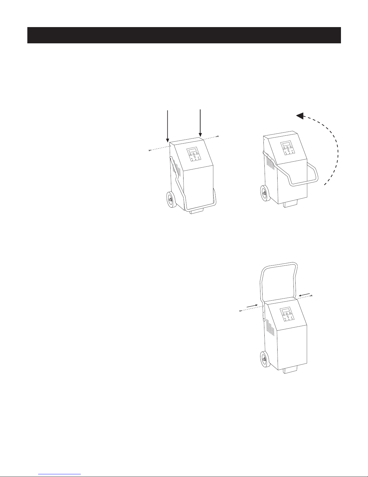
Assemble the Handle
Assemble the charger handle according to the following instructions and illustrations.
1. Carefully remove the charger
unit and all associated
hardware from carton.
2. Unscrew the two screws on
either side of the charger as
shown in Figure 1. They are
the screws nearest to the
top and towards the rear
of the unit.
3. The charger is shipped with the handle partially secured
and resting in a down position on the front of the unit.
Lift the handle on its axis, up and over the front of the
charger into a vertical position, perpendicular to the top
of the unit.
4. Align the holes in the handle with the screw holes on the
side of the charger (the same holes from which you just
removed the two screws in step 2). Secure the two screws
back into their original holes, thus securing the handle
(Figure 3).
Figure 1. Remove the screws
Remove the Screws
Figure 2. Lift the handle
Lift the Handle Into Position
Figure 3. Secure the handle
Secure the Handle

10
Charger Placement
Place the charger in a clean, dry, stable, well-ventilated spot as far from the battery as the DC output cables
permit.
NEVER place the charger directly above the battery being charged - gasses from the battery will corrode and
damage the charger.
NEVER allow battery acid to drip on the charger when reading specific gravity or filling the battery.
NEVER place a battery on top of the charger.
NEVER attempt to permanently mount this battery charger on a marine or recreational vehicle.
ALWAYS position the charger on the outside of a boat or recreational vehicle.
Provide Required Power
This battery charger requires a nominal 120V 60Hz alternating current (AC) power source. The power source must
be fused at an amperage greater than or equal to the input amps rating of this charger - see back of unit for input
power requirements.
Do not plug the charger into the AC power source until told to do so in the operating instructions.
WARNING: ELECTRIC SHOCK CAN KILL!
See Safety Summary, pages 2-5.
To reduce risk of electric shock, never alter AC power cord or power cord plug provided on the charger. If it will
not fit the outlet, have a proper outlet installed by a qualified electrician. Never use an adapter.
The charger must be grounded to reduce risk of electric shock. The charger is equipped with an electric cord
that has an equipment grounding plug. The plug must be plugged into an AC outlet that is properly installed and
grounded in accordance with all local codes and ordinances.
Extension Cords
Note: Engine starting performance may be reduced when extension cords are used.
An extension cord should not be used unless absolutely necessary. If necessary, care must be taken to select an
extension cord suitable for use with your specific battery charger (see Shock Hazards in Safety Summary).
WARNING: Fire can kill, injure and cause property damage!
See Safety Summary, pages 2-5.
To reduce risk of electric shock and fire, never alter the AC power cord or power cord plug provided on the
charger. Never alter extension cords or extension cord plugs. Make sure the extension cord is properly wired and
in good electrical condition. Make sure the wire size (American Wire Gauge or AWG) of the extension cord is large
enough to handle your specific charger’s amperage requirements. This battery charger features protection against
abnormally low input voltage and will safely shut the charger down if input voltage is too low.
Battery Preparation
WARNING: Battery explosion can injure and cause property damage! Never smoke or allow a spark
or flame in the vicinity of the battery or engine.
See Safety Summary, pages 2-5.
If it is necessary to remove the battery from the vehicle to charge it, make sure all accessories in the vehicle are off
and always remove the grounded cable from the battery first.
If needed, add distilled water to each cell of the battery until battery acid reaches the manufacturer’s specified
level. DO NOT OVERFILL! This helps remove excessive explosive gasses from the battery. For maintenance free
batteries without caps, carefully follow the battery manufacturer’s recharging instructions.
WARNING
Read these instructions completely before using the Battery Charger and save them for future
reference. Before using the Battery Charger to charge a battery, read these instructions and the
instruction manual/safety information provided by the car, truck, boat or equipment manufacturer.
Following all manufacturers’ instructions and safety procedures will reduce the risk of accident.
Working around lead-acid batteries may be dangerous. Lead-acid batteries release explosive gases
during normal operation, charging and jump starting. Carefully read and follow these instructions for
safe use. Always follow the specific instructions in this manual and on the Battery Charger each
time you use the Battery Charger.
All lead-acid batteries (car, truck and boat) produce hydrogen gas which may violently explode in
the presence of fire or sparks. Do not smoke, use matches or a cigarette lighter while near
batteries. Do not handle the battery while wearing vinyl clothing because static electricity sparks
are generated when vinyl clothing is rubbed. Review all cautionary material on the Battery Charger
and in the engine compartment.
Always wear eye protection, appropriate protective clothing and other safety equipment when
working near lead-acid batteries. Do not touch eyes while working on or around lead-acid batteries.
Always store clamps away from each other or common conductors. Improper storage of clamps
may cause the clamps to come in contact with each other, or a common conductor, which would
be hazardous if the charger was plugged into an AC outlet.
Use extreme care while working within the engine compartment, because moving parts may cause
severe injury. Read and follow all safety instructions published in the vehicle's Owner's Manual.
Batteries being charged with the Battery Charger unit likely contain liquid acids which are
hazardous if spilled.
Failure to follow instructions may cause
damage or explosion, always shield eyes.
Read entire instruction manual before use.
WARNING
PREPARATION

11
WARNING: Battery acid can cause serious injury and property damage!
See Safety Summary, pages 2-5.
Always wear complete eye and clothing protection and avoid touching eyes while working near battery.
Clean battery terminals. Be careful to keep corrosion from coming in contact with eyes.
Study all of the battery manufacturer’s precautions, such as whether cell caps should be left in place or removed
during charging, and the recommended rates of charge for the specific battery. If you are unable to determine the
battery manufacturer’s requirements for charging, always charge the battery with cell caps in place at the lowest
charging rate available.
If the battery voltage cannot be determined from the information on the battery itself, refer to the owner’s manual
for the product in which the battery was installed.
The Ability to Charge Multiple Battery Types
Traditional battery chargers utilize basic charging controls that make them appropriate for charging only
Conventional and Maintenance Free Flooded (wet) Cell batteries. Use of traditional battery chargers on AGM, Gel
Cell or other modern batteries results in suboptimal charging and potential harm to the battery being charged.
PRO-LOGIX Wheel Charger models utilize advanced charging technology to deliver precise charge controls,
enabling them to properly charge a wide variety of battery types.
Soft Start Mode and Battery Repair Mode
PRO-LOGIX Wheel Charger models utilize a proprietary advanced Multi-Phase charging process designed to
optimally charge many types of batteries. One critical aspect of this proprietary process is the precise control
achieved through the charging process, enabling the charger to monitor a battery’s specific reaction to the power
supplied. The PRO-LOGIX charging process includes a Soft Start Mode to properly charge deeply discharged
batteries and ensure that the energy from the charger is being properly incorporated into the battery. It also
includes a Battery Repair Mode to attempt to restore batteries that do not properly accept charging current. The
display will indicate BATTERY REPAIR and monitor current acceptance by the battery. Battery charging time will be
extended to allow the battery to recover. Both processes are fully automatic and require no intervention on the part
of the operator, either to initiate the process or complete it.
Change Display Language
With the unit in the OFF position, depress and hold the TOGGLE button down. Turn unit ON. This will bring you to
the language set up screen. Use the SELECT button to choose language and press START to return to the main
screen.

12
LCD Display
The LCD display provides detailed information needed to
set up each of the three functional options of the charger. In
addition, the display will provide detailed status information
as each function is performed.
For instance, during the set-up process for Automatic Mode
charging, the display will provide information regarding
the different charging parameters available, such as what
battery type is to be charged and the desired charging rate
for that charging instance. Once the charging sequence has
commenced, the display will provide specific details related
to charging progress. The information displayed changes
depending on the type of charging mode the user has
selected.
The display has a backlight for better viewing in low light
conditions. The backlight will turn off if the charger is idle and
not charging for more than 15 minutes. If the backlight is off,
the first button pressed will only turn the backlight on. The
next button pressed will perform its normal function.
FUNCTION Selection Button
The FUNCTION selection button changes the mode of
operation of the charger between AUTO CHARGE mode,
STABLE POWER mode and ENGINE START mode. In Auto
Charge mode, once the charging parameters have been set
and the START button has been pressed, the charger will
commence a proprietary, advanced Multi-Phase charging sequence designed to provide an optimal charge.
STABLE POWER mode provides steady, stable power to maintain system voltage during on-vehicle repairs
and other applications where it is detrimental should system voltage drop below a specific threshold. ENGINE
START mode provides engine starting assistance to jump start vehicles with depleted batteries.
FUNCTION Control Buttons
FUNCTION control buttons allow an operator to sequence through the parameters related to each function,
choose specific values for those parameters and commence the chosen function. They include the following
buttons: TOGGLE, SELECT and START.
The TOGGLE button is used to sequence through the various parameters related to each function. For
instance, during Auto Mode charging, the operator can toggle through voltage options, battery type options
and charge rate options. The SELECT button is used to choose a specific value for an available parameter
within a function. For instance, during Auto Mode charging, the operator can choose 60A, 40A, 15A or 5A
charge rates when in 12V mode. The START button is used to commence each function once all of the
functional parameters have been set to the desired values. The START button can also be used to discontinue
any function once it has commenced.
LED Status Lights
LED lights in the control panel indicate which functional mode the charger is currently set to, as well as current
status of the chosen function once the function has commenced. In addition, an error LED alerts the operator
to unsafe charging conditions, including battery faults and reverse polarity connection.
CONTROLS AND INDICATORS

13
Choosing the Operating Voltage and a Charging Rate
Always set the Operating Voltage for any function to match the voltage of the battery/system to which the charger
is connected. If the battery voltage is not clearly marked on the battery, refer to the operator’s manual for the
vehicle/equipment where the battery is used/intended to be used. NEVER begin charging if the battery voltage
cannot be determined.
Choose a charging rate that is appropriate for the size and type of battery being charged. Use the battery
manufacturer’s specific instructions or see the guidelines below.
Typical rates are:
Small Motorcycle/Powersport 5 Amps or less
Lawn Mower/Tractor 5 Amps or less
Deep Cycle 15 Amps or less
Maintenance Free Automotive or Marine Cranking 40 Amps or less
Heavy Duty Commercial 60 Amps or less
Do not exceed the maximum charge rate recommended by the battery manufacturer or the chart above.
Unless the information is supplied for the particular battery, always charge small batteries at no more than 5 Amps.
If the battery requires charging at less than 5 Amps, do not attempt to charge such batteries using this charger.
Choosing a Battery Type Setting
PRO-LOGIX Wheel Charger models utilize advanced charging technology to deliver precise charge controls,
enabling them to properly charge a wide variety of battery types.
• For Conventional and Maintenance Free Flooded (wet) Cell batteries: Choose STANDARD.
• For AGM batteries: Choose AGM.
• For Spiral Wound Batteries: Choose AGM.
• For Gel Cell batteries: Choose GEL.
For batteries identified as Deep Cycle or Marine batteries, determine the construction of the battery. Is it a wet cell,
AGM, Spiral or Gel Cell type of construction? Battery construction will determine the proper battery type selection.
Pre-Charge Battery Activation
Some modern batteries can cause charging problems if they have been deeply discharged. The plates in these
batteries can begin sulfating quickly, forming a barrier to accepting a charge. This condition will be indicated
by an extremely low (or zero) ammeter reading, indicating that the battery is not accepting current from the
charger. A deeply discharged battery such as this may take as long as 4 to 8 hours before it will accept a charge.
The Automatic Charging mode attempts to detect batteries with this condition (see Battery Repair Mode in
PREPARATION) and automatically adjusts for it.
If you prefer to activate the battery manually, follow this procedure:
Function Select Manual Charge Mode
Specify the correct battery voltage (6/12/24V)
Specify a moderate charge rate (such as 5A or 15A).
Monitor the battery every 30 minutes. When the sulfate barrier has been broken through, the battery will begin
accepting a charge and the ammeter current will be at the 5A or 15A selected rate. The amount of time to charge
the battery fully (determined in Charging Time Instructions) begins when the battery begins accepting a charge.
Once the battery begins to accept a charge, you may return to Auto Mode charging to safely charge
your battery.

14
OPERATING INSTRUCTIONS
ATTENTION: Do not attempt to operate this battery charger until you have read and understood the entire Safety
Summary provided in this manual.
Note: Go to Assembly in this manual before proceeding with the operation of your battery charger. Do not attempt to
operate the charger until all required user-assembly is completed.
Connecting to Batteries Installed in Vehicles
ATTENTION: Do not plug the charger power cord into the AC power source or set any of the charger’s controls
until told to do so in the following instructions.
ATTENTION: Connect and disconnect DC output clips only after setting any charger switches to “OFF” position
and removing AC cord from electric outlet. Never allow clips to touch each other.
1. Make sure that the AC power cord is unplugged from the AC outlet and make sure the vehicle’s engine is
turned off.
2. Position the AC power cord and DC output cables in such a manner that they cannot be damaged by
moving engine parts or the vehicle’s hood or doors.
3. Check the polarity of the battery terminals. The POSITIVE terminal should be marked POSITIVE, POS, + or
P. The NEGATIVE terminal should be marked NEGATIVE, NEG, – or N.
4. Determine whether the vehicle has a positive or negative grounded battery (positive or negative cable is
connected to the vehicle’s chassis).
WARNING: Moving engine parts can cause serious injury! Stay clear of fan blades, belts, pulleys and
other moving engine parts to reduce risk of serious personal injury.
a. Negative Ground Vehicles (most common, see Figure 5)
1) Connect the POS (red, +) clamp from the battery charger to the
POS, ungrounded terminal of the battery.
2) Connect the NEG (black, –) clamp from the battery charger to a
heavy gauge metal part of the vehicle chassis or engine block away
from the battery. DO NOT connect the NEG charger clamp to the NEG
battery terminal, carburetor, fuel lines or sheet metal body parts.
b. Positive Ground Vehicles
1) Connect the NEG (black) charger clamp to the NEG, ungrounded
terminal of the battery.
2) Connect the POS (red) charger clamp to a heavy gauge metal part
of the vehicle chassis or engine block away from the battery. DO NOT
connect the POS (red) charger clamp to the POS battery terminal, carburetor, fuel lines or sheet metal
body parts.
5. When disconnecting charger, turn switches to off, disconnect AC cord, remove clip form vehicle chassis
and then remove clip from battery terminal.
Connecting to Batteries Outside a Vehicle
1. Make sure that the AC power cord is unplugged from the AC
power source.
2. Check the polarity of the battery terminals (see Figure 6). The
POSITIVE terminal should be marked POSITIVE, POS, + or P. The
NEGATIVE terminal should be marked NEGATIVE, NEG, – or N.
3. Attach a battery or booster cable, AT LEAST 24 inches long, that
is the same (or larger) wire gauge as the charger cable, to the
NEGATIVE terminal of the battery.
WARNING: Battery explosion can injure, and cause property
damage! To reduce the risk of battery explosion, NEVER
connect both battery charger clamps directly to the two posts of a battery.
Negative
Ground Vehicle
Negative to
Chassis Ground
Positive
Figure 5.
Connecting Outside a Vehicle
From
Charger
Positive (+)
Charger
Cable
Negative (ñ)
Charger
Cable
Booster
Cable
Figure 6.
OPERATION

15
4. Connect the POS (red) charger clamp to the POS battery terminal.
5. Position yourself and the free end of the cable (attached to the NEG battery terminal) as far away from
the battery as the cable will allow. Then, WHILE FACING AWAY FROM THE BATTERY, connect the
NEGATIVE charger clamp to the free end of the cable.
6. When disconnecting charger, turn switches to off, disconnect AC cord and disconnect charger,
always in reverse sequence of connecting procedure and break first connection while as far away
from battery as practical.
OPERATIONAL SEQUENCES AND SCREEN PROGRESSIONS
Auto Mode Charging Sequence
Auto Mode charging should be the most commonly used charging method, as this method most fully utilizes
the advanced technology of the charger and delivers the most beneficial charge to the battery.
First, connect the charger to the vehicle (see previous section, Connecting to Batteries...).
Once a proper connection has been made, plug the unit into an AC outlet and turn the master Power Switch to
the ON position. Press the Function Selection button until the LED corresponding to “AUTO CHARGE” is lit.
Once you have chosen “AUTO CHARGE” Function Selection, the charger will enter Auto Charge Mode. Upon
entering this mode, the display will read as follows:
AUTO CHARGE 12.3V
Voltage: 12V
Battery: STD
Rate: 15A
To select a different battery voltage, type or current, press the TOGGLE button until
value arrow flashes. Press SELECT button to find the correct selection. Press
TOGGLE again to set another value. Press TOGGLE again to exit settings.
AUTO CHARGE 12.3V
Voltage: 12V
Battery: STD
Rate: 15A
AUTO CHARGE 12.3V
Voltage: 12V
Battery: STD
Rate: 15A
AUTO CHARGE 12.3V
Voltage: 12V
Battery: STD
Rate: 15A
Once the desired value for each parameter is set, push START to begin charging. The display will switch from
set-up view to charge status view and reflect specific details of the charging progress: Operating Voltage,
Battery Type, Nominal Charge Rate, Actual Battery Voltage, Actual Charging Current (Ammeter), Battery % of
Charge and Charging Mode. An example is shown below:
CHARGING 12V GEL 5A
Voltage: 13.3V
Current: 4.7A
70% CHARGING
Observe the display for any warnings. You should see the displayed battery voltage rise, plus changes in the
charging current and an increase in the battery % of charge over time.
When charging is complete, the CHARGED LED will light. The display will show the battery voltage and signal
that the charger has entered MAINTENANCE MODE.
MAINTENANCE MODE
Voltage: 13.2 Volts
CHARGING COMPLETE

16
When an abnormal condition is detected in the battery, the charger may switch to one of several special charging
modes to overcome the detected abnormal condition or enter standby mode and flash a warning on the display to
explain why charging is suspended. Below are conditions that cause the charger to interrupt Auto Mode charging.
If the battery has a low starting voltage (<10.5V), the charger will automatically enter SOFT START
mode. This mode reduces the charging current to 5 Amps to allow the battery to recover from a deep
discharge, before resuming Normal Auto Mode charging once battery voltage rises to a normal value.
Below is an example of the display in SOFT START Mode.
CHARGING 12V STD 15A
Voltage: 9.3V
Current: 4.5A
5% SOFT START
Press SEL
To See
SOFT START MODE
5A Charge Limit
Battery Voltage
Too Low
If the battery’s voltage starts at a low value and increases extremely rapidly, the charger will automatically
enter BATTERY REPAIR Mode. BATTERY REPAIR Mode reduces the charge rate to no more than 10 Amps
and maintains an elevated charging voltage to allow the battery to recover its capacity to be charged fully.
After the battery begins to accept normal charging current, Normal Auto Mode charging automatically
resumes. Below is an example of the display in BATTERY REPAIR Mode.
BATTERY REPAIR MODE
Poor Battery Condition
Max Charge Rate: 10A
If the charger continues in BATTERY REPAIR Mode for 6 hours without the battery accepting normal
charging current, charging will stop and the fault light will be lit. Below is an example of the display after a
BATTERY REPAIR timeout.
Battery will not
accept a charge.
Charging Stopped!
The charger incorporates Smart Clamp Technology and will send power to the output leads only when a
proper battery connection is detected. If an incorrect connection is detected, the fault light will be lit and an
error message will appear on the display. Below is an example of the display when the charger detects an
improper connection.
*********Warning*********
Battery Cables
Reversed
Sometimes a deeply discharged battery can cause the charger to determine there is no battery connected
(or that the battery is shorted) and prevent the charger from starting Auto Mode charging. This safety
mechanism can be overridden. Before proceeding, check all charger settings and vehicle connections
(remembering that you should disconnect from the AC power supply prior to disconnecting or reconnecting
the output leads). Below is an example of the display when this condition occurs.
*********Warning*********
No Battery Voltage
Detected!
Hit SEL to Override
If you have confirmed all vehicle connections and have determined that
the condition is caused by battery voltage at or near 0V, press SELECT
to override.

17
If the battery fails to reach a CHARGE COMPLETE condition within a specified time limit, charging will stop
and the FAULT light will be lit. The time limit value is determined by the charger based on the nominal
charge rate chosen. In rare cases, such as charging extremely large batteries or charging a high capacity
two battery system, the time required to reach CHARGE COMPLETE may exceed the time limit. Below is
an example of the display when this condition occurs.
Charge time exceeded.
Charging Stopped!
Confirm battery/battery bank voltage is in
the normal range. Press START to restart charging.
After charging is complete, turn off the Master Power Switch and unplug the charger from the AC power source.
Then, disconnect the charger clamp not connected directly to the battery first and DO NOT allow the clamp
to touch anything. Then, disconnect the charger clamp attached to the battery terminal. (See Connecting To
Batteries... at the beginning of this section.)
Stable Power Mode Sequence
Your PRO-LOGIX Battery Charger can also be used to supply steady power to maintain system voltage during
an on-vehicle repair. When using the charger in this mode, we recommend that the battery be fully charged. If
necessary, run a full charging cycle prior to engaging this mode. This mode will not activate if the vehicle’s battery
is below 11.0VDC. Also, this operational mode is intended for use in a wide variety of repair applications, but is not
intended for use when flash reprogramming vehicle modules.
First, connect the charger to the vehicle (see previous section, Connecting to Batteries...). Once a proper
connection has been made, plug the unit into an AC outlet and turn the master Power Switch to the ON position.
Press the Function Selection button until the LED corresponding to “STABLE POWER” is lit.
STABLE POWER 12.0V
Battery Voltage: 12V
Charge Volts: 14.4V
MAX Rate 60A
To select a different battery voltage, nominal charge voltage or charge rate, press the TOGGLE button until value
arrow flashes. Press SELECT button to find the correct selection. Press TOGGLE again to set another value.
STABLE POWER 12.0V
Battery Volts: 12V
Charge Volts: 14.4V
Max Rate 60A
STABLE POWER 12.0V
Battery Volts: 12V
Charge Volts: 14.4V
Max Rate 60A
STABLE POWER 12.0V
Battery Volts: 12V
Charge Volts: 14.4V
Max Rate 60A
Once the desired value for all parameters are set, press START to begin Stable Power mode function. The display
will switch from set-up view to operational view and reflect specific details of the Stable Power mode function. An
example is shown below:
STABLE POWER 12.0V
Voltage
Charge Volts
Note: While actively engaged in Stable Power mode, the amber
CHARGING LED will light to indicate the unit is operational.
When the unit is operating in Stable Power mode, the charger will supply stable power with a goal of maintaining
steady system voltage at the desired voltage as indicated during set-up. The charger will allow the current supplied
to the battery/system to vary as needed to the maximum amperage indicated during set-up. If there is an increase
in system need, the charger will react to it and supply as much current, up to the maximum designated, as needed
to maintain system voltage.

18
Like battery charging, if at any time during this operation, you wish to stop the charger, you can push the START
button to return the unit to Standby Mode.
After your Stable Power session is complete, press the START button to bring the unit to Standby Mode, turn off
the Master Power Switch and unplug the charger from the AC power source. Then, disconnect the charger clamp
not connected directly to the battery first and DO NOT allow the clamp to touch anything. Then, disconnect the
charger clamp attached to the battery terminal. (See Connecting To Batteries... at the beginning of this section).
Engine Starting Sequence
Your battery charger can provide a high current output to help start a vehicle with a weak battery. However, the
electronics in some vehicles can be damaged when attempting to jump start. ALWAYS READ THE VEHICLE
OPERATOR’S MANUAL BEFORE AUXILLIARY STARTING to determine if jump starting can do damage to the
vehicle. If not, read and follow these instructions.
First, connect the charger to the vehicle (see previous section, Connecting to Batteries...). Once a proper connection
has been made, plug the unit into an AC outlet and turn the Master Power Switch to the ON position. It is
recommended to charge the battery for 5 to 10 minutes, remembering to always follow the recommended values
for charging rate and battery type found in the Controls and Indicators section of this manual for each battery to be
charged. Charge according to the steps identified in the Auto Charging Sequence section of this manual. After 10
minutes, press START to stop charging and enter idle mode.
Press the Function Selection button until the LED corresponding to “ENGINE START MODE” is lit.
Once you have chosen “ENGINE START MODE” Function Selection, the charger will enter Engine Start Mode.
Upon entering this mode, the only operator-defined parameter is Operating Voltage. Use the TOGGLE and SELECT
buttons to identify the voltage that matches the vehicle’s operating voltage – available only in 6V and 12V operation
voltages.
ENGINE START MODE 12.0V
Voltage: 12V
Press START
Start Vehicle
CAUTION: Do not try to boost start a vehicle that
does not contain a battery or you may damage
electrical systems in the vehicle.
Press START to activate Engine Start Mode. Because Engine Start Mode can provide excessive current to the
battery, it is active for 2 minutes from the time START is pressed. After 2 minutes, the charger will return to idle
mode. Below is an example of the display in Engine Start Mode.
STARTING 12 Volt 118s
Voltage: 12.0V
Press START again to
deactivate Boost
CAUTION: Remember to follow the duty cycle! If the vehicle
doesn’t start after 5 seconds, stop and wait for 4 minutes.
The charger is equipped with a safety mechanism that limits
crank duration to protect internal components.
When complete, press START again to deactivate Engine Start Mode. Engine Start Mode has a time limit to prevent
overheating in the charger. If the limit is exceeded, the unit will be in Cool Down mode until it is safe to return to
Engine Start Mode. When the charger is in Cool Down mode, the display will flash the below message:
Cool Down Mode
Voltage: OFF
Waiting: XXX seconds
(Safe to disconnect)
Note: If the engine spins but fails to start after several starting attempts, there is an engine problem not related to the
starting system. Discontinue cranking the engine until the other problem is found and corrected.
Engine Start Mode also has built-in safety logic that deactivates this mode if the charger senses that the voltage of
the vehicle battery and the chosen charger operating voltage do not match. An example is shown below:

19
MAINTENANCE
CAUTION: Make sure charger is unplugged from AC outlet before performing any cleaning or maintenance.
1. Clean the clamps after each use. Wipe off any battery fluid that may have come in contact with the clamps
to prevent corrosion. Battery fluid may be neutralized with a solution of water and baking soda.
2. Coil the input and output cables neatly after each use. This will help prevent damage to the cables and the
charger.
3. If needed, the case may be wiped clean with a soft cloth.
Software Updates
Any changes made to the primary control microprocessor, for instance, doing repair by an Authorized Service
Center, will result in an update to the latest software version of this product.
The software version is shown on the display when the unit is powered up. To download a specific Operator’s
Manual, visit www.cloreautomotive.com. Each product shown includes a copy of the relevant Operator’s Manual in
the “Resources” tab.
TROUBLESHOOTING
No digital ammeter reading (battery does not accept charge).
1. Make sure charger is plugged into live AC outlet.
2. After unplugging unit, check connection at battery. Make sure the clamps are making good contact with
the battery terminal (or vehicle chassis).
3. Check to see that the battery is capable of being charged – it may be damaged or sulfated.
4. Make sure that you have selected the proper charge voltage for the battery being charged.
5. Make sure you are allowing enough time for charging the battery. Refer to the charging time formulas
earlier in this manual.
Digital ammeter shows reading, but battery does not accept charge.
1. Check to see that the battery is capable of being charged – it may be damaged or sulfated.
2. Make sure you are allowing enough time for charging the battery. Refer to the charging time formulas
earlier in this manual.
Vehicle will not start in engine start mode.
1. Unplug charger and check connections as described above.
2. Determine if charger is charging; if meter indicates any amperage, charger is working; if no amperage is
indicated, wait several minutes and recheck. Charger thermal protector may have tripped.
3. If engine turns over but does not start, problem is with vehicle, not charger. Service vehicle.
See Limited Warranty for further information on obtaining service.
Table 1. Charging Amp Settings
Model Number 6V Charging Rates 12V Charging Rates 24V Charging Rates Start
PL3730 60/40/15/5A 60/40/15/5A – 275 Amp 12V
200 Amp 6V
PL3750 60/40/15/5A 60/40/15/5A 30/15/5A 250 Amp 12V
175 Amp 6V

20
LIMITED WARRANTY
Clore Automotive, L.L.C. warrants that for 2 years from the date of original retail purchase of the entire unit, it
will repair, at no charge for parts and labor, this product if proven defective in material or workmanship. If, after
reasonable efforts by Clore Automotive, the product is deemed not repairable, Clore Automotive will, at its option,
refund the original purchase price or supply a replacement unit.
THE TERMS OF THE CLORE AUTOMOTIVE LIMITED WARRANTY CONSTITUTE THE BUYER’S SOLE AND
EXCLUSIVE REMEDY. THE IMPLIED WARRANTIES OF MERCHANTABILITY AND FITNESS FOR A PARTICULAR
PURPOSE ARE LIMITED IN DURATION TO THIS EXPRESS WARRANTY. AFTER 2 YEARS FROM DATE OF
PURCHASE, ALL RISK OF LOSS FROM WHATEVER REASON SHALL BE PUT UPON THE PURCHASER.
CLORE AUTOMOTIVE SHALL NOT BE LIABLE FOR INCIDENTAL AND CONSEQUENTIAL DAMAGES UNDER ANY
CIRCUMSTANCES: CLORE AUTOMOTIVE’S LIABILITY, IF ANY, SHALL NEVER EXCEED THE PURCHASE PRICE
OF THIS MACHINE REGARDLESS OF WHETHER LIABILITY IS PREDICTED UPON BREACH OF WARRANTY
(EXPRESS OR IMPLIED), NEGLIGENCE, STRICT TORT OR ANY OTHER THEORY.
This warranty extends to each person who acquires lawful ownership within 2 years of original retail purchase,
but is void if the product has, in Clore Automotive’s sole judgement, been abused, altered, misused or improperly
packaged and damaged when returned for repair.
This warranty applies to the product only and does not apply to any accessory items included with the product,
which are subject to wear from usage; the replacement or repair of these items shall be at the expense of the
owner.
Some states do not permit the limitation of warranties or limitation of consequential or incidental damages, so the
above disclaimer and limitation may not apply to you. This warranty gives you specific legal rights, and you may
also have other rights which vary from state to state.
TO OBTAIN SERVICE UNDER THIS WARRANTY:
Bring or send to the nearest Clore Automotive Authorized Warranty Service Center along with a copy of your
purchase receipt, or call Technical Service at (800) 328-2921. To locate the nearest Clore Automotive Authorized
Warranty Service Center, go to www.cloreautomotive.com.
If this product fails within the first 30 days after retail purchase due to a defect in material or workmanship,
return it to your place of purchase for an exchange. A valid, dated sales receipt is required to obtain service
under this warranty.
Registering Your Purchase:
For best service and to receive periodic product updates, follow the instructions below to register your purchase:
Please visit: www.cloreregistration.com
Click on the SOLAR logo
Complete the information in the web form and click “submit”
It’s that easy!
For answers to questions concerning use, out-of-warranty service, or warranty/service information on this or other
Clore Automotive products, contact:
Clore Automotive Technical Service
800.328.2921
913.310.1050
www.cloreautomotive.com
Model Nos. PL3730, PL3750
Part Nos. 141-485-000, 141-488-000
MOVING AND STORAGE
1. Always disconnect from AC power source when placing the unit into storage.
2. Store unit indoors in a clean, dry environment.
3. Always store and transport the unit upright to prevent damage.
This manual suits for next models
1
Table of contents
Languages:
Other Prologix Batteries Charger manuals

Prologix
Prologix SOLAR PL6800 User manual

Prologix
Prologix SOLAR PL3760 User manual

Prologix
Prologix PL5100 User manual

Prologix
Prologix PL4050 User manual

Prologix
Prologix Solar PL3740 User manual

Prologix
Prologix PL4020 User manual

Prologix
Prologix PL2545 User manual

Prologix
Prologix 141-212-000 User manual

Prologix
Prologix PL2110 User manual

Prologix
Prologix PL2140 User manual


