PROMARKS TC-420 User manual
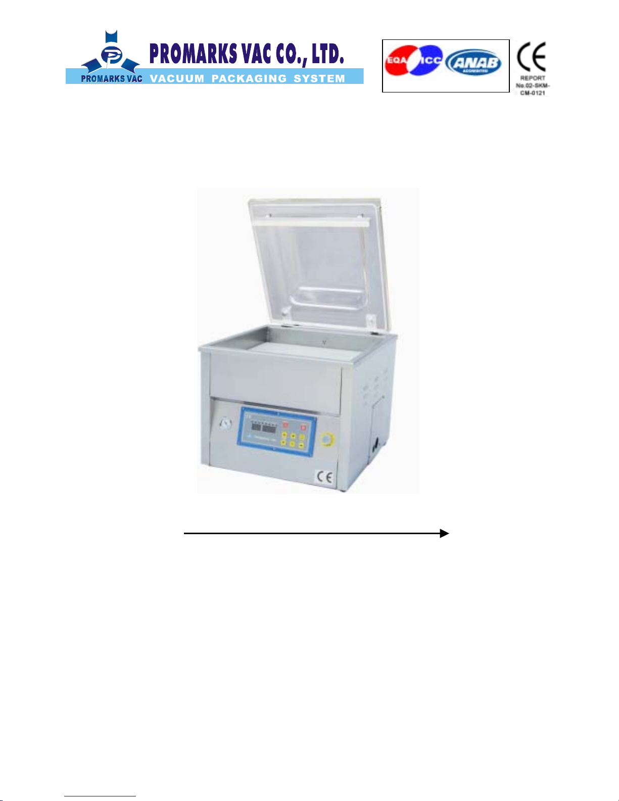
TC-420
Table Top Vacuum Packaging Machine
Operation Manual
PROMARKS INC U.S.A.
1599 Monte Vista Ave., Claremont CA91711 U.S.A
TEL:(909)482-1133
FAX:(909)482-1633
ISO 9001:2000

1
INDEX
SAFETY RECOMMENATIONS …………………………………………………………………..……. 3
1. Applications ……………………………………………………………………………………….……4
1.1 Why we need vacuum packaging ……………………………………………………………….4
1.2 Recommendation of vacuum pouch …………………………………………………………..… 4
2. Transportation instruction …………………………………………………………………………..…4
3. TC-420 Specification ………..……………..……………………………………..…… ……………...5
4. Installation………………………………………………………………………………………........ 5-6
4.1 Environment requirements ………………………………………………………………………. 5
4.2 Check oil level ……………………………………………………………………………………... 6
4.3 Plug-up power Cord …………………………………………………………………………….... 6
5. Operation …………………………………………………………………………………………...7-12
5.1 Option device …………………………………………………………………………………….... 7
5.1.1 Gas flushing unit …………………………………………………………………………….. 7
5.1.2 High pressure seal …………………………………………………………………………… 7
5.2 LED control panel function …….………………………………………………………….…8-12
5.2.1 PV-01 control panel ……………………………………………………………………..8-9
5.2.2 PV-02 control panel ……………………………………………………………………9-12
6. Maintenance ……………………………………………………………………………….……...13-15
6.1 Machine maintenance ………………………………………………………………………… ...13
6.2 Vacuum pump maintenance ………………………………………………………………….….13
6.3 Rebuilding sealing bar ………………………………………………………………………..13-14
6.4 Maintenance time and item chart …………………………………………………………….. 15
7. Trouble shooting …………………………………………………………………………………. 16-19
7.1 Problems and remedies …………………………………………………………………….. 16-17
7.2 Pneumatic diagram ……………………………………………………………….……………..18
7.3 Electrical diagram ……………………………………..………………………...…………... ….19
7.3.1 PV-01 standard ………..…….………………………………………………………..… 19
7.3.2 PV-02 standard………………………………………………………………………….. 19

2
8. Replacement parts ………………………………………………………………………………. 20-30
8.1 Lid diagram ……………………………………………………….………………………….. 21-22
8.2 Vacuum chamber diagram ………. ……………… ……………………………………… . 23-28
8.3 Body diagram ……………………………….…………………………………………..…… 29-30
8.4 Electrical box diagram ….. .…………….……………………………………………..……. 31-32
8.5 Electrical box diagram for gas .………………..……………………………………..…….. 33-34

3
SAFETY RECOMMENDATION
CERTAIN PRACTICES OR MINOR MODIFICATIONS ON THE PART OF THE USER MAY
INCREASE THE RISK OF DAMAGE AND/OR ACCIDENTS.
IN THE INTERESTS OF SAFE INSTALLATION, HANDLING AND MAINTENANCE, THE
FOLLOWING RECOMMENDATIONS SHOULD BE STRICTLY FOLLOWED:
1) Do not attempt to start or handle the machine until all safety topics, installation instructions,
operator’s guide and maintenance procedures have been fulfilled and understood.
2) All adjustments, repairs must only be carries out by qualified maintenance personnel,
according to the instructions in this manual.
3) The operator must never insert hands, rags, etc. inside the machine while it is functioning.
4) Do not place tools, parts or other objects on or inside the machine.
5) Always keep the machine clean, oiled and in good working condition.
6) To provide continued protection against risk of electrical shock. Connect to properly
grounded outlets only.
7) Always disconnect machine from power source (main power switch) as show on next page
before removing service panel.

4
1. APPLICATIONS
Frozen food, sea food, prepared food, meat, soaked foods, herbal medicine, tea leaves,
hardware parts and accessories, and electronic products … etc.
1.1 WHY WE NEED VACUUM PACKAGING
Maintaining food’s freshness and flavor; antiseptic, and mold resistant.
Extend storage period and shelf life for packed goods.
Prevents electronic and hardware parts from rusting and dampening.
1.2 RECOMMENDATION OF VACUUM POUCH
In order to get perfect result after vacuum and provide longer shelf life for vacuum packaging
that we recommend customer to use material of NY/LDPE.
2. TRANSPORTATION INSTRUCTION
For the transportation and placing of this machine have a forklift truck available (keep in mind
weight of the machine before lifting)
Precautions to take:
Before lifting balance the machine by adjusting the forks of the fork lift before lifting the
machine. Make sure the machine is safe to lift
Lift the machine with the forklift, from the front of the machine (opposite to the electrical
box). Check for components hanging under the machine before lifting because it may
cause machine to fall .
Always lift the machine by placing the forks of the truck between the two free casters of the
machine; never lift it by the ends or extensions.
Always take the utmost care when carrying out lifting and moving operations.
Approximate weight of the machine: 110kg or220lbs.
Before installation, remove the pallet under the machine then place the machine down for
installation.

5
3. TC-420 SPECIFICATION
4. INSTALLATION
4.1 Environmental requirement
Due to oil stiffening in cold working environment, the machine is hard to started if the air
temperature is very low. Machine, therefore, ought to be set up in:
Room with air temperature around 5~40oC.
Working elevation between 0~1000 meter.
Humidity between 30~95% RH.
There must be free access for air to vacuum pump for cooling, so it is normal situation
if the machine temperature keep in 70oC~80oC during operation.
For ventilation allow at least 20 cm space on each side of the machine.
6
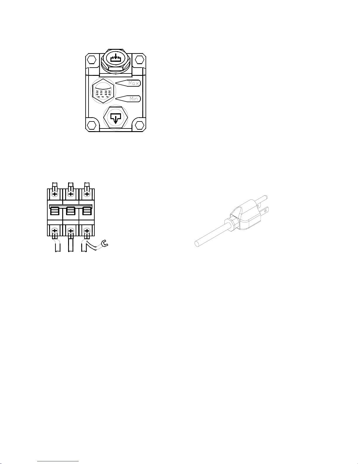
4.2 CHECK OIL LEVEL
Check oil level (see oil level in view glass) on vacuum pump, add if necessary.
4.3 PLUG-UP POWER CORD
Before plug-up the power cord make sure you have right power source to hook up the pump.
Please look at the back of the machine for the current requirement.
PE
OR

7
5. OPERATION:
Products Vacuum time/Sec
Storage life when
stored at 2~6oC/day
Fresh meat 30 10
Pork 30 10
Beef 30 30
Meat with liquid 15~30 14
Pasta 3~9 21
Sliced sausage 15 10
Cold cuts 9 10~21
Turn on the main switch and see LCD display showed operation menu on screen,
machine is now ready for operation.
Place bag on machine.( Please note the filler plates on the working table are for
decrease the volume of the chamber, speeding up evacuation. It will take longer vacuum
time if customer take out the plates.)
Close lid for automatic operating cycle, lid will open automatically when packaging cycle
is finished.
Remove sealed product from vacuum chamber.
The machine is again ready for operation.
After work finished please let vacuum pump running for about 15 minute and then turn off
the main switch to shut off the machine.
5.1 OPTION DEVICE
5.1.1 GAS FLUSHING UNIT
A variety of products must be treated with inert gas to give them a longer shelf life.
For this reason the machines can be equipped with a gas-flushing device.
To bring gas in package, pull the pouch over the gas flushing jet when you load it. (Be sure
that there are no wrinkles in pouch because it causes defective seals). Set LCD control
panel to “GAS” and set the gas flushing time about 3 seconds (the gas time must depend
on vacuum pouch size to make). Experiment to determine the best setting. The inert gas
can be drawn directly from gas tank thought a precision pressure-regulating valve. The
pressure should be approx. 3 bar.
The customer must supply a suitable regulator with a range of 0 to 42 p.s.i. We recommend
Using a food-grade flexible hose with a 1/4-inch I.D. and a maximum length of 15-ft.
Maximum regulator pressure is 42 p.s.i
5.1.2 HIGH PRESSURE SEAL (AIR ASSISTANCE)
If the pouch which you use is aluminum film or very thick film or the products must be
cooked in boiled water over 120oC, we suggest you equip with an additional sealing
pressure device to warrantee the sealing in good condition and not be pulled open easily.
NOTE: Please set air pressure between 1.0 ~ 1.5 kgs/cm2.
8
5.2 LED CONTROL PANEL FUNCTIONS
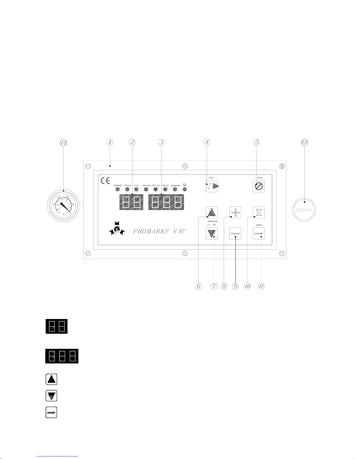
5.2.1 PV-01 control panel
○
1 Control panel ○
6 Program number up ○
10 Edit
○
2 Program number ○
7 Program number down ○
11 Shift / Save value
○
3 Function value ○
8 Increase value ○
12 Vacuum gauge
○
4 Skip to next function
○
5 Reset / Emergency stop
○
9 Decrease value ○
13 Power switch (On/Off)
● 1st display ○
2 : Indicates the program numbers.
● 2nd display ○
3 : Indicates the value of each functions.
● Program number up : Program number goes up by pressing this button.
●Program number down : Program number goes down by pressing this button.
●Shift : Shift to next function/selection and save the previous setting.
9
● Increase value : Increase any value by pressing this button.
● Decrease value : Decrease any value by pressing this button.
●Emergency stop : Stop current function and skip to ventilation.
●Stop vacuum : Stop vacuuming and skip to sealing.
Note: When “oil change” lamp lighting, please press “EMERGENCY STOP” button to clean
it.
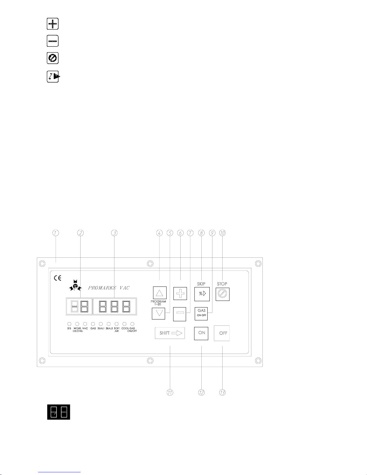
5.2.2 PV-02 control panel
○
1 Control panel ○
6 Increase value ○
11 Shift / Save value
○
2 Program number ○
7 Decrease value ○
12 Power switch (On)
○
3 Function value ○
8 Stop vacuum ○
13 Power switch (Off)
○
4 Program number up
○
5 Program number down
○
9 Gas On/ Off
○
10 Reset / Emergency stop
●1st display ○
2 : First display allows you to use up to 20 different programs as
require . You can store up to 20 programs with different value of vacuum, gas, sealing 1, sealing 2,

10
soft air, cooling time.
●2nd display ○
3 : Second function allows you to adjust time for each given
function of Vacuum, GAS, SEAL1, SEAL2, SOFTAIR, COOLING, and other required parameter
setting .
●Program number up ○
4 : Program number goes up by pressing button.
●Program number down ○
5 : Program number goes down by pressing button.
●Increase value ○
6 : Increase any value by pressing button.
●Decrease value ○
7 : Decrease any value by pressing button.
●Stop vacuum ○
8 : Stop vacuuming and skip to next function by pressing button.
●Gas On/Off ○
9 : Switch on or off of gas flushing device by pressing button.
●Emergency stop ○
10 : Ends current cycle in process and skip to ventilation.
●Shift button ○
11 Press hift and Select any function of vacuum, gas, sealing1, sealing2,
soft air, cooling and save the previous setting.
●○
12 : Turn on the power of control panel by pressing button.
Note: You must press ON the power of control panel after turning the main power o
●○
13 Turn off the power of control panel by pressing switch
Description of each function:
Vac.: To adjust the vacuum time first press shift button to VAC then press or to adjust
the desire vacuum, after adjusting press Shift again to save the value.
Note: The vacuum value can be controlled byA. time B. vacuum % plus time delay.(see
description of parameter section)
A. If the number shows “99” means vacuum time by 99 sec.
B. If the number shows”-99” means vacuum by 99 %. After “-99” you can obtain extra
vacuum time to delay by press button.

11
Gas (optional): To adjust the gas time first press shift button to GAS then press or to
adjust the desire gas time after adjusting press Shift again to save the value
How to bring the gas into the package: Pull the pouch over the gas nozzle. (Be sure that there
are not wrinkles in pouch because it causes defective seals). Set the gas value by percentage
(the gas pressure will depend on vacuum pouch size). Adjust the gas regulator valve to the
amount of gas required to insert in the bag The pressure of tank should be approx. 3 bar.
Note: The gas function only design for customer who has gas flushing system. If your
machine is not equip with gas flushing system please switch off gas function and timed
gas value to be “0”.
Sealing 1 :: To adjust the Seal time first press shift button toSEAL1 then press or to
adjust the desire seal time after adjusting press Shift again to save the value
Note: The best sealing time is around 2~4 sec, it is depends on the thickness of the
vacuum pouch. The value of sealing is equal to the sealing temperature. Too low or
too high the value will make the vacuum pouch be pulled part very easily by hand or
there will be a burnt mark appearance.
Do not adjust the sealing time more then 4 seconds. If you could not achive the desire seal
temperature please contact your local distributor or the manufacturer of this equipment.
※
Sealing 2 :Optional: If your machine equip with different length of seal bar like L type seal
bar. You can have separate sealing time control for each seal bar to obtain best seal
quality.
Note: Sealing 2 is design for customer who has different length of sealing bar. If the
machine has the same sealing bar then, please timed the same sealing time for sealing
1 and sealing 2 to obtain best seal quality.
Please follow the same procedure of SEALING1 to adjust the sealing time for SEALING2.
Soft air (optional): To adjust the Soft AIr time first press shift button to SOFTAIR then press
or to adjust the desire soft air time after adjusting press Shift again to save the value
Cooling :: To adjust the Cooling time first press shift button to COOLING then press or
to adjust the desire cooling time after adjusting press Shift again to save the value
machine have not equip with gas flushing device please switch off gas function and timed
gas value to be “0”.

12
Sealing 1 : You can increase or decrease sealing value by pressing or button
with Sealing 1 lamp lighting(The sealing time is from 0.1 to 10 Sec). After setting the
best value, to press SHIFT button for saving value and move it to next function.
Note: The best sealing time is around 2~4 sec, it is depends on the thickness of the
vacuum pouch. The value of sealing is equal to the sealing temperature. Too low or
too high the value will make the vacuum pouch be pulled apart very easily by hand or
there will be a burnt mark appearance.
Sealing 2 : If your machine equip with different length of seal bar like L type seal bar. You
can have separate sealing time control for each seal bar to obtain best seal quality.
Note: Sealing 2 is design for customer who has different length of sealing bar. If the
machine has the same sealing bar then, please timed the same sealing time for sealing
1 and sealing 2 to obtain best seal quality.
Soft air (optional): You can increase or decrease soft air time by pressing or
button with Soft air lamp lighting(The soft air time is from 0.1 to 10 Sec). After setting the
best value, press SHIFT button for saving value and move it to next function.
Cooling : You can increase or decrease Cooling time by pressing or button with
Cooling lamp lighting(The Cooling time is from 0.1 to 10 Sec). After setting the best
value, press SHIFT button for saving value and move it to next function.
13
6. MAINTENANCE
6.1 DAILY MACHINE CLEANING
The TC-420 double chamber vacuum packaging machine should be cleaned every day. Use
special care to clean seal bar and seal back-up strip. We recommend cleaning by hand with a
mild detergent. Do not directly hose down machine.
6.2 VACUUM PUMP MAINTENANCE
Consult pump operation manual (provided with the machine).
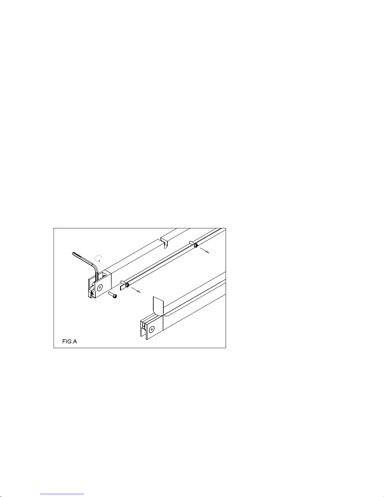
6.3 REBUILDING SEALING BAR
Remove seal bar units from vacuum lid.
Loosen round head screw from the side of the sealing bar and take the stainless steel
clamp off.
Pull off Teflon tape strip and discard. Using a normal hex key wrenches, loosen the
screw at each end of sealing bar.
The sealing wire can now be removed and discarded. Clean the Teflon tape adhesive
from the bars using an acetone cleaner or equivalent. (Fig.A)

14
If you are only replacing the sealing wire and Teflon tape, check the spring retainer.
The spring must be filled into the end side of the sealing bar otherwise the sealing wire
will be easily broken during heat deliver. (FIG.B)
FIG.B
SET SCREW
Feed new sealing wire through one of seal bar and secure, leaving about 3/4” (20mm) of
excess, thread element through opposite end and leave clamping screw loose. Using
tool provided or needle nose pliers, stretch element tight as shown. Secure clamping
screw and check tension by pulling up the element at the middle of the bar, maximum
pull should not exceed 3/16” (5mm). If there is not enough tension, retighten as
necessary. (FIG.C)
NOTE: Elements will break in the middle of the bar if not enough tension is set.
Install the new Teflon tape strip to the bar. Remember to change Teflon tape are regular
intervals to ensure proper sealing surface.
3
1
FIG.C
3

15
6.4 MAINTENANCE TIME AND ITEM CHART
Maintenance time
and item Daily Every
two
months
Every
four
months Yearly Every
two
years
Three
to five
years
Footnotes
space
Let vacuum pump
running for about 15
minutes with vacuum
lid open after work
finished X
Check the oil level X
Check the sound of
motor X
Oil come out from
exhaust cover or not X
Bottom sealing bar
working normally or
not X
Clean exhaust filter X
Change vacuum oil X
Replace exhaust filter X
Replace teflon tape X
A
s request
Replace sealing
silicone rubber X
A
s request
Replace lid gasket
rubber X
A
s request
Replace pressure bag X
A
s request
Replace vanes X
Above mentioned maintenance time are base on 8 working hour per day.
Recommend oil : Grav. API 30.5
Pour Pt. -15℃
Flash Pt. 225℃
Viscosity 32.05 CST@40℃
Color Light Yellow
V.I. 100

16
7. TROUBLE SHOOTING
7.1 Possible problems and remedies are identified as below:
Problem Possible cause Possible remedy
Control panel is under normal
function, but vacuum pump
will not start.
The KM1,QM1, MCB1, MCB2
protector are disconnect. Check each parts and turn
on the switch.
Vacuum pump does not run. The power requirement is not
match those given on nameplate.
Change power source.
Insufficient vacuum in
chamber.
Low oil level in vacuum pump.
Vacuum pump is rotating in
wrong direction.
Lid silicone rubber damage.
Vacuum valve does not open.
Add oil if necessary.
Re-polarize motor.
Replace.
Clean membrane rubber.
Insufficient vacuum in bag.
Note: Most frequently
insufficient vacuum in bag is
due to leakage in bag not
fault in machine.
Bag is leaking.
Sharp corners penetrate bag.
Bag is too large.
Change bag.
Change bag.
Use thicker bag.
Vacuum pouch is easily
pulled apart by hand. Sealing time (temperature) is
too short(low).
Adjusting.
Sealing area has some burnt
mark or bubbles appearance. Sealing area jam with oil or meat
juice.
Sealing time (temperature) is
too long(high).
Clean it.
Lid does not open Vacuum valve broken
Replace

17
Problem Possible cause Possible remedy
None or bad sealing.
Note: Please do not adjust
sealing time longer than
regular time, it will
reduce the life of Teflon tape
and silicone rubber.
Sealing wire is broken.
Sealing wire is loosen.
Insufficient pressure.
Sealing transformer defective.
Teflon tape or silicone rubber
is damage.
Sealing time and cooling time
is too short.
Sealing pressure is too low.
Replace.
Tighten up a sealing wire.
Pressure bar defective:
replace.
Replace.
Replace.
Adjust to proper sealing
time.
Replace bladder bag.
Lid does not close. Vacuum valve broken
Limit switch disconnection
Replace
Adjusting
18
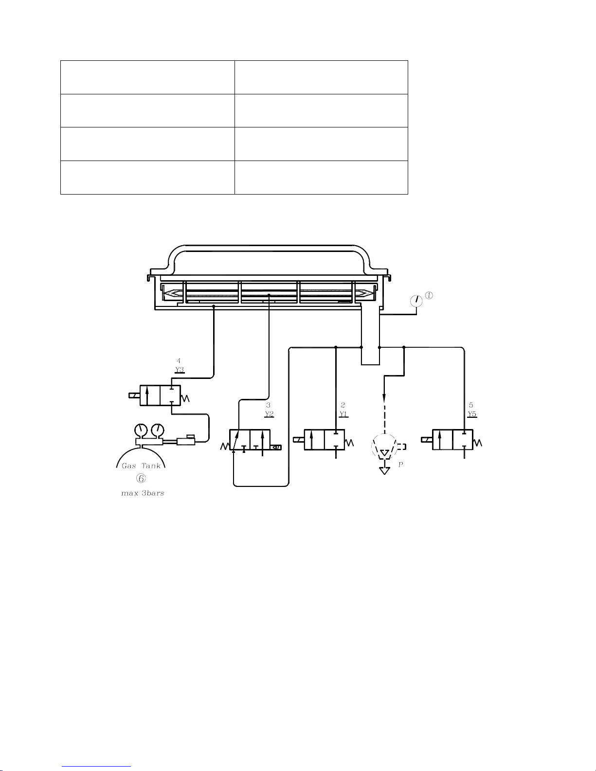
7.2 PNEUMATIC DIAGRAM
○
1 Vacuum Gauge ○
5 Y5 : Soft Air Valve
○
2 Y1: Ventilation Valve ○
6 Gas Tank
○
3 Y2: Sealing Valve P. Vacuum Pump
○
4 Y3 : Gas Valve
A
R P
AA A
19
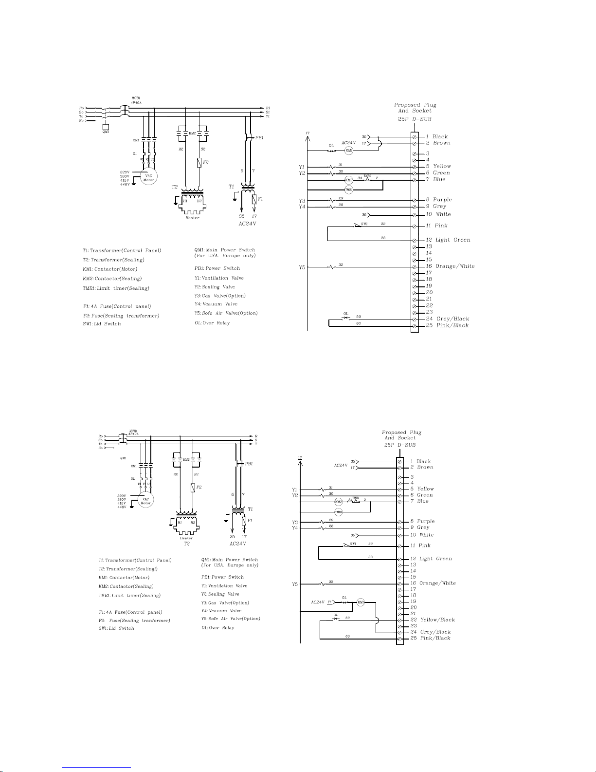
7.3 Electrical diagram
7.3.1PV-01standard
7.3.2 PV-02 standard
Table of contents
Other PROMARKS Food Saver manuals


