PROMARKS TM-1500 User manual

TM-1500
Vacuum Tumbling Machine
Operation Manual
PROMARKS INC U.S.A.
1599 Monte Vista Ave., Claremont CA 91711 U.S.A
TEL:(909)482-1133
FAX:(909)482-1633
ISO 9001:2000

1
INDEX
1. Installation ………………………………………………………………………………2
2. Maintenance …………………………………………………………………… ………2
3. Functions and operations …………………………………………………… ………2
4. Control panel …………………………………………………………………… ……3-4
5. Machine diagram ……………………………………………………………… ………5
6. Electrical diagram …………………………………………………………… ………6
7. Machine operation explain………………………………………………………………7
8. Typical vacuum control settings…………………………………………………………8
9. Replacement parts……………………………………………………………………9-15
8.1 Drum body diagram………………………………………………………………10-11
8.2 Machine case diagram ……………………………………………………12-13
8.3 Control box diagram …………………………………………………………… 14-15

2
1. INSTALLATION.
Please check the electric power listed on the vacuum pump and install the vacuum pump correctly,
ground line must on the floor.
2. MAINTENANCE.
A. To ensure vacuum pump works smoothly suggest change the vacuum oil every 500 working
hours or every a half year.
B. Check water filter bottle everyday, as soon as the water over a half of the bottle please cleans it.
3. FUNCTIONS AND OPERATIONS.
○
1 LED control panel
○
2 Inverter
○
3 Mixing motor ON/OFF Switch
○
4 Vacuum pump ON/OFF Switch
○
5 Vacuum Gauge
○
6 Main power switch
Cleaning. The tumbler inside must be cleaned everyday after working hours.
3
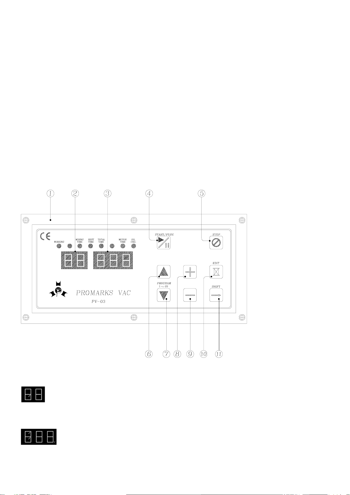
4.CONTROL PANEL.
PV-03 CONTROL PANEL
○
1 Control panel ○
6 Program number up ○
10 Edit
○
2 Program number ○
7 Program number down ○
11 Shift / Save value
○
3 Function value ○
8 Increase value
○
4 Start/Pause
○
5 Stop
○
9 Decrease value
● 1st display ○
2 : First display allows you to use up to 20 different programs as require . You can store up
to 20 programs with different value of mining, rest, total time.
● 2nd display ○
3 : Second function allows you to adjust time for each given function of mining, rest,
total time, and other required parameter setting .
4
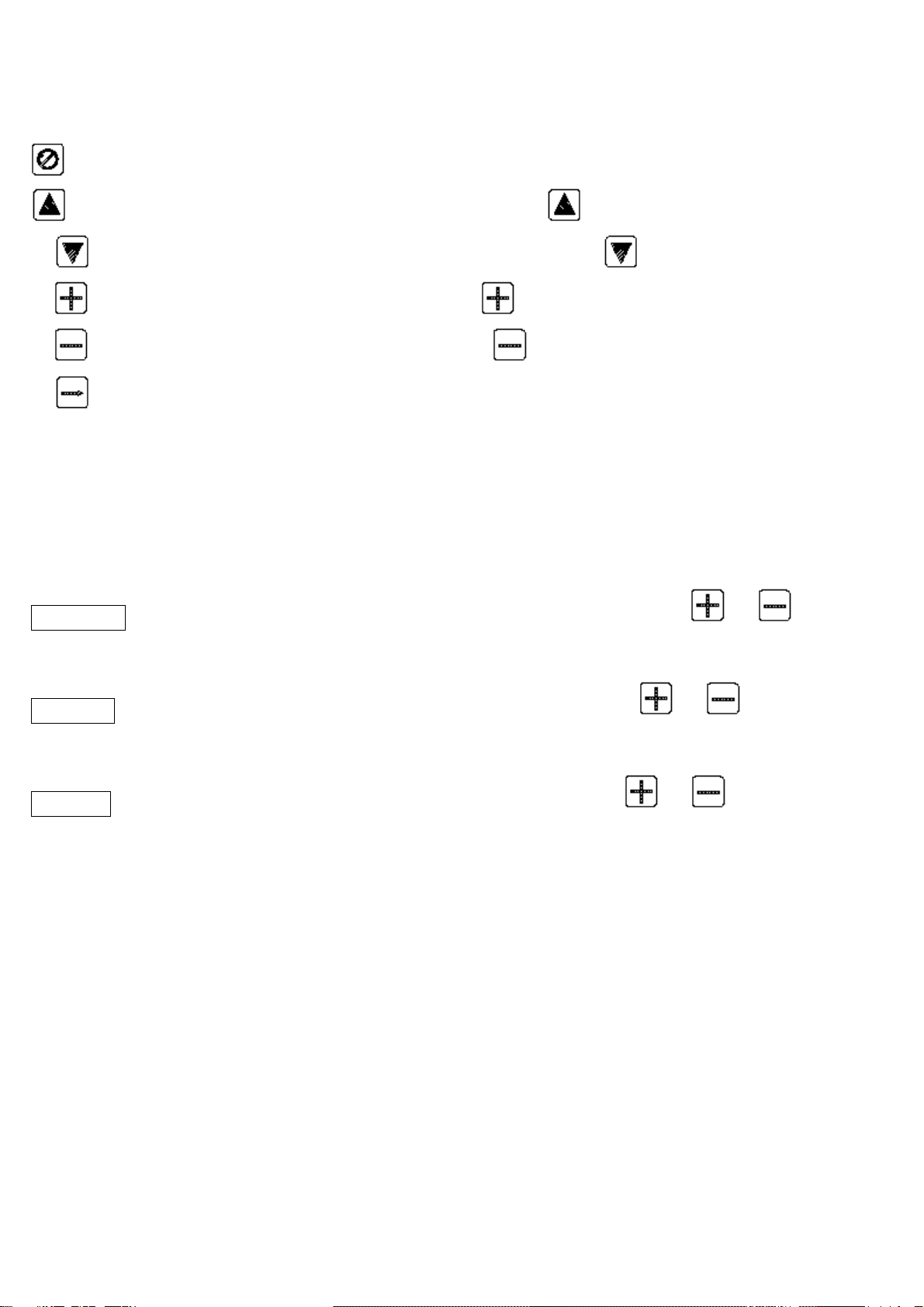
● Start/Pause○
4 : To start / pause machine function by pressing Start / Pause button.
Stop ○
5 : Ends current cycle in process and skip to ventilation.
Program number up ○
6 : Program number goes up by pressing button.
● Program number down○
7 : Program number goes down by pressing button.
● Increase value ○
8 : Increase any value by pressing button.
● Decrease value ○
9 : Decrease any value by pressing button.
● Shift ○
11 : Shift to next function/selection and save the previous setting.
●Note: When “oil change” lamp lighting, please press “STOP” button to clean it.
Description of each function:
Mixing Time.: To adjust the Mixing Time first press shift button to Mixing Time then press or to adjust the
desire time, after adjusting press Shift again to save the value.
Rest Time :: To adjust the Rest time first press shift button to Rest Time then press or to adjust the desire
Rest Time after adjusting press Shift again to save the value
Total Time : To adjust the total time first press shift button to total time then press or to adjust the desire
total time after adjusting press shift again to save the value
Parameter Setting : Important before changing any given function below please follow parameter setting A
before entering and after setting press SHIFT then follow setting B after every function.
A. To enter parameter setting press EDIT & SHIFT button for 3 sec until get in parameter.
B. To exit from parameter setting to normal function press SKIP button for 3 sec
5
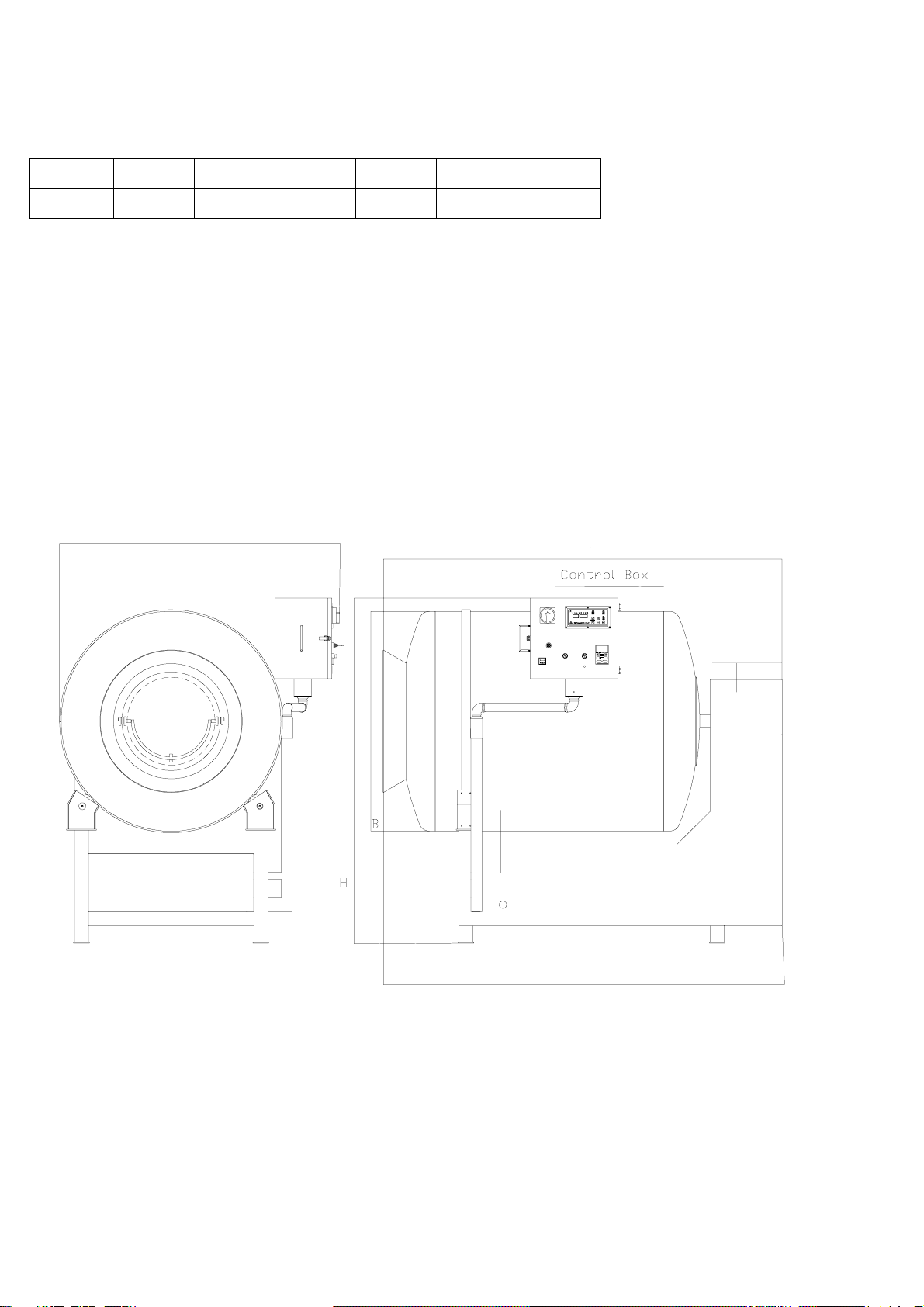
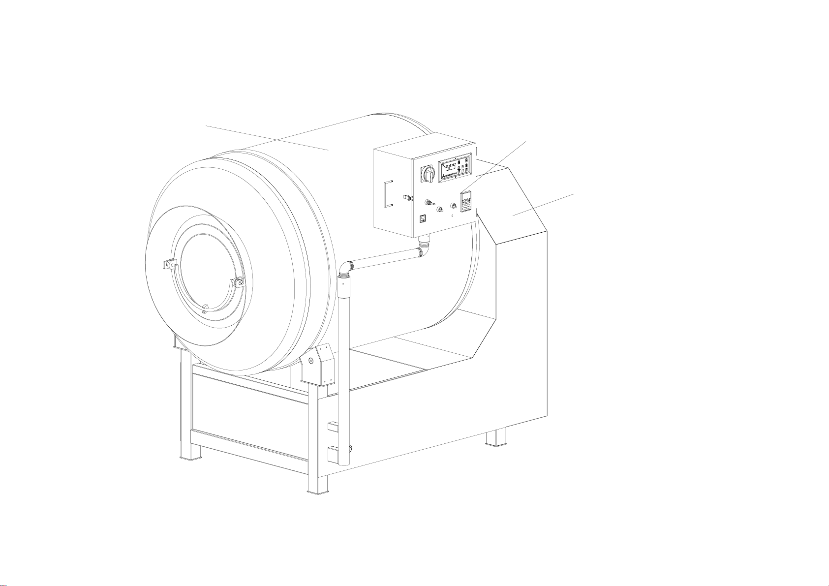
5.MACHINE DIAGRAM
Model W L H A B Capacity
TM-1500 1900 1565 2280 1700 Φ1250 700Kg
Drum Body
Machine Case
A
L
W
Vacuum Cover
6
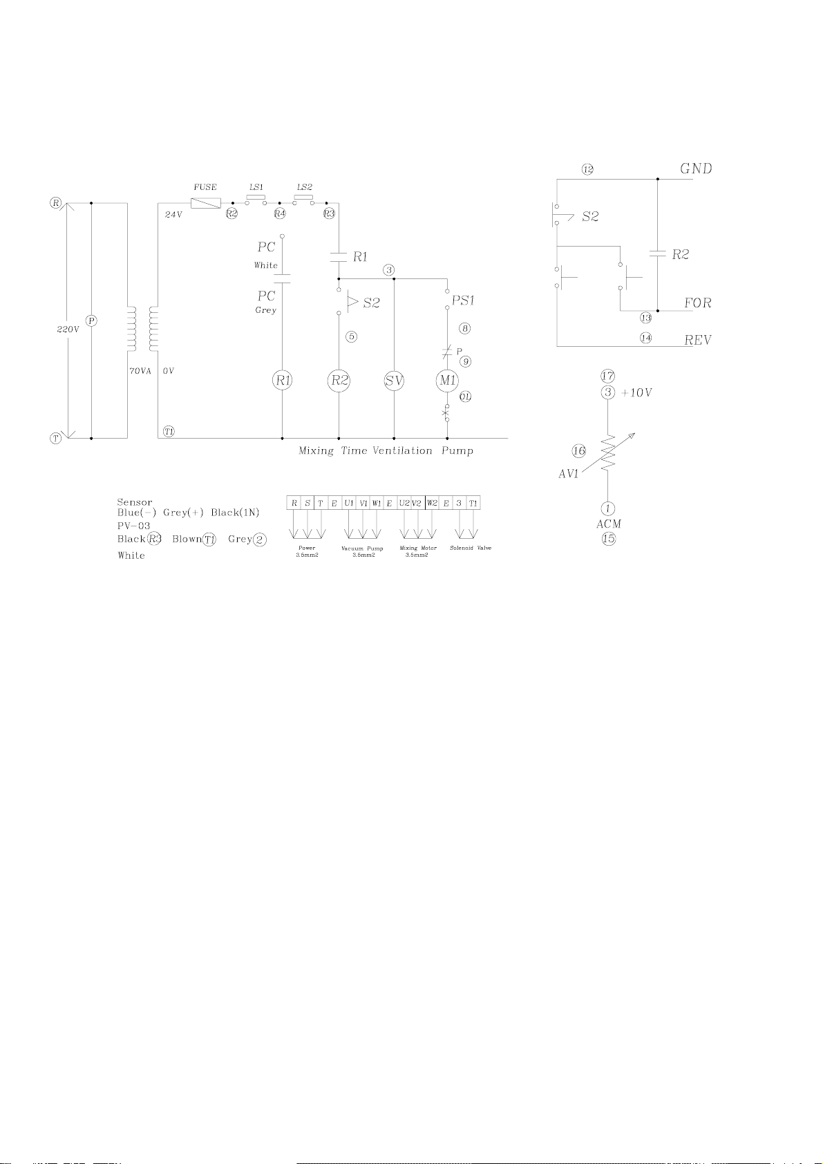
6.ELECTRICAL DIAGRAM.

7
7.MACHINE OPERATION EXPLAIN.
Check the right power source with the name plate of the machine. Plug in the power and ready to operate the machine.
Turn on main power switch and set the value on control panel. After finish all of the setting push down the safety bar
and press “Start/Pause” button to start the function. Safety function will be effective and machine will stop at the
same time while user pull up the safety bar or gear motor box during working process.
After vacuum tumbling job finish, machine will stop and air ventilation at the same time. As soon as machine finish air
ventilation, open the vacuum cover and use unloading switch to unload the product in drum.
The stopper on the side of the machine is design to hold the drum and remain it in the same angle and help user to load in
the processing product.
How to use the stopper: A. Push in the handle bar of stopper to the hole of the drum before load in the processing
product.
B. Pull back the handle bar of stopper from the hole of the drum before start the machine.
Warning: The handle bar of the stopper must be pulled back before user start the machine!! The machine will be
damaged if user have not fulfill it!!

8
8. Typical vacuum control settings.
PRODUCTS % OF
VACUUM
CTRL SPEED
SETTING RPM TUMBLING TIME
Boneless chicken breast 95% 10 1/2 15 min
Boneless pork chops 95% 10 1/2 15 min
Rufy fillet 95% 7 1/2 12~24 min
Whitefish fillet 95% 6 1/2
on 5 off 5 on 5 done
Peeled & divined shrimp 95% 6 1/2 12~24 min
Turkey drum 95% 14 45 min to 2 hours
Ribs 95% 12 45 min
Beef Shish 95% 7 1/2 15 min
Chicken shish 95% 7 1/2 15 min
Sirloin steak - 1" cut 95% 7 1/2 12~15 min
Delmonico steak - 1" cut 95% 7 1/2 12~15 min
Strip steak - 1" cut 95% 7 1/2 12~15 min
Cuck steak - 1" cut 95% 9 15 min
Round steak - 1" cut 95% 10 1/2 15~20 min
Teriyaki tip 95% 9 15 min
Adjust accordingly for thickness and lap length
With mock tender and salse strap fat removed
Always keep 60% real capacity of total capacity(same as model NO.)
We recommend customer to use injector before vacuum tumbling if meat size
is very thick(whole chicken…etc.)
9
Drum Body
Machine Case
Control Box
Vacuum Tumbling Machine
10

11
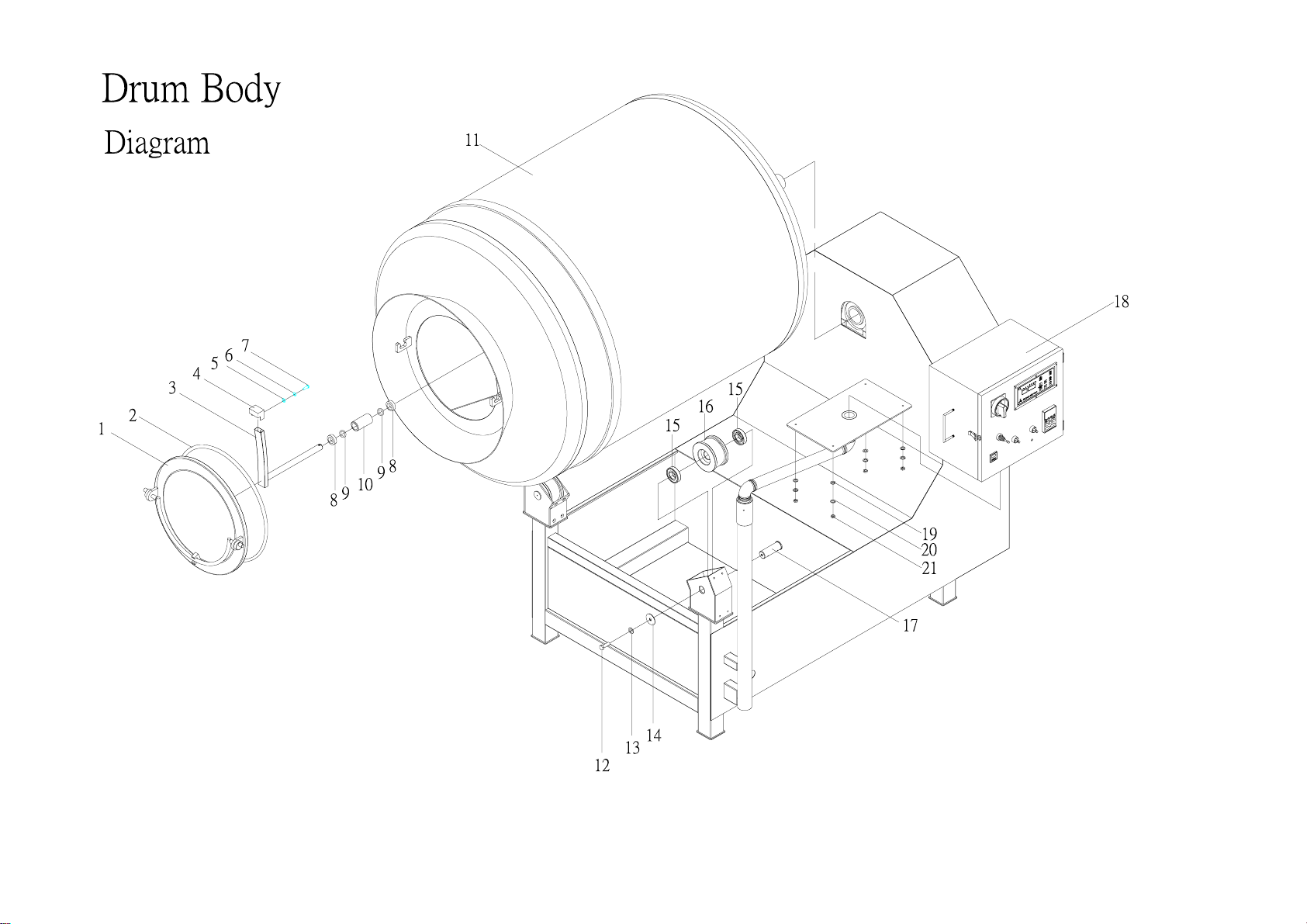
Drum Body
Part List
Pos Name Quantity Parts No Note
1 Vacuum lid 1 SD100224010D
2 Lid gasket 1 PA0410200100
3 Nozzle 1 SD100228010D
4 Nozzle cap 1 SD100201010E
5 Spring washer 1 NA0806000001
6 Washer 1 NA0706000001
7 Screw 1 NA0406001501 Hex head
8 Oil sealer 2 BA0503020080
9 Retaining ring 2 QA2223191010
10 Socket 1 PD300012010D
11 Drum body 1 SD100217010D
12 Screw 1 NA0406002501 Hex head
13 Washer 1 NA0706000001
14 Axle slice 2 SD200063010D
15 Bearing 2 BA0903507217
16 Gear 2 SD200056050D
17 Axle center 1 RA200005010D
18 Electrical box 1 SD400124010E
19 Spring washer 4 NA0806000001
20 Washer 4 NA0706000001
21 Screw 4 NA0406002501 Hex head
12

13
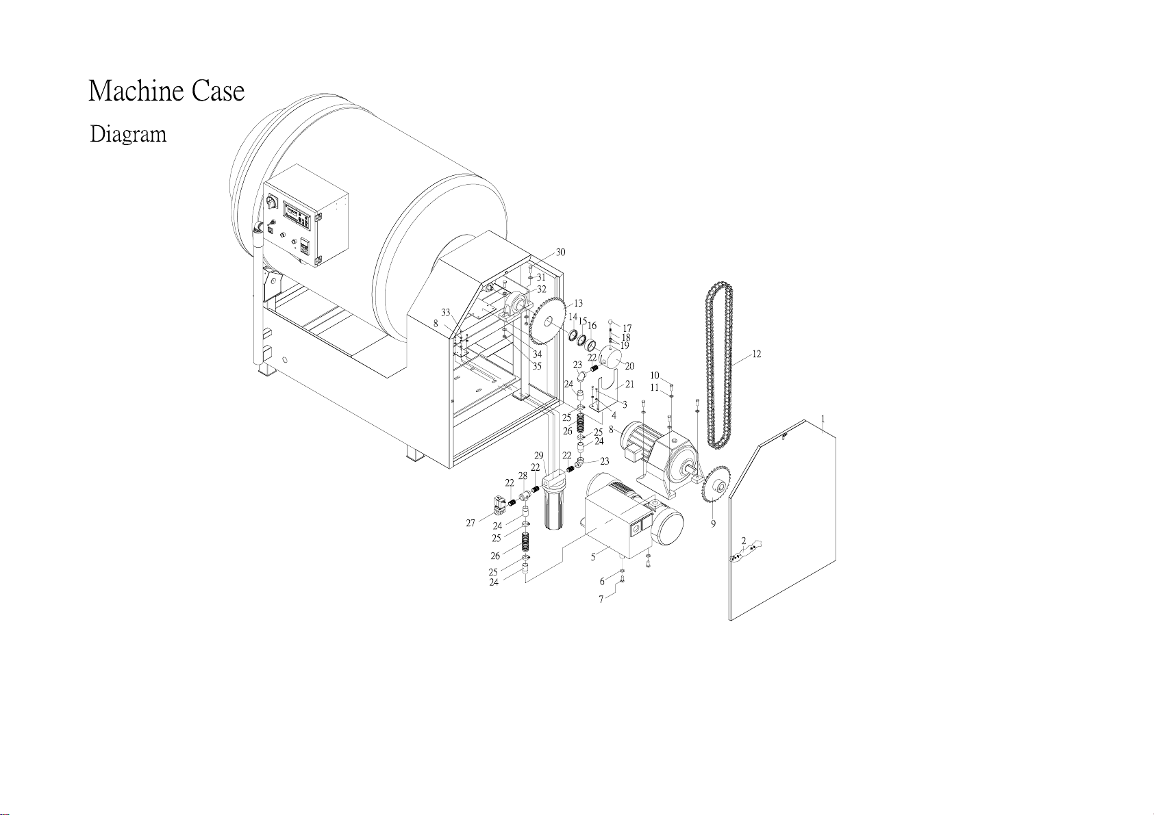
Machine Case
Part List
Pos Name Quantity Parts No Note Pos Name Quantity Parts No Note
1 Machine Case SD300232010E 1 22 Nipple CA0208005022 1
2 Locker QA3100401010 1 23 Femal tee connector CA0408008010 1
3 Washer NA0720000001 2 24 Nipple CA0208015020 3
4 Screw nut NA1020000001 2 25 Pipe clamp QA1118323100 4
5 Vacuum pump TA0001433100 1 26 Vacuum hose PA0602540330 2
6 Washer NA0708000001 3 27 Solenoid valve EA0310405070 1
7 Screw NA0408001201 3 Hex head 28 Femal tee connector CA04080080101
8 Washer NA0705000001 4 29 Water filter QA0801010001 1
9 Gear MD300016060D 1 30 Screw NA0420015001 2 Hex head
10 Screw NA0410003501 4 Hex head 31 Washer NA0720000001 2
11 Washer NA0710000001 8 32 Bearing BA1007007300 1
12 Chain QA0605002800 1 33 Screw NA0405002001 4 Hex head
13 Gear MD300015060D 1
14 Oil seal BA0504535080 1
15 Oil seal BA0504535080 1
16 Socket AD100001250D 1
17 Handle LB2010000000 1
18 Pin RD100004281D 1
19 Oil seal BA0501808071 2
20 Air sucking set AD100003090D 1
21 Socket place SD201010060D 1
14

15
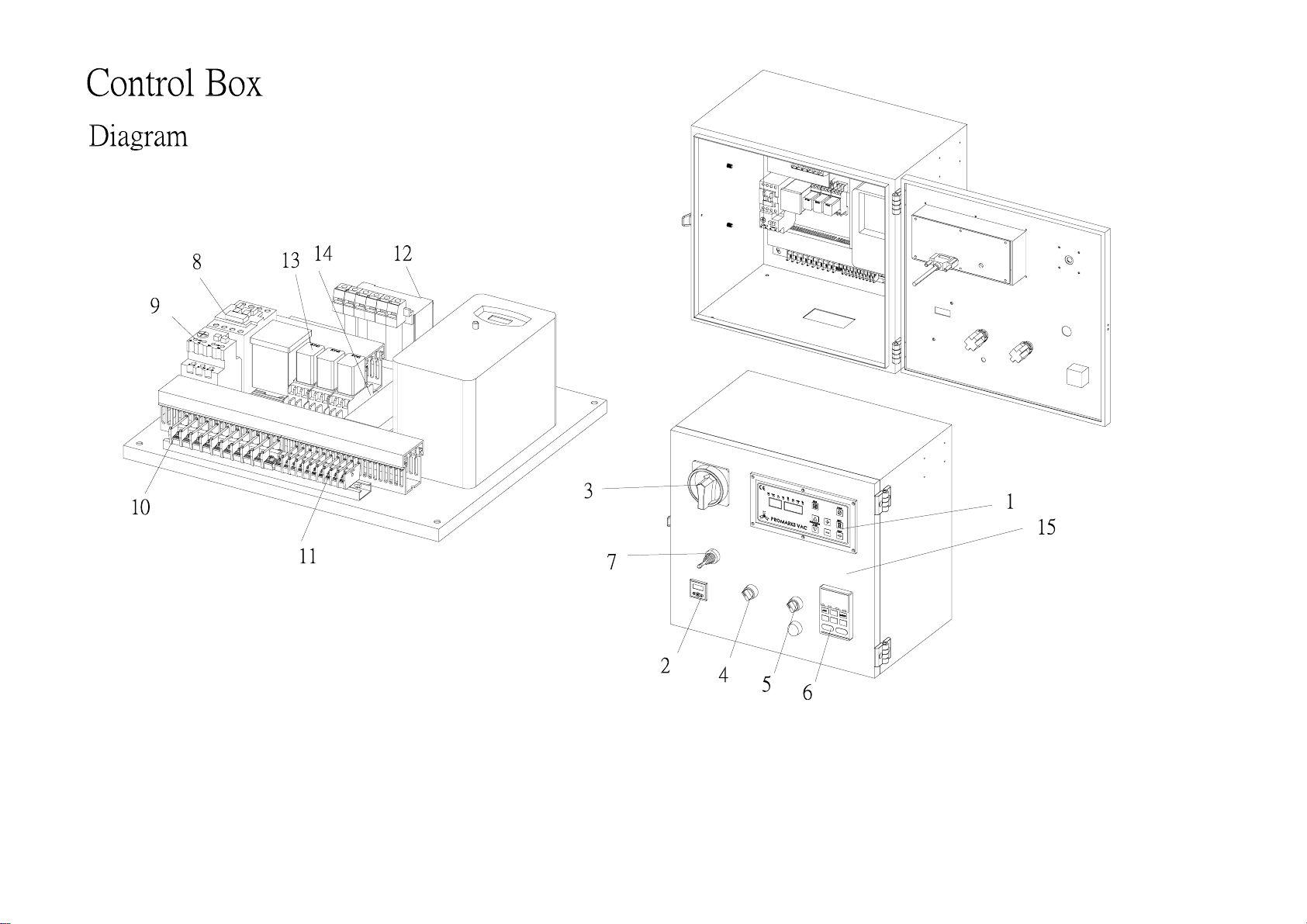
Control Box
Part List
Pos Name Quantity Parts No Note
1 Control panel 1 HA1303020300
2 Sensor switch 1 EA3621000000
3 Main power switch 1 HA2502020000
4 Select switch 1 EA2202200200
5 Select switch 1 EA2202200200
6 Invertor 1 EA5203022011 Vacuum pump
7 Joystick 1 EB1303010000
8 Contactor 1 EA1602125200 Motor
9 Overload relay 1 EA1702030000
10 Ground block 12 EA5603100000
11 Ground block 10 EA5603100010
12 Transformer 1 EA1504761011
13 Relay 3 EA4810024031
14 Relay holder 3 EA4902000000
15 Control box front door 1 SD400123010E
Table of contents
Other PROMARKS Kitchen Appliance manuals


