promesstec UDA 50-U Series User manual

Device features:
•red display from -1999...9999 digits (optional: green, orange oder blue)
•digit height 10 mm
•display adjustment via factory settings or directly at the sensor signal possible
•min/max memory
•5 parameterizable support points
•display flashes when limit value is exceeded / limit value undershot
•tara-function
•sliding averaging
•two semiconductor switching points galvanically not separated
•programming lock via code entry
•protection class IP65 front side
•pluggable screw clamp
•accessories: PC-based configuration software with CD and USB adapter
user manual UDA 50-…-U
promesstec GmbH
Niedersachsenstraße 4
D –48465 Schüttorf
Fon: +49 (0)25923 / 90229-0
Fax: +49 (0)25923 / 90229-29
www.promesstec.com
version 2.1.1UDA 50-…U…promesstec GmbH

Identification
STANDARD-TYPE ORDER NUMBER
UDA 50-5-U-0 99-003648
Dimension symbols are to be specified on request when ordering, e.g. mbar

Content
1. Short description 1
2. Assembly 2
3. Elektrical connection and connection examples 3
3.1. Pin assignment 3
3.2. Connection examples 3
3.2.1. Voltage / Current 3
3.2.2. Pt100 / Pt1000 / thermocouple 6
3.2.3. Frequency / Rotational speed 7
3.2.4. Counter 10
3.3. Switching points 11
connection examples
4. Functional description and operation 13
4.1. Operation and display elements 13
4.2. Programming software PM-TOOL 14
5. Setting the display 14
5.1.Switch on
6. Parameterization 15
6.1. Selection of the input signal, Type 15
6.1.1. Voltage / Current, Volt, AMPE 16
Setting the end and start value, End, Enda, offs, offa 17
Setting the decimal point, Dot.A 17
Zero point calming of the input signal,zero 17
Tare value, tara 17
Over/underflow behavior,over 17
Input of support points for linearization of the measurement signal,spc.A 18
6.1.2. Pt100, Pt1000, thermocouple, pt.se, ther 19
Temperature display in °C/°F,unit 19
Line adaptation,offs 19
6.1.3. Impulse measurement, impu 20
6.1.3.1. Frequency, freq 20
Impuls actuation,i.typ 21
Frequency range,rang 21
Filter,filt 22
Setting the end and start value,end,endf,offs,offf 22
Setting the decimal point, dot.F 22
Tare value,tara 22
Input of support points for linearization of the measurement signal, spc.F 22
6.1.3.2. Rotational speed, turn 23
Impuls actuation, i.typ 23
Filter,filt 24
Impuls per revolution,ppt 24
Time base,time 24
Setting the decimal point,dot 24

Content 6.1.3.3. Up/down counter, Co.up, Co.dn 25
Impuls actuation, i.typ 25
Counter base / impuls signal,co.ba 26
Flank, edge 26
Prescale,pres 26
Display end value and impulse count end value, end,end.c 26
6.2. General display parameters 27
Setting the measuring time, sec 27
Setting the floating average, glm 27
Start/end value representation in the display,di.hi,di.lo 27
Assigning functions to the direction keys,tast 27
Display flashes when limit value is undershot/exceeded, flas 27
6.3. Alarm parameters 28
Limit value behavior, a1.fu, a2.fu 29
Message in case of limit value error, a1.er, A2.er 29
Switching behavior of the outputs, a1.ty, A2.ty 29
Setting the switching threshold, a1.li,a2.li 29
Setting the hysteresis, a1.hy, a2.hy 29
Upper limit, a1.lo, a2.lo 30
Lower limit, a1.hi, a2.hi 30
Dropout delay, a1.of, a2.of 30
Pick-up delay, a1.on, a2.on 30
6.4. Backup parameter for locking the parameterization 30
Assignment of an individual numerical code, Code 30
Activation/deactivation of the programming lock, run 30
7. Reset to default values 30
Resetting the parameters to the delivery state
8. Technical data 31
9. Safety instructions 34
10. Troubleshooting 35

1
1. Short description
1. Short description
The switch panel meter UDA 50...-U... is a 4-digit digital display for measuring various measuring
signals such as voltage/current, temperature and frequency. The configuration is done via 3 front
keys or by means of an optional PC software PM-TOOL. An integrated programming lock
prevents unwanted changes to parameters and can be unlocked again via an individual code.
With the 2 integrated semiconductor switching points, limit values can be monitored and reported
to a higher-level control room. The electrical connection is made at the rear via plug-in clamps.
Selectable functions such as min/max value query, tare function, averaging, direct limit value
adjustment in operating mode and additional measuring support points for linearization of the
measuring input meet the requirements of measurement and control technology.

2. Assembly
2
2. Assembly
Please read the safety instructions on page 34 before assembly and keep these instructions for
future reference.
1. After removing the fasteners, insert the device.
2. Check seal for good fit.
3. Re-engage fastening elements and tighten clamping screws by hand. Then tighten further by
half a turn with the screwdriver..
ATTENTION! Torque should not exceed max. 0.1 Nm!

3. Electrical connection
3
3. Electrical connection
3.2. Connection examples
In the following you will find some connection examples in which practical applications are
shown:
3.2.1. Current / Voltage
2-wire sensor 4-20 mA
3.1. Pin assignment
Type UDA 50...-U... - Supply 9-28 VDC, galvanically not isolated
Note:
Clamps 3, 5 and 7 are
electrically connected in the
device.
+
9-28 VDC
1 VA
<
_
10V,PNP(HTL)
GND,Pt100(0)
50mV,TC,Pt100,Reset
1V,2V,mA,Frequenz,Pt100(0)
9 8 7 6 5 4 3 2 1
_
Signaleingänge Spannungs-
versorgung Halbleiter-
ausgänge
Schaltpunkt1
Schaltpunkt2
GND
Schaltpunkte
4-20 mA
_ +
9-28 VDC
9 8 7 6 5 4 3 2 1
Signal
GND S2 S1

4
3. Electrical connection
2-wire sensor 4-20 mA with external power supply
3-wire sensor 0/4-20 mA
3-wire sensor 0/4-20 mA with external power supply
Schaltpunkte
0/4-20 mA
_ +
9-28 VDC
9 8 7 6 5 4 3 2 1
Signal
GND S2 S1
_
+
0/4-20 mA
_
+
Transmitter-
versorgung
Schaltpunkte
9 8 7 6 5 4 3 2 1
GND S2 S1
_ +
9-28 VDC
Signal
Schaltpunkte
9 8 7 6 5 4 3 2 1
GND S2 S1
_ +
9-28 VDC0/4-20 mA
_
+
Transmitter-
versorgung
Signal

5
3. Electrical connection
3-wire sensor 0-1/2…10 V
3-wire sensor 0-1/2…10 V with external power supply
4-wire sensor 0-1/2…10 V, 50 mV
4-wire sensor 0-1/2…10 V, 50 mV with external power supply
Schaltpunkte
0-1/2...10 V
_ +
9-28 VDC
9 8 7 6 5 4 3 2 1
Signal
GND S2 S1
_
+
10 V1/2 V
Schaltpunkte
0-1/2...10 V, 50 mV
_ +
9-28 VDC
9 8 7 6 5 4 3 2 1
Signal
GND S2 S1
_
+
10V
1/2V 50mV
0-1/2...10 V
_
Transmitter-
versorgung
Schaltpunkte
9 8 7 6 5 4 3 2 1
GND S2 S1
_ +
9-28 VDC
Signal
1/2 V 10 V
_
+
0-1/2...10 V,
50 mV Transmitter-
versorgung
Schaltpunkte
9 8 7 6 5 4 3 2 1
GND S2 S1
_ +
9-28 VDC
Signal
1/2 V 10 V
50 mV
_
_
+
6
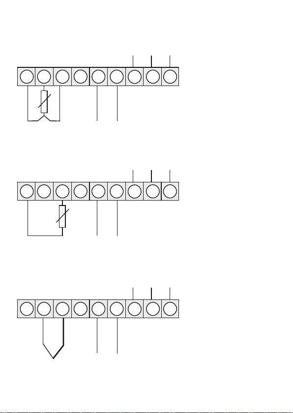
3. Electrical connection
Pt100 3-wire
Pt1000 2-wire
3.2.2. Temperature
Thermocouple
Schaltpunkte
9 8 7 6 5 4 3 2 1
GND S2 S1
_ +
9-28 VDC
Pt100
Schaltpunkte
9 8 7 6 5 4 3 2 1
GND S2 S1
_ +
9-28 VDC
Pt1000
Schaltpunkte
9 8 7 6 5 4 3 2 1
GND S2 S1
_ +
9-28 VDCTC
+ _

7
3. electrical connection
Encoder with TTL output
Encoder with external power supply and TTL output
3.2.3. Frequency / Rotational speed
Encoder with PNP output
Schaltpunkte
9 8 7 6 5 4 3 2 1
GND S2 S1
_ +
9-28 VDC
IN
TTL
Geber Versorgung
_ +
Schaltpunkte
9 8 7 6 5 4 3 2 1
GND S2 S1
_ +
9-28 VDC
IN
PNP
Geber Versorgung
_ +
Schaltpunkte
9 8 7 6 5 4 3 2 1
GND S2 S1
_ +
9-28 VDC
IN
TTL
Geber Versorgung
_ +
_
+
Geber-
versorgung

8
3. electrical connection
Encoder with ext. power supply and PNP output
Encoder with NPN-output
Encoder with ext. power supply and NPN-output
Schaltpunkte
9 8 7 6 5 4 3 2 1
GND S2 S1
_ +
9-28 VDC
IN
PNP
Geber Versorgung
_ +
_
+
Geber-
versorgung
NPN
Schaltpunkte
9 8 7 6 5 4 3 2 1
GND S2 S1
_ +
9-28 VDC
IN
Geber Versorgung
_ +
Schaltpunkte
9 8 7 6 5 4 3 2 1
GND S2 S1
_ +
9-28 VDC
IN
Versorgung
_ +
_
+
Geber-
versorgung
NPN
Geber

9
3. electrical connection
Encoder with NPN-output and required external resistance
Encoder with external power supply, NPN-output and required external resistance
Encoder with PNP-output and external resistance circuit
NPN
Schaltpunkte
9 8 7 6 5 4 3 2 1
GND S2 S1
_ +
9-28 VDC
IN
Geber Spannungs-
versorgung
_ +
RV
PNP
Schaltpunkte
9 8 7 6 5 4 3 2 1
GND S2 S1
_ +
9-28 VDC
IN
Geber Spannungs-
versorgung
_
+
RV1
RV2
Schaltpunkte
9 8 7 6 5 4 3 2 1
GND S2 S1
_ +
9-28 VDC
IN
Spannungs-
versorgung
_ +
_
+
Geber-
versorgung
NPN
Geber
RV
10
3. electrical connection
Encoder with external supply, PNP-output and external resistance circuit
Schaltpunkte
9 8 7 6 5 4 3 2 1
GND S2 S1
_ +
9-28 VDC
Spannungs-
versorgung
+
Geber-
versorgung
RV1
PNP
Geber
_
+
RV2
_
IN
Encoder with external supply and namur output
Schaltpunkte
98 7 6 5 4 3 2 1
GND S2 S1
_ +
9-28 VDC
Versorgung
_
+
Namur
3.2.4. Counter
When used as a counter, use the connection examples for Frequency/Rotation and the reset
input executed below.
Manual reset with external button
Schaltpunkte
9 8 7 6 5 4 3 2 1
GND S2 S1
_ +
9-28 VDC
Reset

11
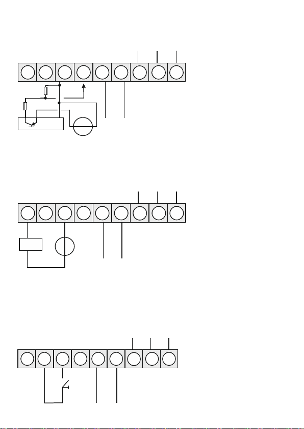
3. electrical connection
3.3. Switching points
Connection examples
NPN-output GND switching
GND
S2S1
_ +
9-28 VDC
Relais
X
9 8 7 6 5 4 3 2 1
Automatic reset with output 2 and manual reset with external button
Schaltpunkte
9 8 7 6 5 4 3 2 1
GND S2 S1
Reset

12
3. electrical connection
PNP-output L+-switching
9 8 7 6 5 4 3 2 1
_ +
9-28 VDC
XRL
__
L+
Push-Pull-output UV and GND-switching
98 7 6 5 4 3 2 1
_ +
9-28 VDC
_
L+
IN1
IN2
L+
GND
SPS
GND
_
_ _

13
4. Functional description and operation
Key symbol Function in operating mode Function during parameterization
Program key [P] The program key [P] is used to
switch to parameterization. Change to a lower parameter level or
to the stored value.
Minus key [▼]
The minus key [▼] can be used
to call up the min value or change
a lower limit value, depending on
the key function set.
Switching between parameters and
changing parameters in the value
level.
Plus key [▲]
The plus key [▲] can be used to
call up the max value or change a
lower limit value, depending on
the key function set.
Switching between parameters and
changing parameters in the value
level.
4. Functional description and operation
4.1. Operating and display elements
The display has 3 keys with which you can parameterize the device and call up stored functions
during operation. Functions that can be adjusted or changed are always signaled with a flashing
of the display. The settings made in the parameter level are always confirmed with [P] and thus
saved. However, the display also automatically saves all adjustments and switches to operating
mode if there are no further key operations within 10 seconds.
A switched on relay or an activated switching point is visually signaled by a lighting of the
respective switching point LED next to the 7-segment display.
A display overflow/underflow is indicated by 4 bars "- - - -".
Numerical values are adjusted from the smallest to the largest digit with [▲] [▼]and confirmed
digit-selectively with [P]. A minus sign can only be parameterized on the most significant digit.
After the last digit, the display switches back to the menu level.
Example: Setting of device parameters, e.g. selection of input signal
Parameter Selection option
Example: Setting numerical values, e.g. measuring range end value

14
4. Functional description and operation / 5. Setting the display
4.2. Programming via configuration software PM-TOOL:
Part including the software on CD, is a USB cable with device adapter. The connection is
established via a 4-pin micromatch connector on the back of the device and to the PC side with a
USB connector.
System requirements: PC with USB interface
Software: Windows XP, Windows VISTA
With this tool the device configuration can be generated, omitted and saved on the PC. Through
the easy-to-use program interface, the parameters can be changed, whereby the mode of
operation and the possible selection options are specified by the program.
ATTENTION!
When setting parameters with a measuring signal connected, make sure that the measuring
signal does not have a ground reference to the programming plug.
The programming adapter is not galvanically isolated and is directly connected to the PC.
Reversing the polarity of the input signal can cause a current to flow through the adapter and
destroy the device and connected components!
5.1. Switch on
After completing the installation, you can put the device into operation by applying the supply
voltage. Before doing so, check all electrical connections once again to ensure that they are
correctly connected.
Start sequence
During the switch-on procedure, the segment test (8 8 8 8), the message of the software type and
afterwards for the same time the software version are displayed for 1 second. The start sequence
is followed by the change to the operating or display mode.
5. Setting the display

15
6.1. Input signal selection: type
With the type setting an assignment of the input variant takes place, here can be selected
between the five input types voltage, current, Pt100(0), thermocouple and impulse signal.
6. Parameterization
6. Parameterization
Measurement signal
selection
Measuring signal
Special
parameters
General display
parameters
Alarm parameters
Safety
parameters
Voltage
see page 15-18
Power
see page 15-18
Pt100(0)
see page 19
Thermocouple
see page 19
Impulse input
see page 20-22
Measuring time, moving averaging, start/end
value representation in the display, key function,
display flashing
see page 27
Limit value behavior, limit value message,
switching behavior, switching threshold,
hysteresis, delay
see page 28-30
Locking / releasing the parameterization
see page 30

16
Parameter Selection option Default
VoLt
AMPE
6. Parameterization
6.1.1. Device parameters for the assignment of voltage/current signals: VoLT, AMPE
VoLT: Four voltage signals are available for selection : 0-10 V, 0-2 V, 0-1 V and 0-50 mV
AMPE: Here you can choose between the following signals : 0-20 mA and 4-20 mA
Parameter Selection option Default
End to
at or additional
OFFS to
at or additional
dot.A to
EndA to
OFFA to
tArA to
ZErO to
OUEr
This manual suits for next models
2
Table of contents
Other promesstec Measuring Instrument manuals


