ProMinent DFXa Operating instructions

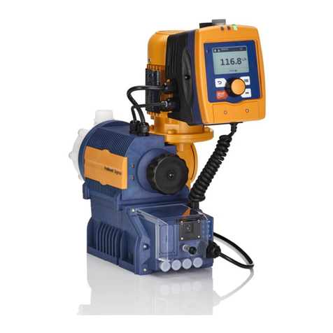
Peristaltic metering pump DULCO flex Control,
DFXa
Modules, options, accessories
Supplementary operating instructions
These instructions only apply in conjunction with the “Operating instructions for the peristaltic metering pump DULCO flex
Control, DFXa”
EN
Original operating instructions (2006/42/EC)Part no. 981282 Version: BA DX 040 11/21 EN
Please carefully read these operating instructions before use. · Do not discard.
The operator shall be liable for any damage caused by installation or operating errors.
The latest version of the operating instructions are available on our homepage.

Table of contents
1Supplementary operating instructions for CANopen............. 4
1.1 About this pump............................................................ 4
1.2 Control elements........................................................... 5
1.3 Electrical installation..................................................... 5
1.4 Emergency mode.......................................................... 7
1.5 Troubleshooting............................................................ 7
1.6 Accessories.................................................................. 8
1.7 Appendix....................................................................... 9
1.7.1 Communication Profile Area 0x1000-0x1FFF............ 9
1.7.2 Manufacturer Specific Profile Area
0x2000-0x5FFF......................................................... 9
1.7.3 Device Profile Area 0x6000-0x9FFF........................ 16
1.7.4 Alarm Action Area for Measurement Devices
(404 )....................................................................... 19
1.7.5 EMERGENCY.......................................................... 19
1.7.6 Explanations of objects............................................ 21
1.7.7 Changing the CANopen node address (Node ID)... 24
1.7.8 Transfer rate (baud rate).......................................... 24
1.7.9 Calibration, explanations......................................... 24
1.7.10 Firmware update.................................................... 25
1.7.11 Data storage.......................................................... 25
1.7.12 Directives / standards complied with..................... 25
2 Supplementary operating instructions for Modbus RTU..... 26
2.1 About this Modbus pump............................................ 26
2.2 Control elements......................................................... 27
2.3 Electrical installation................................................... 27
2.4 Setting options for the pump control elements........... 30
2.5 “Modbus RTU” implementation................................... 31
2.5.1 “Modbus RTU” message structure........................... 32
2.6 Device monitoring....................................................... 33
2.7 Emergency mode........................................................ 34
2.8 Functional faults.......................................................... 34
2.9 Accessories................................................................ 35
2.10 Modbus RTU for Prominent pumps register............. 35
2.10.1 “Device identification” register............................... 36
2.10.2 “Modbus” register................................................... 36
2.10.3 “Production data pump assembly-specific” reg‐
ister........................................................................ 37
2.10.4 “Production data Modbus module-specific” reg‐
ister........................................................................ 38
2.10.5 “Current operating parameters” register ............... 39
2.10.6 “Target operating parameter” register.................... 42
2.10.7 “Advanced configuration” register.......................... 43
2.10.8 “Accessories 1” register......................................... 46
2.10.9 “Accessories 3” register......................................... 46
2.10.10 “Debug data” register........................................... 47
3Supplementary operating instructions for PROFIBUS®...... 48
3.1 Requirements............................................................. 48
3.2 Setting the pump......................................................... 48
3.2.1 General.................................................................... 48
Table of contents
2

3.2.2 Switching PROFIBUS® to active / inactive............... 48
3.2.3 Setting the slave address........................................ 49
3.3 Special features in the active PROFIBUS® mode....... 50
3.3.1 General.................................................................... 50
3.3.2 Displays................................................................... 50
3.3.3 LEDs on the PROFIBUS® module........................... 50
3.4 Installation................................................................... 51
3.5 Operation.................................................................... 53
3.5.1 General.................................................................... 53
3.5.2 GSD file................................................................... 53
3.5.3 DULCO flex Control DFXa, DFXa data objects....... 53
4Supplementary operating instructions for PROFINET®...... 61
4.1 Requirements............................................................. 61
4.2 Setting the pump......................................................... 61
4.2.1 General.................................................................... 61
4.2.2 Activating / deactivating PROFINET®...................... 61
4.2.3 Configuring PROFINET®......................................... 62
4.3 Special features in active PROFINET® mode............. 63
4.3.1 General.................................................................... 63
4.3.2 Displays................................................................... 63
4.3.3 LEDs on the PROFINET® module........................... 64
4.4 Installation................................................................... 64
4.5 Operation.................................................................... 65
4.5.1 General.................................................................... 65
4.5.2 GSDML file.............................................................. 65
4.5.3 DULCO flex Control DFXa, DFXa data objects....... 66
4.5.4 PLC error and pump behaviour............................... 72
Table of contents
3

1 Supplementary operating instructions for CANopen
1.1 About this pump............................................................ 4
1.2 Control elements........................................................... 5
1.3 Electrical installation..................................................... 5
1.4 Emergency mode.......................................................... 7
1.5 Troubleshooting............................................................ 7
1.6 Accessories.................................................................. 8
1.7 Appendix....................................................................... 9
1.7.1 Communication Profile Area 0x1000-0x1FFF............ 9
1.7.2 Manufacturer Specific Profile Area
0x2000-0x5FFF......................................................... 9
1.7.3 Device Profile Area 0x6000-0x9FFF........................ 16
1.7.4 Alarm Action Area for Measurement Devices
(404 )....................................................................... 19
1.7.5 EMERGENCY.......................................................... 19
1.7.6 Explanations of objects............................................ 21
1.7.7 Changing the CANopen node address (Node ID)... 24
1.7.8 Transfer rate (baud rate).......................................... 24
1.7.9 Calibration, explanations......................................... 24
1.7.10 Firmware update.................................................... 25
1.7.11 Data storage.......................................................... 25
1.7.12 Directives / standards complied with..................... 25
1.1 About this pump
Metering pumps DULCO flex Control DFXa with CAN connector
differ from standard pumps in that they can be connected to a
CANopen bus system. A CAN pump DULCO flex Control DFXa
can be connected to a CANopen bus or used as a standalone unit.
Example:
nMeasurement value-dependent metering of sodium-calcium
hypochlorite into a swimming pool water circuit, in
‘CANopen’
operating mode, the pump being controlled by a controller.
A "CANopen" version of DULCO flex Control DFXa (Identity code
feature "Control type" = C or D) is designed for incorporation in a
CANopen system.
Supplementary operating instructions for CANopen
4

1.2 Control elements
P_G_0087_SW
2
3
1
Fig. 1: DFXa control elements
1 CAN bus status LEDs
2 "CAN bus" socket
3 Device LEDs
1.3 Electrical installation
CAUTION!
Pump may be damaged.
IP65 degree of protection cannot be guaranteed if
the CAN cable is not correctly screwed in.
– Manually screw in the CAN cable threaded
connectors until they reach the stop.
CAUTION!
Pump may be damaged.
The panel plug on the housing may break off.
– Never connect a T-distributor directly to the
housing. Fit a cable between the pump and the
T-distributor.
1. Connect the CAN cable to the CANopen bus connector as
shown below – for more details, refer to the documentation
for your CANopen installation.
2. Insert the mains plug into the power socket - the metering
pump may possibly start to pump.
Supplementary operating instructions for CANopen
5

9
7
8
6
5
5
8
13 14
P_G_0078_SW
Fig. 2: CAN connector for metering pumps (Example: 2 DFXa with
Dulcomarin II used as the control)
5 T-distributor, M 12, 5-pin CAN
6 Terminating resistor M 12 coupling
7 Terminating resistor M 12 plug
8 CAN connecting cable CAN connecting cable
9 CAN connecting cable
13 CAN pump DFXa e.g. for acid
14 CAN pump DFXa e.g. for alkali
Supplementary operating instructions for CANopen
6

A five-pin plug is used as the “CANopen bus connector”.
1 Shield
2 CAN V+ (supply voltage – not connected)
3 CAN GND (reference potential)
4 CAN H (bus line – dominant high)
5 CAN L (bus line – dominant low)
1.4 Emergency mode
You can guard against the possibility of the CANopen bus control
failing as follows:
1. Program an auxiliary frequency into the pump that fits best
with your process in emergency mode.
2. As soon as emergency mode is required, run the pump using
the "external control" terminal on the auxiliary frequency -
see "Operating instructions for the peristaltic metering
pump DULCO flex Control, DFXa" - "Installation, elec‐
trical".
Doing this will require an external cable and equip‐
ment to issue the auxiliary signal.
If you are in any doubt, seek the advice of our
technical support team.
1.5 Troubleshooting
The CANopen status LED indicates the status of the CAN connec‐
tion.
Operating and fault statuses are displayed by the 3 other LEDs -
see "Operating instructions for peristaltic metering pump DULCO
flex control DFXa”.
Connector for CANopen bus
1
54
2
3
P_BE_0059_SW
Fig. 3: Pump pin assignment (plug)
P_BE_0060_SW
Fig. 4: CAN cable assignment
(socket)
Supplementary operating instructions for CANopen
7

Tab. 1: Flash codes of CANopen status LED, top
Colour Flash code Cause Remedy
Green Lit Bus status
OPERATIONAL
- (Pump normal mode)
Green Flashing * Bus status
PRE-OPERATIONAL
Wait briefly or start pump
via bus
Green Single flashing ** Bus status
STARTUP
Wait briefly or set pump
for active bus operation -
see "Set-up" chapter
Green Off Error (BUSOFF, Error,…) Test CAN bus
Green Flickering Bus status
INIT
Wait briefly
*** ***
A0203
Ignore the flash codes for approx. 2 minutes after
connecting the metering pump.
For "Error messages about CANopen telegram",
see end of the appendix.
1.6 Accessories
Accessories Part no.
T-coupler M12 5-pin CAN 1022155
Terminating resistor M 12 coupling 1022154
Terminating resistor M 12 plug 1022592
Connecting cable - CAN, M 12, 5-pin, 1 m 1022139
Connecting cable - CAN, M 12, 5-pin, 2 m 1022140
Connecting cable - CAN, M 12, 5-pin, 5 m 1022141
Connecting cable - CAN, sold by the metre 1022160
CAN coupling, M 12, 5-pin Screw connector 1022157
CAN plug M 12, 5-pin Screw connector 1022156
Supplementary operating instructions for CANopen
8

1.7 Appendix
1.7.1 Communication Profile Area 0x1000-0x1FFF
Tab. 2: Transmit PDO MAPPING parameters
Index W Name Type Description Mapping
1A00h 0 TPDO1
1 DP_state U16 Metering pump status (base) 0x2A100010
2 DP_output_man (actual) U16 Dosing rate (actual) as a % of
the maximum possible dosing
rate
0x2A010010
1A01h 0 TPDO2
1 DP_level
OK level = value 100
Warning level = value 10
Error level = value 0
U8 Liquid level of dosing tank 0x2A050008
Tab. 3: Receive PDO MAPPING parameters
Index W Name Type Description Mapping
1600h 0 RPDO1
1 DP_output_cont U16 Dosing rate (target) as a % of
the maximum possible dosing
rate
0x2A000010
1601h 0 RPDO2
1 DP_batch_time_stamp U16 Batch trigger event 0x2A020010
1.7.2 Manufacturer Specific Profile Area 0x2000-0x5FFF
Index W Name Type Description Objects Attr
2A00h 0 DP_output_cont (target) U16 Dosing rate (target) as a % of
the maximum possible dosing
rate
RPDO1 wr
2A01h 0 DP_output_actual U16 Dosing rate (actual) as a % of
the maximum possible dosing
rate
TPDO1 ro
2A02h 0 DP_batch_time_stamp U16 Batch trigger event RPDO2 wo
2A03h 0 DP_batch_value U16 Batch factor RPDO2 wo
2A05h 0 DP_level
OK level = value 100
Warning level = value 10
Error level = value 0
U8 Liquid level of dosing tank TPDO2 ro
Supplementary operating instructions for CANopen
9

Index W Name Type Description Objects Attr
2A10h 0 DP_state U16 0=“Stop after Power On” con‐
figuration set,
1=Batch/contact memory func‐
tion active,
2=Pump calibrated,
3=Polarity of setpoint (1 = neg‐
ative, 0 = positive),
4=Priming 1 = active, 0 = not
active,
5=Warning,
6=Errors,
7=Collective stop,
8-11=Mode:
n0 = Halt
n1 = Continuous
n2 =Batch
n3 = Contact
n4 = Analogue
12=aux;
14=Pause,
15=Manual/Bus
n1 = Fieldbus mode
–additionally NO manual
stop
– OR priming active
n0 = Remaining mode
TPDO1 ro
2A11h 0 DP_Control U8 Bit 0 => Batch memory active
(activate)
Bit 1 => 0 = Positive/ 1 = nega‐
tive setpoint
Bit 2 => Pump calibrated (=1) /
not calibrated (=0)
Bit 6 => Trigger soft reset
SDO rw
2A12h 0 DP_mode U8 0 = Halt
1 = Continuous (Manual)
2 = Batch
3 = Contact
4 = Analogue
SDO wo
2A21h 0 DP_metering volume float Volume / rotation SDO wr
2A22h 0 DP_measuring_unit U8 0=litres,
1=gallons
SDO wr
2A30h 0 DP_volume U32 continuous metering volume (in
l) since the last reset
SDO ro
2A31h 0 DP_revol_cnt U16 Rotations since the last reset SDO ro
2A35h 0 PCO_HighestSubIndex U8 ro
Supplementary operating instructions for CANopen
10

Index W Name Type Description Objects Attr
2 BatchMem U8 Batch memory active SDO wo
3 ClearCount U8 Delete internal pump memory SDO wo
3FBBh 0 PCO_HighestSubIndex U8
1 U32 Identity code RO
2 U32 RO
3 U32 RO
4 U32 RO
5 U32 RO
6 U32 RO
7 U32 RO
8 U32 RO
3FBCh 0 PCO_HighestSubIndex U8
1 String Product designation (ASCII) RO
2 String RO
3 String RO
4 String RO
5 String RO
6 String RO
7 String RO
8 String RO
3FBDh 0 PCO_HighestSubIndex U8
1 String Hardware version (ASCII) RO
2 String RO
3 String RO
0x2A34 1 DP_quantity_left float Remaining metering in [l] (litres) SDO RO
0x2A40 1 DP_nominal_thoughput float Target dosing rate in [l/h] (litres/
hour)
SDO WR
0x2A41 1 DP_current_thoughput float Actual dosing rate in [l/h] (litres/
hour)
SDO RO
0x2A42 1 DP_maximal_thoughput float Maximum dosing rate in [l/h]
(litres/hour)
SDO RO
0x2A50 1 DP_nominal_concentration float Target final concentration in
[ppm]
SDO WR
0x2A51 1 DP_current_thoughput float Actual final concentration in
[ppm]
SDO RO
0x2A60 1 DP_state_extended U32 Extended status register SDO RO
Supplementary operating instructions for CANopen
11

Index W Name Type Description Objects Attr
Bit 0 = Manual stop
Bit 1 = Optional module stop
Bit 2 = Bluetooth stop
Bit 3 = Init stop after “Mains/
power supply on”
Bit 4 = Concentration mode
active
Bit 5 = Hose rupture sensor
connected
3FBEh 0 PCO_HighestSubIndex U8
1 String Software version (ASCII) RO
2 String RO
3 String RO
Supplementary operating instructions for CANopen
12

Tab. 4: 0x5100 – 0x5500
Index W Name Type Description
Max
Objects Attr
5100h 1 Switch-on
counter
U32 Switch-on counter SDO RO
5101h 1 Error flags U32 Bit 0 - Error, configuration data
(system)
Bit 1 - Error, current input too low
Bit 2 - Error, current input too high
Bit 3 - Error, level
Bit 4 - Error, hose rupture
Bit 6 - Error, directional change
Bit 7 - Error, temperature too high
Bit 8 - Error, initialisation (system)
Bit 9 - Reserved
Bit 10 - Error, invalid metering
parameter
Bit 11 - Reserved
Bit 12 - Reserved
Bit 13 - Error, undervoltage
Bit 14 - Reserved
Bit 15 - Error, hose change
aborted
Bit 16 - Error, memory overflow
Bit 17 - Error, input current less
than limit value
Bit 18 - Error, input current greater
than limit value
Bit 19 - Reserved
Bit 20 - Reserved
Bit 21 - Reserved
Bit 22 - Error, internal CAN bus
Bit 23 - Error, component version
compatibility
Bit 24 - Error, power unit configura‐
tion data
Bit 25 - Error, power unit initialisa‐
tion
Bit 26 - Speed control
Bit 27 - Error, fan
Bit 28 - Error, motor connection
Bit 29 - Error, motor status
Bit 30 - Error, motor blockage
Bit 31 - Error, power unit position
sensor
SDO RO
Supplementary operating instructions for CANopen
13

Index W Name Type Description
Max
Objects Attr
5102h 1 Warning flags U32 Bit 0 - Warning, level
Bit 1 - Warning, hose rupture
Bit 3 - Warning, metering volume
Bit 4 - Warning, invalid metering
parameter
Bits 5-11 - Reserved
Bit 12 - Warning, invalid metering
volume
Bit 13 - Warning, temperature
Bit 14 - Reserved
Bit 15 - Warning, speed control
(actual and target difference too
high)
Bits 16-31 - Reserved
SDO RO
5105h 1 Total rotation
counter
U32 Total rotation counter SDO RO
5106h 1 Metering quan‐
tity counter
float Metering quantity counter SDO RO
5108h 1 Remaining
metering
volume
float Remaining metering volume SDO RO
510Dh 1 Metering
volume per
trigger
Float Metering volume per trigger SDO RW
510Eh 1 Actual dosing
rate
Float Current dosing rate SDO RO
510Fh 1 Dosing time for
batch
U16 Dosing time for batch in sec SDO RW
5110h 1 Maximum
dosing rate
Float Maximum dosing rate SDO RO
5112h 1 Target dosing
rate
Float Target dosing rate SDO RW
5114h 1 Auxiliary dosing
rate
Float Auxiliary dosing rate SDO RW
5117h 1 Target oper‐
ating mode
U32 Target operating mode (0-Halt,1-
Manual,..)
SDO RW
5118h 1 Actual oper‐
ating mode
U32 Current operating mode SDO RO
5119h 1 Target sub-
operating mode
U32 Target sub-operating mode
(0-0..20 mA,1-4..20 mA,4 linear
curve,..)
SDO RW
511Ah 1 Actual sub-
operating mode
U32 Current sub-operating mode SDO RO
Supplementary operating instructions for CANopen
14

Index W Name Type Description
Max
Objects Attr
511Ch 1 Concentration-
controlled ope‐
ration on/off
U32 Concentration-controlled operation
on(1)/off(0)
SDO RW
511Eh 1 Duration of pri‐
ming
U16 Remaining duration of “Priming” SDO RW
5148h 1 Total operating
time
U32 Total operating time in hours (h) SDO RO
5152h 1 Calibration
factor
Float The calibration factor set in the
pump as a %
SDO RO
5153h 1 Deletable rota‐
tion counter
U32 Deletable rotation counter SDO RW
5154h 1 Deletable quan‐
tity counter
Float Deletable quantity counter SDO RW
Tab. 5: Strings
Index W Name Type Description Objects Attr
5042h 1 Identifica‐
tion_LED
U16 0 - Off SDO rw
>0 Set identi‐
fication time
(LED yellow
+red flash for
the duration)
1 is equiva‐
lent to
approx. 10
ms
5FEE 0 CANopen‐
StackRevi‐
sion
UINT32 ProMinent
CANopen-
Stack-Revi‐
sion
RO
Supplementary operating instructions for CANopen
15

1.7.3 Device Profile Area 0x6000-0x9FFF
Index Sub Name Type Description Categ.* Attr
6000h 00h HighestSubInde
x
U32 Failure codes MANDA RO
01h Hardware failure
codes 1
U32 MANDA RO
02h Hardware failure
codes 2
U32 MANDA RO
03h Software failure
codes 1
U32 Bit#0: Software fault MANDA RO
Bit#8 to 31
Reserved
04h Software failure
codes 2
U32 MANDA RO
05h Mechanics failure
codes 1
U32 MANDA RO
06h Mechanics failure
codes 2
U32 MANDA RO
07h Electrics failure
codes 1
U32 MANDA RO
08h Electrics failure
codes 2
U32 MANDA RO
0Dh Operation failure
codes 1
U32 MANDA RO
0Eh Operation failure
codes 2
U32 MANDA RO
0Fh Operation failure
codes 3
U32 MANDA RO
10h Auxiliary device
failure codes 1
U32 MANDA RO
11h Auxiliary device
failure codes 2
U32 MANDA RO
12h Auxiliary device
failure codes 3
U32 MANDA RO
Supplementary operating instructions for CANopen
16

Index Sub Name Type Description Categ.* Attr
6001h 00h HighestSubInde
x
U32 Warning codes MANDA RO
01h Hardware warning
codes 1
U32 MANDA RO
02h Hardware warning
codes 2
U32 MANDA RO
03h Software warning
codes 1
U32 Bit#0: Software‐
Warning
MANDA RO
04h Software warning
codes 2
U32 MANDA RO
05h Mechanics warning
codes 1
U32 MANDA RO
06h Mechanics warning
codes 2
U32 MANDA RO
07h Electrics warning
codes 1
U32 MANDA RO
08h Electrics warning
codes 2
U32 MANDA RO
0Dh Operation warning
codes 1
U32 MANDA RO
0Eh Operation warning
codes 2
U32 MANDA RO
0Fh Operation warning
codes 3
U32 MANDA RO
10h Auxiliary device
warning codes 1
U32 MANDA RO
11h Auxiliary device
warning codes 2
U32 MANDA RO
12h Auxiliary device
warning codes 3
U32 MANDA RO
Tab. 6: Category legend *
Abbreviation Full word
MANDA Mandatory
OPTION Optional
CONDIT Conditionally mandatory
Supplementary operating instructions for CANopen
17

Index Sub Name Type Description Categ.* Attr
6002h 00h HighestSubIndex U32 Alarm codes MANDA RO
01h Hardware alarm codes 1 U32 MANDA RO
02h Hardware alarm codes 2 U32 MANDA RO
03h Software alarm codes 1 U32
04h Software alarm codes 2 U32 MANDA RO
05h Mechanics alarm codes
1
U32 MANDA RO
06h Mechanics alarm codes
2
U32 MANDA RO
07h07 Electrics alarm codes 1 U32 MANDA RO
08h Electrics alarm codes 2 U32 MANDA RO
0Dh Operation alarm codes 1 U32 MANDA RO
0Eh Operation alarm codes 2 U32 MANDA RO
0Fh Operation alarm codes 3 U32 MANDA RO
10h Auxiliary device alarm
codes 1
U32 MANDA RO
11h Auxiliary device alarm
codes 2
U32 MANDA RO
12h Auxiliary device alarm
codes 3
U32 MANDA RO
Index Sub Name Type Description Categ.* Attr
6003h 00h HighestSubIndex U32 Specific physical
units
MANDA RO
01h Physical unit pres‐
sure
U32 Standard: bar
0x004E0000,
gal (AE)
MANDA RW
6005h 00h HighestSubIndex GenericPump con‐
trol
MANDA
01h Generic pump com‐
mands
U8 Pump stopped = 0,
Pump not stopped
= 1
MANDA RW
Bit#2: RemoteAc‐
cessReq:
No remote=0;
Remote access=1
Bits#3 to 7
Reserved
6007h 00h HighestSubIndex Identification MANDA RO
01h ManufacturerID String MANDA RO
02h DeviceType String MANDA RO
03h ProfileRevision String MANDA RO
Supplementary operating instructions for CANopen
18

Index Sub Name Type Description Categ.* Attr
6026h 00h HighestSubIndex Error notification
control
MANDA CO
02h Name String 0xA MANDA RW
03h Class String 0sB MANDA RW
07h NotificationCode U16 0 OPTION RW
6027h 00h HighestSubIndex Error notification
status
MANDA
01h Status U8 0 MANDA RO
Tab. 7: Category legend *
Abbreviation Full word
MANDA Mandatory
OPTION optional
CONDIT Conditionally mandatory
1.7.4 Alarm Action Area for Measurement Devices (404 )
Index Sub Name Type Description Categ. Attr
6519h 1 Al2_action =0 inac‐
tive
U8 Level min warning RW
6529h 1 Al3_action U8 Batch error RW
6539h 1 Al4_action U8 Cal warning RW
6549h 1 Al5_action U8 Sys error RW
6559h 1 Al6_action U8 Not bus RW
6569h 1 Al7_action U8 add2 RW
6579h 1 Al8_action U8 add3 RW
1.7.5 EMERGENCY
Tab. 8: Emergency Object Data:
Byte 0 1 2 3 4 5 6 7
Content* Emergency Error
Code*
Error reg‐
ister*
Manufacturer specific Error Field*
Tab. 9: *
Content (1 byte): 80h+Node-ID
Emergency Error Code (2 bytes): 0x1000 (0x10xx = Generic Error)
0x0000 (0x00xx = No Error)
Supplementary operating instructions for CANopen
19

Error Register (1001h content) (1 byte): 0x81 (Bit #0=Generic Error,Bit #7= Manufacturer-
specific)
Manufacturer-specific Error Field (5 bytes): Byte #3: Component no. (channel)
Byte #4: Error type
Byte #5: Error class
Byte #6: free
Byte #7: free
Emergency Error Code (2 bytes): 0xFF01 (0xFFxx = Device-specific)
Tab. 10: Manufacturer-specific Error Field (5 bytes):
Byte #3: Component number (channel)
Byte #4: Error type
Byte #5: Error class
Byte #6: free
Byte #7: free
Tab. 11: Component no. (channel):
0 -
1 DFXa
Tab. 12: Error type (1-99):
- see error table
Tab. 13: Error class:
Bit0 Emergency active
Bit1 Error (1) / warning (0)
Bit2 Action:
1 active (horn on) –
0 inactive (horn off)
Supplementary operating instructions for CANopen
20
Table of contents
Other ProMinent Control System manuals
Popular Control System manuals by other brands

Lamtec
Lamtec VMS Series manual

Julabo
Julabo PRESTO A80 Original operating manual

Leeson
Leeson SPEEDMASTER WASHGUARD 174102 Operation manual

Fasel Elektronik
Fasel Elektronik FCU-EXT-APP-CONTROL Installation

Dynamite
Dynamite Li-Po Glow Driver instructions

Desert Aire
Desert Aire GreenAire Installation and operation manual