Promise UltraTrack RM4000 User manual

U
LTRA
T
RAK
S
ERIES
RM4000,
SX4000,
RM8000,
SX8000,
RM15000
U
SER
M
ANUAL
Version 2.2

UltraTrak Series User Manual
ii
Copyright
© 2003, Promise Technology, Inc. All Rights Reserved.
Copyright by Promise Technology, Inc. (Promise Technology). No part of this
manual may be reproduced or transmitted in any form without the expressed,
written permission of Promise Technology.
Trademarks
Promise and the Promise logo are registered in U.S. Patent and Trademark
Office.
All other product names mentioned herein may be trademarks or registered
trademarks of their respective companies.
Important data protection information
You should back up all data before installing any drive controller or storage
peripheral. Promise Technology is not responsible for any loss of data resulting
from the use, disuse or misuse of this or any other Promise Technology product.
Notice
Although Promise Technology has attempted to ensure the accuracy of the
content of this manual, it is possible that this document may contain technical
inaccuracies, typographical, or other errors. Promise Technology assumes no
liability for any error in this publication, and for damages, whether direct, indirect,
incidental, consequential or otherwise, that may result from such error, including,
but not limited to loss of data or profits.
Promise Technology provides this publication “as is” without warranty of any
kind, either express or implied, including, but not limited to implied warranties of
merchantability or fitness for a particular purpose.
The published information in the manual is subject to change without notice.
Promise Technology reserves the right to make changes in the product design,
layout, and driver revisions without notification to its users.

iii
Radio Frequency Interference Statement
This equipment has been tested and found to comply with the limits for a Class
B digital device, pursuant to Part 15 of the FCC Rules. These limits are
designed to provide reasonable protection against harmful interference in a
residential installation. This equipment generates, uses and can radiate radio
frequency energy, and, if not installed and used in accordance with the
instruction may cause harmful interference to radio communications. However,
there is no guarantee that interference will not occur in a particular installation. If
this equipment does cause harmful interference to radio or television reception,
which can be determined by turning the equipment off and on, the user is
encouraged to try to correct the interference by one or more of the following
measures:
•Reorient or relocate the receiving antenna.
•Increase the separation between the equipment and receiver.
•Connect the equipment into an outlet on a circuit different from that to which
the receiver is connected.
•Consult Promise Technology, Inc. or an experienced radio/TV technician for
help.
This device complies with Part 5 of the FCC Rules. Operation is subject to the
following conditions: (1) This device may not cause harmful interference, and (2)
this device must accept any interference received, including interference that
may cause undesired operation.
Caution
Only digital device equipment CERTIFIED CLASS B should be
attached to this equipment and that must have shielded cables.

UltraTrak Series User Manual
iv

v
Contents
Chapter 1: Introduction...............................................................................................1
Architectural Description.......................................................................................1
Features and Benefits........................................................................................2
Chapter 2: RM4000 Setup..........................................................................................3
Unpack the UltraTrak............................................................................................3
Mount UltraTrak RM4000 in Rack.........................................................................4
Install Hard Drives ................................................................................................5
Connect the SCSI Cables.....................................................................................9
SCSI Termination ...............................................................................................10
SCSI Terminator..............................................................................................10
Daisy Chaining Multiple UltraTraks..................................................................11
Daisy Chaining with Other SCSI Devices ........................................................12
Connect the Power.............................................................................................13
Enter or Change the Password...........................................................................14
Create Your First Array.......................................................................................15
Create an Array Automatically.........................................................................15
Create an Array Manually................................................................................16
Assign a SCSI ID or LUN....................................................................................17
Activate In-Band SCSI........................................................................................19
Install the Promise RAID Console INF File (Windows only)................................20
Chapter 3: RM8000 Setup........................................................................................21
Unpack the UltraTrak..........................................................................................21
Mount UltraTrak RM8000 in Rack.......................................................................22
Install Hard Drives ..............................................................................................24
Connect the SCSI Cables...................................................................................28
SCSI Termination ...............................................................................................29
SCSI Terminator..............................................................................................30
Daisy Chaining Multiple UltraTraks..................................................................31
Daisy Chaining with Other SCSI Devices ........................................................32
Connect the Power.............................................................................................33
Main Power Switch ..........................................................................................33
Enter or Change the Password...........................................................................34
Your First Array...................................................................................................35
Create an Array Automatically.........................................................................35
Create an Array Manually................................................................................36
Assign a SCSI ID or LUN....................................................................................38
Activate In-Band SCSI........................................................................................40
Install the Promise RAID Console INF File (Windows only)................................41

UltraTrak Series User Manual
vi
Chapter 4: SX4000 and SX8000 Setup....................................................................43
Unpack the UltraTrak..........................................................................................43
Install Hard Drives ..............................................................................................44
Connect the SCSI Cables...................................................................................48
SCSI Termination ...............................................................................................49
SCSI Terminator..............................................................................................50
Daisy Chaining Multiple UltraTraks..................................................................51
Daisy Chaining with Other SCSI Devices ........................................................52
Connect the Power.............................................................................................53
Main Power Switch ..........................................................................................53
Enter or Change the Password...........................................................................54
Your First Array...................................................................................................56
Create an Array Automatically.........................................................................56
Create an Array Manually................................................................................57
Assign a SCSI ID or LUN....................................................................................58
Activate In-Band SCSI........................................................................................60
Install the Promise RAID Console INF File (Windows only)................................61
Chapter 5: RM15000 Setup......................................................................................63
Unpack the UltraTrak..........................................................................................63
Mount UltraTrak RM15000 in Rack.....................................................................64
Install Hard Drives ..............................................................................................65
Connect the SCSI Cables...................................................................................69
SCSI Termination ...............................................................................................69
SCSI Terminator..............................................................................................70
Daisy Chaining Multiple UltraTraks..................................................................71
Daisy Chaining with Other SCSI Devices ........................................................72
Connect the Power.............................................................................................73
Enter or Change the Password...........................................................................74
Your First Array...................................................................................................76
Create an Array Automatically.........................................................................76
Create an Array Manually................................................................................77
Assign a SCSI ID or LUN....................................................................................78
Activate In-Band SCSI........................................................................................80
Install the Promise RAID Console INF File (Windows only)................................81
Chapter 6: Array Maintenance..................................................................................83
Drive Status Indicators........................................................................................83
Meaning of Status Indicators ...........................................................................83
Critical & Offline Arrays.......................................................................................84
Rebuilding/Synchronizing Fault Tolerant Arrays..............................................84
When a Disk Drive Fails...................................................................................84
Replacing a Disk Drive.....................................................................................85
Expanding an Array............................................................................................87
Add a disk drive to the enclosure.....................................................................87
Add an installed disk drive to an array.............................................................87
RAID Conversion................................................................................................88
Convert an Array..............................................................................................90

vii
Chapter 7: Front Panel Interface..............................................................................91
The LCD Messages............................................................................................93
Idle Mode.........................................................................................................94
Initial Mode Menu.............................................................................................96
Configuration Menu..........................................................................................98
View Status Menu..........................................................................................100
Configure Array..............................................................................................105
Configure Cache............................................................................................121
Configure SCSI..............................................................................................122
Chapter 8: Technology Background.......................................................................127
Introduction to RAID .........................................................................................127
RAID 0 - Striping............................................................................................128
RAID 1 - Mirroring..........................................................................................129
RAID 0+1 - Striping / Mirroring.......................................................................130
RAID 3 - Block Striping with Dedicated Parity................................................131
RAID 5 - Block Striping with Distributed Parity...............................................132
RAID 30 - Striping of Dedicated Parity Arrays ...............................................133
RAID 50 - Striping of Distributed Parity Arrays ..............................................134
JBOD - Single Drive.......................................................................................135
Choosing a RAID Level ....................................................................................136
RAID 0...........................................................................................................136
RAID 1...........................................................................................................136
RAID 3...........................................................................................................137
RAID 5...........................................................................................................137
RAID 0+1.......................................................................................................137
RAID 30.........................................................................................................138
RAID 50.........................................................................................................138
JBOD.............................................................................................................139
Choosing Stripe Block Size ..............................................................................139
Gigabyte Boundary...........................................................................................139
Initialization.......................................................................................................140
Hot Spare Drive(s)............................................................................................140
Partition and Format the Array..........................................................................140
Chapter 9: In-Band SCSI........................................................................................141
UltraTrak Firmware...........................................................................................141
Enable the SCSI Base Management Option.....................................................142
Install the Promise RAID Console INF File (Windows only)..............................143
WebPAM ..........................................................................................................145
Verify In-Band SCSI Function...........................................................................146
SCSI ID Modes.................................................................................................147

UltraTrak Series User Manual
viii
Chapter 10: UltraTrak Maintenance .......................................................................149
Update UltraTrak Firmware...............................................................................149
Replace the Controller Card.............................................................................151
Remove the Controller Card..........................................................................151
Install the Controller Card..............................................................................152
Reset to Default Password...............................................................................153
Replace the Power Supply ...............................................................................154
RM8000/SX8000............................................................................................154
RM15000.......................................................................................................155
RM4000.........................................................................................................155
SX4000..........................................................................................................158
Chapter 11: Configuration Console Software.........................................................163
Password..........................................................................................................163
Listing Functions...............................................................................................164
Event List..........................................................................................................164
Tasking Functions.............................................................................................165
Disconnect........................................................................................................166
Chapter 12: Support...............................................................................................167
Frequently Asked Questions.............................................................................167
Contacting Technical Support...........................................................................169
Limited Warranty...............................................................................................171
Returning Product For Repair...........................................................................173
Appendix A: Serial Connector Pinout Diagrams.....................................................175
Index.......................................................................................................................177

1
Chapter 1: Introduction
Thank you for purchasing Promise Technology’s UltraTrak, external disk array
system. This manual covers the full UltraTrak line, including these models:
•RM4000
•SX4000
•RM8000
•SX8000
•RM15000
UltraTrak provides data storage solutions for applications where fault tolerance
and data redundancy are required. The failure of any single drive will not affect
data integrity or accessibility of the data. A defective drive may be replaced
without interruption of data availability to the host computer. A hot spare drive
will automatically replace a failed drive, securing the fault tolerant integrity of the
array. The self-contained hardware-based array provides maximum performance
in a compact external chassis.
The UltraTrak Series is an external disk array subsystem with an expandable
capacity of four to fifteen individual ATA disk drives.
The standard LVD SCSI interface provides compatibility with any system that
utilizes a SCSI interface. No vendor unique commands are required for the
operation of the disk array.
Architectural Description
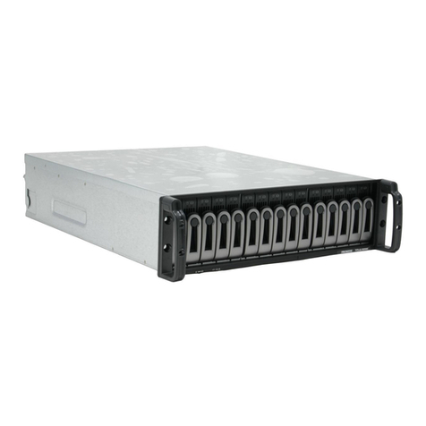
The UltraTrak RM4000 and SX4000 subsystems consist of four disk drive bays,
an enclosure with back plane, and the array controller. The UltraTrak RM8000
and SX8000 subsystems are similar except that they consist of eight disk drive
bays. Finally, the UltraTrak SM15000 is also the same except for its 15 disk
drive bays.
Multiple fans provide redundancy to ensure continued usage during component
failure. The array controller is hardware based and controls all array functions
transparently to the host system. UltraTrak appears to the computer’s operating
system as a standard SCSI drive.
Warning
The electronic components within the UltraTrak disk array are
sensitive to damage from ESD (Electro-Static Discharge).
Appropriate precautions should be observed at all times when
handling the array or its subassemblies.

UltraTrak Series User Manual
2
Features and Benefits
Feature Benefit
Maximum fault tolerance Ensures uninterrupted data availability.
Supports RAID levels 0, 1,
3, 5, 0+1 and JBOD Allows system to be tuned for maximum
performance.
Supports RAID levels 30
and 50 Applies to the RM8000, SX8000 and RM15000.
S.M.A.R.T Warns of disk drive degradation and potential
failure.
Emulates standard SCSI-3
drive to host Compatible with all SCSI-3 or SCSI-2/LVD host
adapters. No special operating system drivers
used.
Supports In-Band SCSI Allows you to manage multiple RAID subsystems
on the same SCSI chain from the same PC.
Tagged command queuing
up to 64 commands Maximum performance in Multi-Threaded
Operating Systems.
Front panel LCD and LED
indicators Easy setup and quick response to problems,
ensuring maximum up time and manageability.
Hot swap feature Allows a defective drive to be replaced without
interrupting data accessibility to the host system.
Hot-spare drive Maintains full fault tolerant integrity by
automatically rebuilding the data from a failed drive
to an installed hot spare drive.
Automatic background data
reconstruction when a drive
is replaced
Array is quickly back on-line with minimal user
intervention.
Redundant fans Load sharing and full operation even with a failed
fan

3
Chapter 2: RM4000 Setup
Getting started with the UltraTrak RM4000 consists of the following steps:
1. Unpack the UltraTrak storage subsystem (see below).
2. Mount UltraTrak RM4000 in a rack (page 4).
3. Install Hard Drives (page 5).
4. Connect the SCSI Cables (page 9).
5. SCSI Termination (page 10).
6. Connect the Power (page 13).
7. Enter or Change the Password (page 14).
8. Create an Array (page 15)
9. Assign a SCSI ID or LUN (page 17).
10. Activate In-Band SCSI (page 19).
11. Install the UltraTrak INF file on your RAID/Host PC (Windows only.
Page 20).
Unpack the UltraTrak
Open the UltraTrak box and carefully remove the UltraTrak unit and accessories
from the box. Be sure to remove the packing foam from within the UltraTrak
door. The UltraTrak and accessories include the following items:
•UltraTrak RM4000 Unit •External LVD SCSI cable
•Quick Start Guide •Power cord
•(2) Enclosure keys •(4) Screw sets for hard drives
•Null Modem Cable
•SCSI Terminator •CD with WebPAM Software
and User Manual, INF file, and
UltraTrak User Manual and
Quick Start Guide
Note
The Web-Based Promise Array Management (WebPAM)
software provides monitoring and maintenance of your RAID
through a graphic user interface (GUI) on your Web Browser.
Install WebPAM from the CD that comes with UltraTrak. You can
also download it from the Promise website (www.promise.com).
Using the In-Band SCSI feature, WebPAM will manage up to
seven UltraTrak systems per RAID/Host PC.
For a complete discussion of the In-Band SCSI feature on
UltraTrak, see Chapter 9: In-Band SCSI.

UltraTrak Series User Manual
4
Mount UltraTrak RM4000 in Rack
The UltraTrak may be installed in any convenient location within the LVD SCSI
cable length distance of the next SCSI device. The UltraTrak RM4000 is
designed specifically for rackmount installation but may also serve on a bench
top as well.
The UltraTrak RM4000 installs directly to the rack with or without a shelf.
Assemble the Mounting Brackets on each side of the RM4000 and set the unit
into the rack.
SEL EXIT
Figure 2. Rackmounted RM4000.
UltraTrak RM4000Rack Vertical Post
Rackmounting Shelf (optional)

Chapter 2: RM4000 Setup
5
Install Hard Drives
Before using the UltraTrak you must first populate it with ATA hard drives. The
UltraTrak RM4000 can support up to four (4) hard drives and provide the
configurations listed below.
Number of Hard Drives
RAID Configuration Minimum Maximum
JBOD (Single Drive) 1 4
RAID 0 1 4
RAID 1 2 2
RAID 3 3 4
RAID 5 3 4
RAID 0+1 4 4
Caution
You may mix manufacturer type and drive size – however, best
performance is achieved when you populate the array with
identical models. For different drive sizes, the arrays will use the
smallest disk size.
Warning
The electronic components within the UltraTrak disk array are
sensitive to damage from Electro-Static Discharge (ESD).
Appropriate precautions should be observed at all times when
handling the array or its subassemblies.
Caution
Before installing a new hard drive, be sure the jumpers on the
new hard drives are set for single or master operation. Consult
the drive manual for the proper settings.

UltraTrak Series User Manual
6
Figure 3. UltraTrak front panel access.
Figure 4. UltraTrak disk drive access.
Drive Latch Handle
Front Panel Lock
Front Panel
Unlocked
Locked

Chapter 2: RM4000 Setup
7
Install new hard drives into the UltraTrak by doing the following:
1. Unlock and open the Front Panel Door (see Figure 3) on the UltraTrak.
2. Pull the Drive Carrier Latch Handle and remove an unused Drive Carrier
(see Figure 4) from the UltraTrak. Begin at the right and work left.
3. Carefully lay the hard drive into the drive carrier, with the drive’s connectors
facing the carrier’s connectors.
4. Slide the hard drive into the carrier so the drive’s ATA connector fits into the
carrier’s ATA connector.
5. Attach the Drive Carrier power cable to the hard drive (see below).
6. Lower the hard drive into the Drive Carrier so that the screw holes on the
bottom line up.
Figure 5. Drive Carrier.
7. Insert screws through the holes in the Drive Carrier and into the bottom of
the hard drive. Snug each screw. Be careful not to over tighten.
8. Slide the assembled Drive Carrier back into the chassis and press the
handle forward to lock the Drive Carrier.
9. Repeat steps 2 through 7 until all of your hard drives are installed.
Power Connector
Hard Drive Mounting
Holes (total of 4)
ATA
Connector
Insert the carrier into the
chassis this way.
Handle

UltraTrak Series User Manual
8
Important
Be sure each drive is securely fastened to its carrier. Proper
installation ensures adequate grounding and minimizes vibration.
Do not install drives with fewer than four screws.
1
4
Figure 6. RM4000 drives are numbered right to left.
Caution
If you plan to operate your UltraTrak with less than four hard disk
drives, install all four Drive Carriers into the Chassis, even if they
are not holding a drive.
Note
The Drive Carrier Latching Mechanism must be locked or the
disk drive will not power up. The power light comes on when the
mechanism is locked.

Chapter 2: RM4000 Setup
9
Connect the SCSI Cables
Installation of the UltraTrak disk array is very similar to the installation of a
standard SCSI drive. The SCSI connector accepts the standard 68-pin LVD
SCSI connector used on most LVD SCSI devices. Refer to your system and/or
SCSI host adapter manual for additional installation procedures that may apply
to your system or host adapter.
Figure 7. Back of UltraTrak RM4000.
Caution
To prevent possible damage to the array or system, ensure that
system power is OFF before connecting the cables.
Power Switch SCSI Input Connector Serial (DB-9) Connector
Power Connector SCSI Output Connector Serial (RJ-45) Connector

UltraTrak Series User Manual
10
SCSI Termination
Two 68-pin wide SCSI connectors are provided on the back of the enclosure for
connecting the array to the system. These connectors are used in one of two
ways:
•If the UltraTrak disk array is the only external SCSI device, or is the last
external device in a daisy-chained configuration, connect the incoming
cable (the one which is attached to the SCSI adapter) to the top connector
and install the external SCSI Terminator on the bottom connector.
•If the array is to be placed in the middle of a daisy-chained configuration,
connect the incoming cable (the one which is attached to the SCSI adapter)
to the top connector and connect the outgoing cable (the one which
continues on to other devices) to the bottom connector. In this case, no
terminator is required at the RM4000 but the last device in the daisy chain
must have a terminator.
Correct SCSI termination procedures require that the first and last devices on
the SCSI bus be terminated. If the first or last device is not terminated, or if
devices other than the first and last are terminated, erratic SCSI bus
performance may occur. Typically, the system or host adapter (SCSI card inside
the PC) is the first device and is already terminated. When installing the
RM4000 on a SCSI bus with other devices, be sure to observe the above rules
with all devices on the SCSI bus. Consult your system and/or host adapter
manual for additional information on correct termination procedure.
Caution
Proper termination and SCSI-3 compliant cables are required for
the system to operate correctly. An external SCSI terminator and
a SCSI-3 compliant cable are included with the UltraTrak
RM4000.
SCSI Terminator
When the UltraTrak is the last SCSI device in the chain you must install the
Promise-supplied (or equivalent) external SCSI terminator on the SCSI Output
Connector (see below).

Chapter 2: RM4000 Setup
11
Figure 8. SCSI Terminator Installation.
Daisy Chaining Multiple UltraTraks
Use a standard 68-pin SCSI-3 cable assembly to attach the array to the SCSI
chain. Attach each cable to the individual units to be connected on the SCSI
bus. Ensure that each device has a unique SCSI ID (see page 17) and that the
last UltraTrak has a terminator.
Figure 9. Daisy Chaining several UltraTraks together.
Computer or Workstation SCSI Terminator
on last UltraTrak
SCSI Cable
UltraTrak RM4000s
SCSI Terminator SCSI Output
Connector

UltraTrak Series User Manual
12
Daisy Chaining with Other SCSI Devices
This procedure is essentially the same as the procedure outlined above for
multiple arrays. Refer to the manual associated with the other device or devices
for additional information that may be pertinent to that unit.
Ensure that each device has a unique SCSI ID (see page 17) and that only the
first and last devices are terminated. Some devices have an internal SCSI
termination function that takes the place of an external terminator attached to
the SCSI connector.
Figure 10. Daisy Chaining UltraTrak with other SCSI devices.
Computer or Workstation SCSI Termination on last device
SCSI Cable
UltraTrak RM4000
Other SCSI Device
UltraTrak RM4000
This manual suits for next models
4
Table of contents
Other Promise Disk Array System manuals

Promise
Promise UltraTrak100 TX4 User manual

Promise
Promise VTrack M-Class M200f User manual

Promise
Promise VTrak 15110 User manual

Promise
Promise VTrak 15110 User manual

Promise
Promise VTrak copy VTM210 User manual

Promise
Promise VessRAID 1000i Series User manual

Promise
Promise VTrak J310S User manual

Promise
Promise ultratrak SX4000 User manual

Promise
Promise VessRAID 1000f Series User manual

Promise
Promise PegasusPro Series User manual