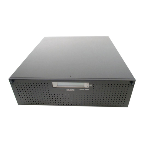
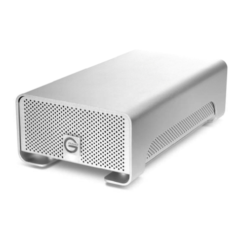
Promise VTrack M-Class M200f User manual

VTRAK
M-C
LASS
M500f,M500i,M500p,M300f,M300i,M300p,
M200f,M200i,M200p
P
RODUCT
M
ANUAL
Version 1.5 / SR-3

VTrak M-Class Product Manual
ii
Copyright
© 2006 Promise Technology, Inc. All Rights Reserved.
Copyright by Promise Technology, Inc. (Promise Technology). No part of this
manual may be reproduced or transmitted in any form without the expressed,
written permission of Promise Technology.
Trademarks
Promise, and the Promise logo are registered in U.S. Patent and Trademark
Office. All other product names mentioned herein may be trademarks or
registered trademarks of their respective companies.
Important data protection information
You should back up all data before installing any drive controller or storage
peripheral. Promise Technology is not responsible for any loss of data resulting
from the use, disuse or misuse of this or any other Promise Technology product.
Notice
Although Promise Technology has attempted to ensure the accuracy of the
content of this manual, it is possible that this document may contain technical
inaccuracies, typographical, or other errors. Promise Technology assumes no
liability for any error in this publication, and for damages, whether direct, indirect,
incidental, consequential or otherwise, that may result from such error, including,
but not limited to loss of data or profits.
Promise Technology provides this publication “as is” without warranty ofany kind,
either express or implied, including, but not limited to implied warranties of
merchantability or fitness for a particular purpose.
The published information in the manual is subject to change without notice.
Promise Technology reserves the right to make changes in the product design,
layout, and driver revisions without notification to its users.
This version of the User Manual supersedes all previous versions.
Recommendations
In the manual, the appearance of products made by other companies, including,
but not limited to software, servers, and disk drives, is for the purpose of
illustration and explanation only. Promise Technology does not recommend,
endorse, prefer or support any product made by another manufacturer.

iii
Contents
Chapter 1: Introduction . . . . . . . . . . . . . . . . . . . . . . . . . . . . . . . . . . . . .1
About This Manual . . . . . . . . . . . . . . . . . . . . . . . . . . . . . . . . . . . . . . .1
Overview . . . . . . . . . . . . . . . . . . . . . . . . . . . . . . . . . . . . . . . . . . . . . .2
Architectural Description . . . . . . . . . . . . . . . . . . . . . . . . . . . . . . . . . .3
Features and Benefits . . . . . . . . . . . . . . . . . . . . . . . . . . . . . . . . . . .4
Specifications . . . . . . . . . . . . . . . . . . . . . . . . . . . . . . . . . . . . . . . . . .6
M500f/i/p . . . . . . . . . . . . . . . . . . . . . . . . . . . . . . . . . . . . . . . . . . .6
M300f/i/p, M200f/i/p . . . . . . . . . . . . . . . . . . . . . . . . . . . . . . . . . .8
FCC Statement . . . . . . . . . . . . . . . . . . . . . . . . . . . . . . . . . . . . . .9
Chapter 2: Installation . . . . . . . . . . . . . . . . . . . . . . . . . . . . . . . . . . . . .11
Unpack the VTrak . . . . . . . . . . . . . . . . . . . . . . . . . . . . . . . . . . . . . .11
Mount VTrak M500f/i/p in a Rack . . . . . . . . . . . . . . . . . . . . . . . . . .12
Mount VTrak M300f/i/p or M200f/i/p in a Rack . . . . . . . . . . . . . . . .14
Install Disk Drives . . . . . . . . . . . . . . . . . . . . . . . . . . . . . . . . . . . . . .16
Drive Numbering . . . . . . . . . . . . . . . . . . . . . . . . . . . . . . . . . . . .18
Set Up Network Cable Connections . . . . . . . . . . . . . . . . . . . . . . . .20
Fibre Channel Storage Area Network. . . . . . . . . . . . . . . . . . . .20
Fibre Channel Direct Attached Storage . . . . . . . . . . . . . . . . . .21
iSCSI Storage Area Network . . . . . . . . . . . . . . . . . . . . . . . . . .22
iSCSI Direct Attached Storage . . . . . . . . . . . . . . . . . . . . . . . . .23
SCSI Direct Attached Storage . . . . . . . . . . . . . . . . . . . . . . . . .24
Set Up Serial Cable Connections . . . . . . . . . . . . . . . . . . . . . . . . . .25
Connect the Power . . . . . . . . . . . . . . . . . . . . . . . . . . . . . . . . . . . . .26
Chapter 3: Setup . . . . . . . . . . . . . . . . . . . . . . . . . . . . . . . . . . . . . . . . .29
VTrak Setup with CLI or CLU . . . . . . . . . . . . . . . . . . . . . . . . . . . . .29
CLI: Fibre Channel and SCSI Models (M500f/p, M300f/p, M200f/p)
30
CLI: iSCSI Models (M500i, M300i, M200i) . . . . . . . . . . . . . . . .30
CLU: Fibre Channel and SCSI Models (M500f/p, M300f/p, M200f/p)
32
CLU: iSCSI Models (M500i, M300i, M200i) . . . . . . . . . . . . . . .34
Install iSCSI Initiator on the Host PC . . . . . . . . . . . . . . . . . . . . . . . .39
Software-based iSCSI Initiator . . . . . . . . . . . . . . . . . . . . . . . . .39
VTrak Setup with WebPAM PROe . . . . . . . . . . . . . . . . . . . . . . . . .41
Log-in to WebPAM PROe . . . . . . . . . . . . . . . . . . . . . . . . . . . . .41
Language Selection . . . . . . . . . . . . . . . . . . . . . . . . . . . . . . . . .44
Create a Disk Array . . . . . . . . . . . . . . . . . . . . . . . . . . . . . . . . . .45
Additional Logical Drives . . . . . . . . . . . . . . . . . . . . . . . . . . . . . .54

VTrak M-Class Product Manual
iv
Chapter 3: Setup, continued
Log-out of WebPAM PROe . . . . . . . . . . . . . . . . . . . . . . . . . . . .54
Internet Connection using WebPAM PROe . . . . . . . . . . . . . . .55
Chapter 4: Management with WebPAM PROe . . . . . . . . . . . . . . . . . .57
VTrak Status Indicators . . . . . . . . . . . . . . . . . . . . . . . . . . . . . . . . . .57
Drive Status Indicators . . . . . . . . . . . . . . . . . . . . . . . . . . . . . . . . . .59
Audible Alarm . . . . . . . . . . . . . . . . . . . . . . . . . . . . . . . . . . . . . . . . .60
Log-in/Log-out . . . . . . . . . . . . . . . . . . . . . . . . . . . . . . . . . . . . . . . . .61
Log-in to WebPAM PROe . . . . . . . . . . . . . . . . . . . . . . . . . . . . .61
Log-out of WebPAM PROe . . . . . . . . . . . . . . . . . . . . . . . . . . . .63
Graphic User Interface . . . . . . . . . . . . . . . . . . . . . . . . . . . . . . . . . .64
Header . . . . . . . . . . . . . . . . . . . . . . . . . . . . . . . . . . . . . . . . . . .65
Tree View . . . . . . . . . . . . . . . . . . . . . . . . . . . . . . . . . . . . . . . . .67
Management Window . . . . . . . . . . . . . . . . . . . . . . . . . . . . . . . .68
Event Frame . . . . . . . . . . . . . . . . . . . . . . . . . . . . . . . . . . . . . . .68
Subsystems . . . . . . . . . . . . . . . . . . . . . . . . . . . . . . . . . . . . . . . . . . .68
Subsystem . . . . . . . . . . . . . . . . . . . . . . . . . . . . . . . . . . . . . . . .69
Administrative Tools . . . . . . . . . . . . . . . . . . . . . . . . . . . . . . . . . . . .75
User Management . . . . . . . . . . . . . . . . . . . . . . . . . . . . . . . . . .75
Network Management . . . . . . . . . . . . . . . . . . . . . . . . . . . . . . . .81
Fibre Channel Management . . . . . . . . . . . . . . . . . . . . . . . . . . .83
iSCSI Management . . . . . . . . . . . . . . . . . . . . . . . . . . . . . . . . . .88
SCSI Management . . . . . . . . . . . . . . . . . . . . . . . . . . . . . . . . . .95
Storage Services . . . . . . . . . . . . . . . . . . . . . . . . . . . . . . . . . . . .97
Software Management . . . . . . . . . . . . . . . . . . . . . . . . . . . . . .100
Export . . . . . . . . . . . . . . . . . . . . . . . . . . . . . . . . . . . . . . . . . . .109
Import . . . . . . . . . . . . . . . . . . . . . . . . . . . . . . . . . . . . . . . . . . .109
Firmware Update . . . . . . . . . . . . . . . . . . . . . . . . . . . . . . . . . .110
Restore Factory Defaults . . . . . . . . . . . . . . . . . . . . . . . . . . . .110
Clear Statistics . . . . . . . . . . . . . . . . . . . . . . . . . . . . . . . . . . . .111
Shutdown and Restart . . . . . . . . . . . . . . . . . . . . . . . . . . . . . .111
Controllers . . . . . . . . . . . . . . . . . . . . . . . . . . . . . . . . . . . . . . . . . . .113
Controller . . . . . . . . . . . . . . . . . . . . . . . . . . . . . . . . . . . . . . . .114
Enclosures . . . . . . . . . . . . . . . . . . . . . . . . . . . . . . . . . . . . . . . . . . .117
Identify Enclosure . . . . . . . . . . . . . . . . . . . . . . . . . . . . . . . . . .118
Enclosure . . . . . . . . . . . . . . . . . . . . . . . . . . . . . . . . . . . . . . . .119
Physical Drives . . . . . . . . . . . . . . . . . . . . . . . . . . . . . . . . . . . . . . .122
Physical Drive . . . . . . . . . . . . . . . . . . . . . . . . . . . . . . . . . . . . .124
Disk Arrays . . . . . . . . . . . . . . . . . . . . . . . . . . . . . . . . . . . . . . . . . .128
Disk Array . . . . . . . . . . . . . . . . . . . . . . . . . . . . . . . . . . . . . . . .133

Contents
v
Chapter 4: Management with WebPAM PRO, continued
Logical Drives . . . . . . . . . . . . . . . . . . . . . . . . . . . . . . . . . . . . . . . .141
Logical Drive . . . . . . . . . . . . . . . . . . . . . . . . . . . . . . . . . . . . . .143
Spare Drives . . . . . . . . . . . . . . . . . . . . . . . . . . . . . . . . . . . . . . . . .150
Create Spare Drive . . . . . . . . . . . . . . . . . . . . . . . . . . . . . . . .151
Delete Spare Drive . . . . . . . . . . . . . . . . . . . . . . . . . . . . . . . . .152
Spare Check – All Spare Drives . . . . . . . . . . . . . . . . . . . . . . .152
Spare Drive . . . . . . . . . . . . . . . . . . . . . . . . . . . . . . . . . . . . . . .153
Logical Drive Summary . . . . . . . . . . . . . . . . . . . . . . . . . . . . . . . . .155
Chapter 5: Management with the CLU . . . . . . . . . . . . . . . . . . . . . . .157
VTrak Status Indicators . . . . . . . . . . . . . . . . . . . . . . . . . . . . . . . . .157
Drive Status Indicators . . . . . . . . . . . . . . . . . . . . . . . . . . . . . . . . .159
Audible Alarm . . . . . . . . . . . . . . . . . . . . . . . . . . . . . . . . . . . . . . . .160
CLU Connection . . . . . . . . . . . . . . . . . . . . . . . . . . . . . . . . . . . . . .161
Serial Connection . . . . . . . . . . . . . . . . . . . . . . . . . . . . . . . . . .161
Telnet Connection . . . . . . . . . . . . . . . . . . . . . . . . . . . . . . . . . .161
Exit the CLU . . . . . . . . . . . . . . . . . . . . . . . . . . . . . . . . . . . . . .163
CLU Function Map . . . . . . . . . . . . . . . . . . . . . . . . . . . . . . . . . . . . .164
Quick Setup . . . . . . . . . . . . . . . . . . . . . . . . . . . . . . . . . . . . . . . . . .173
Subsystem Management . . . . . . . . . . . . . . . . . . . . . . . . . . . . . . . .173
Alias . . . . . . . . . . . . . . . . . . . . . . . . . . . . . . . . . . . . . . . . . . . .173
Media Patrol . . . . . . . . . . . . . . . . . . . . . . . . . . . . . . . . . . . . . .173
Lock Management . . . . . . . . . . . . . . . . . . . . . . . . . . . . . . . . .173
System Date and Time . . . . . . . . . . . . . . . . . . . . . . . . . . . . . .174
Controller Management . . . . . . . . . . . . . . . . . . . . . . . . . . . . .174
Controller Settings . . . . . . . . . . . . . . . . . . . . . . . . . . . . . . . . .174
Enclosure Management . . . . . . . . . . . . . . . . . . . . . . . . . . . . .176
Enclosure Status . . . . . . . . . . . . . . . . . . . . . . . . . . . . . . . . . . .176
Enclosure Settings . . . . . . . . . . . . . . . . . . . . . . . . . . . . . . . . .177
Batteries . . . . . . . . . . . . . . . . . . . . . . . . . . . . . . . . . . . . . . . . .178
Locate Enclosure . . . . . . . . . . . . . . . . . . . . . . . . . . . . . . . . . .179
Physical Drive Management . . . . . . . . . . . . . . . . . . . . . . . . . . . . .179
Global Physical Drive Settings . . . . . . . . . . . . . . . . . . . . . . . .179
Individual Physical Drive Settings . . . . . . . . . . . . . . . . . . . . . .180
Force Physical Drive Offline/Online . . . . . . . . . . . . . . . . . . . .181
Locate Physical Drive . . . . . . . . . . . . . . . . . . . . . . . . . . . . . . .181
Disk Array Management . . . . . . . . . . . . . . . . . . . . . . . . . . . . . . . .182
Create a Disk Array . . . . . . . . . . . . . . . . . . . . . . . . . . . . . . . . .182
Delete a Disk Array . . . . . . . . . . . . . . . . . . . . . . . . . . . . . . . . .184
Disk Array Information . . . . . . . . . . . . . . . . . . . . . . . . . . . . . .185

VTrak M-Class Product Manual
vi
Chapter 5: Management with the CLU, continued
Disk Array Settings and Functions . . . . . . . . . . . . . . . . . . . . .185
Locate Disk Array . . . . . . . . . . . . . . . . . . . . . . . . . . . . . . . . . .187
Create a Logical Drive . . . . . . . . . . . . . . . . . . . . . . . . . . . . . .187
Delete a Logical Drive . . . . . . . . . . . . . . . . . . . . . . . . . . . . . . .188
Logical Drive Management . . . . . . . . . . . . . . . . . . . . . . . . . . . . . .188
Logical Drive Information . . . . . . . . . . . . . . . . . . . . . . . . . . . .189
Logical Drive Settings and Functions . . . . . . . . . . . . . . . . . . .189
Locate Logical Drive . . . . . . . . . . . . . . . . . . . . . . . . . . . . . . . .190
Network Management . . . . . . . . . . . . . . . . . . . . . . . . . . . . . . . . . .191
Management Port Settings . . . . . . . . . . . . . . . . . . . . . . . . . . .191
iSCSI Port Settings . . . . . . . . . . . . . . . . . . . . . . . . . . . . . . . . .191
Fibre Channel Management . . . . . . . . . . . . . . . . . . . . . . . . . . . . .192
Node . . . . . . . . . . . . . . . . . . . . . . . . . . . . . . . . . . . . . . . . . . . .192
Ports . . . . . . . . . . . . . . . . . . . . . . . . . . . . . . . . . . . . . . . . . . . .192
Fibre Channel Initiators . . . . . . . . . . . . . . . . . . . . . . . . . . . . . .194
iSCSI Management . . . . . . . . . . . . . . . . . . . . . . . . . . . . . . . . . . . .195
Node . . . . . . . . . . . . . . . . . . . . . . . . . . . . . . . . . . . . . . . . . . . .195
Ports . . . . . . . . . . . . . . . . . . . . . . . . . . . . . . . . . . . . . . . . . . . .195
Sessions . . . . . . . . . . . . . . . . . . . . . . . . . . . . . . . . . . . . . . . . .196
iSNS . . . . . . . . . . . . . . . . . . . . . . . . . . . . . . . . . . . . . . . . . . . .196
SLP . . . . . . . . . . . . . . . . . . . . . . . . . . . . . . . . . . . . . . . . . . . . .196
CHAP . . . . . . . . . . . . . . . . . . . . . . . . . . . . . . . . . . . . . . . . . . .197
Ping . . . . . . . . . . . . . . . . . . . . . . . . . . . . . . . . . . . . . . . . . . . . .197
SCSI Management . . . . . . . . . . . . . . . . . . . . . . . . . . . . . . . . . . . .198
Channel Information . . . . . . . . . . . . . . . . . . . . . . . . . . . . . . . .198
Channel Settings . . . . . . . . . . . . . . . . . . . . . . . . . . . . . . . . . . .198
Target Information . . . . . . . . . . . . . . . . . . . . . . . . . . . . . . . . . .199
Background Activity . . . . . . . . . . . . . . . . . . . . . . . . . . . . . . . . . . . .199
Background Activity Settings . . . . . . . . . . . . . . . . . . . . . . . . .200
Background Activities List . . . . . . . . . . . . . . . . . . . . . . . . . . . .200
Event Viewer . . . . . . . . . . . . . . . . . . . . . . . . . . . . . . . . . . . . . . . . .201
Runtime Events . . . . . . . . . . . . . . . . . . . . . . . . . . . . . . . . . . . .201
NVRAM Events . . . . . . . . . . . . . . . . . . . . . . . . . . . . . . . . . . . .201
Additional Info and Management . . . . . . . . . . . . . . . . . . . . . . . . . .202
Spare Drive Management . . . . . . . . . . . . . . . . . . . . . . . . . . . .202
LUN Mapping (Fibre Channel and iSCSI) . . . . . . . . . . . . . . . .203
LUN Mapping (SCSI) . . . . . . . . . . . . . . . . . . . . . . . . . . . . . . .204
User Management . . . . . . . . . . . . . . . . . . . . . . . . . . . . . . . . .205
Software Management . . . . . . . . . . . . . . . . . . . . . . . . . . . . . .207
Flash through TFTP . . . . . . . . . . . . . . . . . . . . . . . . . . . . . . . .212

Contents
vii
Chapter 5: Management with the CLU, continued
Clear Statistics . . . . . . . . . . . . . . . . . . . . . . . . . . . . . . . . . . . .212
Restore Factory Defaults . . . . . . . . . . . . . . . . . . . . . . . . . . . .212
Shutdown and Restart . . . . . . . . . . . . . . . . . . . . . . . . . . . . . .213
Buzzer . . . . . . . . . . . . . . . . . . . . . . . . . . . . . . . . . . . . . . . . . . . . . .214
Chapter 6: Maintenance . . . . . . . . . . . . . . . . . . . . . . . . . . . . . . . . . .215
Firmware Update – WebPAM PROe . . . . . . . . . . . . . . . . . . . . . . .217
Firmware Update – CLU . . . . . . . . . . . . . . . . . . . . . . . . . . . . . . . .219
Replace Power Supply – All Models . . . . . . . . . . . . . . . . . . . . . . .220
Replace Cooling Unit Fan – M500f/i/p . . . . . . . . . . . . . . . . . . . . . .221
Replace Cooling Unit Fan – M300f/i/p and M200f/i/p . . . . . . . . . .226
Replace Cache Battery – M500f/i/p . . . . . . . . . . . . . . . . . . . . . . . .230
Replace Cache Battery – M300f/i/p and M200f/i/p . . . . . . . . . . . .233
Replace SEP – M500f/i/p . . . . . . . . . . . . . . . . . . . . . . . . . . . . . . .235
Replace SEP – M300f/i/p and M200f/i/p . . . . . . . . . . . . . . . . . . . .236
Replace RAID Controller – All Models . . . . . . . . . . . . . . . . . . . . . .237
Chapter 7: Technology Background . . . . . . . . . . . . . . . . . . . . . . . .239
Introduction to RAID . . . . . . . . . . . . . . . . . . . . . . . . . . . . . . . . . . .239
Choosing a RAID Level . . . . . . . . . . . . . . . . . . . . . . . . . . . . . . . . .247
Stripe Size . . . . . . . . . . . . . . . . . . . . . . . . . . . . . . . . . . . . . . . . . . .250
Sector Size . . . . . . . . . . . . . . . . . . . . . . . . . . . . . . . . . . . . . . . . . .250
Cache Policy . . . . . . . . . . . . . . . . . . . . . . . . . . . . . . . . . . . . . . . . .251
Read Cache Policy . . . . . . . . . . . . . . . . . . . . . . . . . . . . . . . . .251
Write Cache Policy . . . . . . . . . . . . . . . . . . . . . . . . . . . . . . . . .252
Cache Line Size . . . . . . . . . . . . . . . . . . . . . . . . . . . . . . . . . . .252
Capacity Coercion . . . . . . . . . . . . . . . . . . . . . . . . . . . . . . . . . . . . .252
Initialization . . . . . . . . . . . . . . . . . . . . . . . . . . . . . . . . . . . . . . . . . .253
Hot Spare Drive(s) . . . . . . . . . . . . . . . . . . . . . . . . . . . . . . . . . . . . .253
Partition and Format the Logical Drive . . . . . . . . . . . . . . . . . . . . .254
RAID Level Migration . . . . . . . . . . . . . . . . . . . . . . . . . . . . . . . . . . .254
Ranges of Disk Array Expansion . . . . . . . . . . . . . . . . . . . . . .256
Media Patrol . . . . . . . . . . . . . . . . . . . . . . . . . . . . . . . . . . . . . . . . .257
Predictive Data Migration (PDM) . . . . . . . . . . . . . . . . . . . . . . . . . .257
PDM Triggers . . . . . . . . . . . . . . . . . . . . . . . . . . . . . . . . . . . . .257
Transition . . . . . . . . . . . . . . . . . . . . . . . . . . . . . . . . . . . . . . . . . . . .258
Example . . . . . . . . . . . . . . . . . . . . . . . . . . . . . . . . . . . . . . . . .259

VTrak M-Class Product Manual
viii
Chapter 8: Troubleshooting . . . . . . . . . . . . . . . . . . . . . . . . . . . . . . .261
VTrak is Beeping . . . . . . . . . . . . . . . . . . . . . . . . . . . . . . . . . . . . . .261
LEDs Display Amber or Red . . . . . . . . . . . . . . . . . . . . . . . . . . . . .262
Front Panel . . . . . . . . . . . . . . . . . . . . . . . . . . . . . . . . . . . . . . .262
Drive Status Indicators . . . . . . . . . . . . . . . . . . . . . . . . . . . . . .264
Back of Enclosure . . . . . . . . . . . . . . . . . . . . . . . . . . . . . . . . . .265
CLU Reports a Problem . . . . . . . . . . . . . . . . . . . . . . . . . . . . . . . .268
WebPAM PROe Reports a Problem . . . . . . . . . . . . . . . . . . . . . . .269
Event Notification Response . . . . . . . . . . . . . . . . . . . . . . . . . . . . .271
Critical & Offline Disk Arrays . . . . . . . . . . . . . . . . . . . . . . . . . . . . .286
When a Disk Drive Fails . . . . . . . . . . . . . . . . . . . . . . . . . . . . .286
With a Hot Spare Drive . . . . . . . . . . . . . . . . . . . . . . . . . . . . . .286
Without a Hot Spare Drive . . . . . . . . . . . . . . . . . . . . . . . . . . .287
Rebuild Operation . . . . . . . . . . . . . . . . . . . . . . . . . . . . . . . . .287
Enclosure Problems . . . . . . . . . . . . . . . . . . . . . . . . . . . . . . . . . . .289
Connection Problems . . . . . . . . . . . . . . . . . . . . . . . . . . . . . . . . . .292
SCSI Connections . . . . . . . . . . . . . . . . . . . . . . . . . . . . . . . . . .292
iSCSI Connections . . . . . . . . . . . . . . . . . . . . . . . . . . . . . . . . .293
Serial Connections . . . . . . . . . . . . . . . . . . . . . . . . . . . . . . . . .293
Network Connections . . . . . . . . . . . . . . . . . . . . . . . . . . . . . . .294
Unsaved Data in the Controller Cache . . . . . . . . . . . . . . . . . . . . .295
Chapter 9: Support . . . . . . . . . . . . . . . . . . . . . . . . . . . . . . . . . . . . . .297
Frequently Asked Questions . . . . . . . . . . . . . . . . . . . . . . . . . . . . .297
Contact Technical Support . . . . . . . . . . . . . . . . . . . . . . . . . . . . . .299
Limited Warranty . . . . . . . . . . . . . . . . . . . . . . . . . . . . . . . . . . . . . .302
Returning Product For Repair . . . . . . . . . . . . . . . . . . . . . . . . . . . .303
Appendix A: Useful Information . . . . . . . . . . . . . . . . . . . . . . . . . . . .305
Serial Connector Pinout . . . . . . . . . . . . . . . . . . . . . . . . . . . . . . . . .305
SNMP MIB Files . . . . . . . . . . . . . . . . . . . . . . . . . . . . . . . . . . . . . .306
Index. . . . . . . . . . . . . . . . . . . . . . . . . . . . . . . . . . . . . . . . . . . . . . . . . . .307

1
Chapter 1: Introduction
• About This Manual (below)
• Overview (page 2)
• Architectural Description (page 3)
• Specifications (page 6)
Thank you for purchasing Promise Technology’s VTrak M-Class external disk
array subsystem.
About This Manual
This Product Manual describes how to setup, use, and maintain the VTrak M-
Class external disk array subsystem. It also describes how to use the built-in
command-line interface (CLI), command-line utility (CLU), and embedded Web-
based Promise Array Management—Professional (WebPAM PROe) software.
This manual includes a full table of contents, index, chapter task lists, and
numerous cross-references to help you find the specific information you are
looking for.
Also included are four levels of notices:
Note
A Note provides helpful information such as hints or alternative
ways of doing a task.
Important
An Important calls attention to an essential step or point required
to complete a task. Important items include things often missed.
Caution
A Caution informs you of possible equipment damage or loss of
data and how to avoid them.
Warning
A Warning notifies you of probable equipment damage or loss of
data, or the possibility of physical injury, and how to avoid them.

VTrak M-Class Product Manual
2
Overview
VTrak provides data storage solutions for applications where high performance
and data protection are required. The failure of any single drive will not affect data
integrity or accessibility of the data in a RAID protected logical drive.
Figure 1. VTrak M500f/i/p front view
Figure 2. VTrak M300f/i/p front view (M200f/i/p is similar)
A defective drive may be replaced without interruption of data availability to the
host computer. If so configured, a hot spare drive will automatically replace a
failed drive, securing the fault-tolerant integrity of the logical drive. The self-
contained hardware-based RAID logical drive provides maximum performance in
a compact external chassis.
PROMISE VTrak M500
Drive Carrier LEDs
Power and Status LEDs Drive Carriers
Drive Carrier LEDs
Drive Carriers Power and Status LEDs

Chapter 1: Introduction
3
Figure 3. VTrak M500f Rear View (M500i/p have different controllers)
Figure 4. VTrak M300i/M200i Rear View (M300f/M200f and M300p/M200p
have different controllers)
Architectural Description
The VTrak M-Class is a Direct Attached Storage (DAS) subsystem that can also
function in a Storage Area Network (SAN). The subsystem supports 1.5 Gb/s and
3.0 Gb/s SATA drives:
• VTrak M500f/i/p supports up to 15 disk drives in a 3U enclosure
• VTrak M300f/i/p supports up to 12 disk drives in a 2U enclosure
• VTrak M200f/i/p supports up to 8 disk drives in a 2U enclosure
Mgmt IOIOI
Controller
12
FC 1 FC 2
Storage Enclosure
Processor (SEP) Fibre Channel
RAID Controller
Power Supply Cooling Unit
with Battery Power SupplyCooling Unit
iSCSI 1 iSCSI 2
IOIOI
Controller
Mgmt
Cooling Unit
with Battery
Power Supply 1 iSCSI
RAID
Controller
Power Supply 2Storage
Enclosure
Processor
(SEP)

VTrak M-Class Product Manual
4
All M-Class enclosures include a mid-plane, RAID controller, power and cooling
units; and enclosure processor all in one cable-less chassis design. Multiple fans
and power supplies provide redundancy to ensure continued usage during
component failure. The RAID controller is hardware based and controls all logical
drive functionstransparently to the host system. VTrak appears to the computer’s
operating system as a standard SCSI drive or drives.
Features and Benefits
Feature Benefit
M500f/i/p: 3U 19-inch wide
enclosure Installs easily in any standard rackmount.
M300f/i/p and M200f/i/p: 2U 19-
inch wide enclosure Installs easily in any standard rackmount.
Supports RAID levels 0, 1, 1E, 5,
10, and 50 Allows system to be tuned for maximum
performance.
Supports online logical drive
(array) expansion Lets you add disk drives to an existing
logical drive without interrupting data
accessibility
Supports online RAID migration Allows you to convert a logical drive from
one RAID level to another without
interrupting data accessibility
Supports Serial ATA drives Allows you to use existing SATA disk drives.
Supports logical drive migration
from other Promise RAID products Allow you to seamlessly move your existing
logical drives to VTrak without recreating
them.
S.M.A.R.T. monitoring Warns of disk drive degradation and
potential failure.
Up to 25K IOPS (over two Fibre
Channel or two iSCSI ports) High processing rate.
1 Gb or 2 Gb sustained bandwidth
(Fibre Channel) High data thoughput.
Up to 1 Gb/sec sustained
bandwidth (iSCSI) High data thoughput.

Chapter 1: Introduction
5
Hardware-assisted XOR engine High-speed parity calculation for parity type
logical drives.
Supports out-of-band management
through RS232 and 10/100/1000
BaseT Ethernet connections
Allows you to manage the RAID subsystem
while maximizing bandwidth on the iSCSI
network.
Supports SNMP (v2) CIM and
WBEM standards API-ready for enterprise management
integration.
Tagged Command Queuing (TCQ)
up to 128 commands Maximum performance in Multi-Threaded
Operating Systems.
Supports SATA II Native Command
Queuing High performance and efficiency through
efficient command re-ordering.
Supports DDF compliant metadata
on disk Enabled disk array migration from one
controller to another.
Hot-swap feature for drive carriers,
power supplies, fans, and battery Allows a defective component to be
replaced without interrupting data
accessibility to the host system.
Tool-less field-replaceable units
(FRUs) All FRUs can be replaced without tools,
saving time and effort for support personnel.
Hot-spare drives Maintains full fault tolerant integrity by
automatically rebuilding the data from a
failed drive to an installed hot spare drive.
Supports multiple, designated and global
spares.
Automatic background data
reconstruction when a drive is
replaced
Logical drive is quickly back on-line with
minimal user intervention.
Redundant, hot-swappable cooling
units Load sharing and full operation even with
multiple failed fans.
N+1 Redundant, hot-swappable
power supplies Load sharing and full operation even with a
failed power supply.
Redundant Fibre Channel ports (f
models) Load sharing and full operation even with a
failed FC port.
Feature Benefit

VTrak M-Class Product Manual
6
Specifications
M500f/i/p
Drive Capacity: 15 SATA disk drives (3.5" x 1" form factor only).
External I/O Ports (M500f): Dual 1-Gb/2-Gb Fibre Channel ports.
External I/O Ports (M500i): Dual 1-Gb iSCSI ports
External I/O Ports (M500p): Dual 320-MB SCSI ports
Sustained Throughput (M500f): Up to 4 Gb/s (over two FC ports).
Sustained Throughput (M500i): Up to 2 Gb/s (over two iSCSI ports)
Sustained Throughput (M500p): Up to 640 MB/s (over two SCSI ports)
Sustained I/Os: Up to 25,000 I/Os per second.
Data Cache: 256MB predictive data cache with automatic write cache destaging
and 72-hour battery backup protection.
Supported RAID Levels:
Redundant iSCSI ports (i models) Load sharing and full operation even with a
failed iSCSI port.
Redundant SCSI ports (p models) Load sharing and full operation even with a
failed SCSI port.
Cluster support Supports two- and four-node server clusters
for performance and availability.
Complete cable-less design All components easily plug directly into
boards. No cables to complicate setup or
maintenance.
Cache battery backup Up to 72-hour backup for controller cache to
retain data in case of power failure.
Command-line and graphic-user
interfaces Choice of control and monitoring methods
for greater flexibility.
•RAID0•RAID1•RAID1E
•RAID5 •RAID10 •RAID50
Feature Benefit

Chapter 1: Introduction
7
Any combination of these RAID levels can exist at once on separate logical
drives. See page 239 for more information on RAID.
RAID Flexibility: Configurable RAID stripe size – 8, 16, 32, 64, 128, 256, 512 KB,
and 1 MB sectors per disk.
Rebuild priority tuning: Adjustment of minimum I/O reserved for server use during
rebuild.
Hot-spares: Multiple global and designated hot spares.
Maximum LUNs: 32 per array in any combination of RAID levels and drive types.
256 LUNs total.
Supported Disk Interfaces: Serial ATA (SATA)
Supported Operating Systems:
Current: 8 A @ 100 VAC; 4 A @ 200 VAC (max. rating with two power cords)
Power Consumption: 440 watts
Power Supply: Dual 500W, 100–240 VAC auto-ranging, 50–60 Hz, dual hot swap
and redundant with PFC, N+1 design
Thermal Output: 1590 BTU/hour (max current)
Operating Temperature: 41° to 104°F (5° to 40°C)
Non-operational Temperature: -40° to 140°F (-40° to 60°C)
Relative Humidity: Maximum 90%
Vibration: Random, 0.21 grms, 5 to 500Hz, 30Mins, X, Y, Z axis
Management Tools: WebPAM PROe, Command Line Utility, Command Line
Interface
Management Interfaces: Ethernet, RS232 (Serial)
Management Protocols: SNMP, SSL, WBEM, Telnet
Notification: Email, audible, and visible alarms
Dimensions: Height, 5.12 in (13.00 cm); Width, 17.48 in (44.40 cm); Depth, 22.17
in (56.30 cm)
Weight: 68.34 lbs (31.00 Kg) without drives; 84.88 lbs (38.50 Kg) with 15 drives
installed
• Windows 2000
• Windows XP Professional
• Windows 2003
• RedHat Linux
• SuSE Linux
• Novell Netware
• Sun Solaris

VTrak M-Class Product Manual
8
Safety Certifications: CE, FCC Class A, BSMI, VCCi, cUL, TUV, MIC
Limited Warranty: 3 Years (See page 302 for details)
M300f/i/p, M200f/i/p
Drive Capacity (M300f/i/p): 12 SATA disk drives (3.5" x 1" form factor only).
Drive Capacity (M200f/i/p): 8 SATA disk drives (3.5" x 1" form factor only).
External I/O Ports (M300f/M200f): Dual 1-Gb/2-Gb Fibre Channel ports.
External I/O Ports (M300i/M200i): Dual 1-Gb iSCSI ports
External I/O Ports (M300p/M200p): Dual 320-MB SCSI ports
Sustained Throughput (M300f/M200f): Up to 4 Gb/s (over two FC ports).
Sustained Throughput (M300i/M200i): Up to 2 Gb/s (over two iSCSI ports)
Sustained Throughput (M300p/M200p): Up to 640 MB/s (over two SCSI ports)
Sustained I/Os: Up to 25,000 I/Os per second.
Data Cache: 256MB predictive data cache with automatic write cache destaging
and 72-hour battery backup protection.
Supported RAID Levels:
Any combination of these RAID levels can exist at once on separate logical
drives. See page 239 for more information on RAID.
RAID Flexibility: Configurable RAID stripe size – 8, 16, 32, 64, 128, 256, 512 KB,
and 1 MB sectors per disk.
Rebuild priority tuning: Adjustment of minimum I/O reserved for server use during
rebuild.
Hot-spares: Multiple global and designated hot spares.
Maximum LUNs: 32 in any combination of RAID levels and drive types.
Supported Disk Interfaces: Serial ATA (SATA)
•RAID0•RAID1•RAID1E
•RAID5 •RAID10 •RAID50

Chapter 1: Introduction
9
Supported Operating Systems:
Current: 8 A @ 100 VAC; 4 A @ 200 VAC (max. rating with two power cords)
Power Consumption: 340 watts
Power Supply: Dual 400W, 100–240 VAC auto-ranging, 50–60 Hz, dual hot swap
and redundant with PFC, N+1 design
Thermal Output: 1160 BTU/hour (max current)
Operating Temperature: 41° to 104°F (5° to 40°C)
Non-operational Temperature: -40° to 140°F (-40° to 60°C)
Relative Humidity: Maximum 90%
Vibration: Random, 0.21 grms, 5 to 500Hz, 30Mins, X, Y, Z axis
Management Tools: WebPAM PROe, Command Line Utility, Command Line
Interface
Management Interfaces: Ethernet, RS232 (Serial)
Management Protocols: SNMP, SSL, WBEM, Telnet
Notification: Email, audible, and visible alarms
Dimensions: Height, 3.50 in (8.90 cm); Width, 17.56 in (44.60 cm); Depth, 22.09
in (56.10 cm)
Weight: M300f/i/p, 55.12 lbs (25.00 Kg) without drives; 68.34 lbs (31.00 Kg) with
12 drives installed
Weight: M200f/i/p, 50.71 lbs (23.00 Kg) without drives; 59.52 lbs (27.00 Kg) with
8 drives installed
Safety Certifications: CE, FCC Class A, BSMI, VCCi, cUL, TUV, MIC
Limited Warranty: 3 Years (See page 302 for details)
FCC Statement
This device complies with Part 15 of the FCC Rules. Operation is subject to the
following two conditions: (1) this device may not cause harmful interference, and
(2) this device must accept any interference received, including interference that
may cause undesired operation.
• Windows 2000
• Windows XP Professional
• Windows 2003
• RedHat Linux
• SuSE Linux
• Novell Netware
• Sun Solaris

VTrak M-Class Product Manual
10

11
Chapter 2: Installation
• Unpack the VTrak storage subsystem (below)
• Mount VTrak M500f/i/p in a Rack (page 12)
• Mount VTrak M300f/i/p or M200f/i/p in a Rack (page 14)
• Install Disk Drives (page 16)
• Set Up Network Cable Connections (page 20)
• Set Up Serial Cable Connections (page 25)
• Connect the Power (page 26)
Unpack the VTrak
The VTrak box contains the following items:
•VTrakUnit
• Quick Start Guide
• Null Modem Cable
• Left and right mounting rails
• 1.0m External VHDCI SCSI
cables (2 for M500p/M300p, 1
for M200p)
• Screws for disk drives
(36 for M200f/i/p; 52 for M300f/i/p;
64 for M500f/i/p; including 4 spares)
• 1.5m (4.9 ft) Power cords (2)
• CD with SNMP files, Product
Manual and Quick Start Guide
Warning
The electronic components within the VTrak disk array are
sensitive to damage from Electro-Static Discharge (ESD).
Observe appropriate precautions at all times when handling the
VTrak or its subassemblies.
Important
Use the following categories of network cables with VTrak:
• Cat 6, preferred
• Cat 5E, minimum

VTrak M-Class Product Manual
12
Mount VTrak M500f/i/p in a Rack
Figure 1. Rackmounted VTrak M500f/i/p
The VTrak M500f/i/p installs directly to the rack with or without using the supplied
mounting rails.
Figure 2. Mounting rail installation
PROMISE VTrak M500f
Vertical Rack Post
Direct attach to post Mounting Rail
(included)
VTrak M500f/i/p
VTrak attaching screw
Back side of post
Rack front post
Rail attaching screw
(not included)
Rail adjustment screw
Mounting
Rail
Rail attaching screw
(not included)
Back side
of post
Rack rear post
VTrak subsystem
This manual suits for next models
8
Table of contents
Other Promise Disk Array System manuals

Promise
Promise VTrak 15110 User manual

Promise
Promise ultratrak SX4000 User manual

Promise
Promise VTrak J310S User manual

Promise
Promise VessRAID 1000i Series User manual

Promise
Promise VTrak copy VTM210 User manual

Promise
Promise E610f User manual

Promise
Promise VessRAID 1000f Series User manual

Promise
Promise PegasusPro Series User manual

Promise
Promise UltraTrak100 TX4 User manual

Promise
Promise VTrak 15110 User manual