PROMIX SM305 User manual
1
OPERATING MANUAL
Technical description. Installation manual. Certificate.
PATENT FOR INVENTION
No.2615712
11.09.2019
1.
PURPOSE
Electromechanical locks series Promix-SM305 with a hook-shaped locking mechanism
(below called the locks) are intended for locking swing plastic doors and windows which can be
opened remotely by energizing/de-energizing (depending on the version) the lock with DC supply
voltage by means of switches (buttons) or controllers of access monitoring and control systems,
audio and video intercoms, code panels or other devices. The lock can be mounted on both right
and left doors and windows.
2.
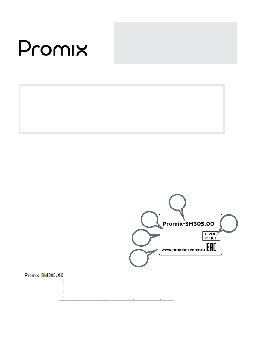
LABELING
The label stuck to the lock body contains
the following information:
1. Lock model.
2. Patent number.
3. Nominal supply voltage.
4. Nominal consumed current.
5. Date of manufacture and QCD mark
6. Identification number.
7. Manufacturer’s website.
For the list of lock modifications that can be ordered, see 5.2.
The color of the product is shown on the sticker stuck to the box, after the product name. Series
colors:
White
.
Other colors are provided optionally.
2
5
3,4
6,7
An example of information
layout on the label.
ELECTROMECHANICAL LOCK
Promix-SM305
Patent No. 2615712
12 V=0.1 A
Made in Russia
No. 100 001008
Supply voltage:
0 - 12V.
Version:
0 - normally opened, 1 - normally closed
engineering and production center
ELECTROMECHANICAL LOCK
1
Promix-SM305
2
Check completeness of the lock set when buying! After buying, the
manufacturer will not accept claims related to incomplete set.
3.
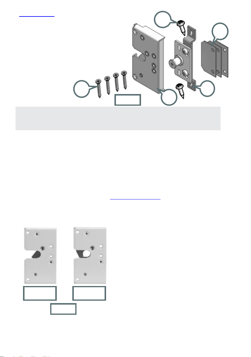
SET OF DELIVERY
4.
DESIGN AND PRINCIPLE OF OPERATION
The locks are produced in two versions: normally opened (NO), and normally closed (NC).
NO lock is in the open state when de-energized and in the closed state when voltage is supplied.
NC lock is in the closed state when no voltage is supplied, and in the open state when the lock is
energized. For opening the lock, it is necessary to de-energize a normally open lock or to supply
voltage to a normallyclosed lock.
The external body of the lock and the matching latch plate have a special standard shape and
a suitable for the majority of plastic shapes. Examples of the lock mounting on plastic shapes of
various configurations see at the website www.promix-center.com
As the door is closed, the latch enters the slot in the lock and, overcoming the catch hook
force, is fixed transferring the catch hook from “open” position to “closed” position. As supply
voltage is applied (or, for a normally closed version, as the lock is de-energized), the catch hook
is blocked in the "closed"position and locks the latch.
There is a possibility of emergency opening of the lock
by means of the release lever (see 7.1).
There are adjustments to the position ofthe bolt in the
horizontal and vertical planes. To correct the position
of the roller depending on the gap between the door
frame and the door, adjusting gaskets 3 are used (see
6.2, Fig.6).
The design allows the ignition of the normally open-
type to normally closed and Vice versa (see 7.2).
1 –Lock
1 pc.
2 –Latch assembled with plate
1 pc.
3 –Adjustment pad
3 pcs.
4 –Self-tapping screw 3.3х30
(countersunk)
4 pcs.
5 –Self-tapping screw 3.5х25 (cup head)
2 pcs.
6 –Operating manual
1 pc.
“Open”
position
“Closed”
position
1
2
3
4
5
Fig.1
Fig.2

Promix-SM305
3
NC locks are not intended for outdoor installation. NO lock can be mounted
outdoors on condition that it is energized for most time.
5.
TECHNICAL DATA
5.1 OPERATING CONDITIONS
The lock operation environment must be explosion-safe, free of current-conducting dust or
gases that cause metal corrosion and destroying insulation of current conductors and electric
elements, free of current-carrying dust or water vapor, and preventing ingress of water, steam,
fuel and lubricants.
Climatic conditions of operation –У3.1 as per GOST 15150-69 with extended temperature
range:
ambient temperature: from -30 to +50 °С;
Relative air humidity: not higher than 98% at 25°С or lower temperatures without moisture
condensation and hoar-frost formation;
installation indoors or outdoors excluding ingress of moisture, dust, dirt, etc. inside the lock.
5.2 TECHNICAL DATA
Modification
Promix-SM305.00
Promix-SM305.10
Version
normally opened
normally closed
DC supply voltage U, V
12±2
Current consumed, А
0.1 (at 12V)
Supply pulse duration (not more
than), s
not rated.
Minimum pause between
pulses, s
not rated.
Lock weight (
not more than
),
kg
0.3
Holding force (
not less than
),
kg
300
Power wire length, m
0.3
Allowable clearance between the
door frame and the door, mm
10-15

Promix-SM305
4
12-14.
60-70.
Lock and latch overall and mounting dimensions.
6.
INSTALLATION AND CONNECTION
6.1 LOCK AND LATCH MOUNTING
1. Drill a hole for lead-out of the power wire at the place of the lock installation.
2. Laythe power wire through the hole produced inside the shape slot and lead it to outside by
drilling the shape.
3. Apply the catch to the fittings slot of the door frame and fix it with self-tapping screws
4
.
4. Using a knife or a chisel, remove two projections 12-14 mm long in the door frame shape
(see Fig.5).
5. Insert the plate with the latch
2
in the slot of the door section so that the roller is at the center
of the lock slot (if the door shape slot is occupied with fittings, then the latch is mounted
without the base(see Fig.6).
Fig. 5
Fig. 6
Fig. 7
Latch base
Adjustment plate
Door frame
Door
Fig.4
Fig.3

Promix-SM305
5
See operating voltage range in 5.2. Avoid supply of overvoltage.
Provide a reliable electriccontact. To prevent short-circuit, insulate places of
connection.
6. Mark the edges of the latch plate.
7. Take off the latch and, using a knife or a chisel, remove aflush the projection in the shape to
a width of 60-70 mm (see Fig.7).
8. Mount the latch in the door shape slot and fix with self-tapping screws
5
.
6.2 LATCH ADJUSTMENT
It is necessary to adjust the latch position so that the latch, with the door closed, enters the
lock slot to complete operation of the catch hook. For adjustment in the vertical plane, loosen the
self-tapping screws
5
and shift the latch. For adjustment in the horizontal plane: screw out the
latch screws from the base, drill the necessary holes in the latch
plate, shift the latch, screw the screws into the new holes.
`
In case the clearance between the door and the door frame
is greater than the rated 12 mm (the latch does not reach the
lock slot), one or more adjustment shims
3
must be placed
between the plate and the latch plate (see Fig.6).
6.3 CONNECTING PROCEDURE
The lock operation is controlled by means of energizing and de-energizing. For this purpose, a
controller (control board) or a switch (button) is generally used. The controller is mounted in
accordance with its certificate.
Connect the lock power wires adhering to the following polarity:
Red (black with a red stripe) –positive pole of the power supply;
Black –negative pole of the power supply;
Application of voltage of reverse polarity does not provide the lock operability but does cause
its failure.
Example of the lock connection to the remote control system Promix-RDS.
7.
SPECIAL ASPECTS OF INSTALLATION AND
OPERATION
1)
The possibility of using of the locks for restriction of access to the premises and the place of
installation (outdoors or indoors) are determined by the
installation organization
on the
basis of the design features and the mounting method, room criticality level, the purpose of
Allowable clearance between the door frame and the door.
Lock
Controller Promix-CR.RX
Remote control
Promix-CR.TX
~220 V
Door (wing)
Door frame
10-15 mm
Fig. 8
Fig. 9
Promix-SM305
6
the access restriction regime and other factors (the presence of security providers, video
surveillance, etc.).
2) To prevent deformations of the door due to attempts to open the door with the lock closed, it is
recommended to mount the lock in the area of the door handle.
3) It is recommended to install the lock together with a door closer –this reduces impact load on
the lockand extends its service life.
4) Operation of an installed NC lock should be tested only if the supply voltage can be applied
thereto.
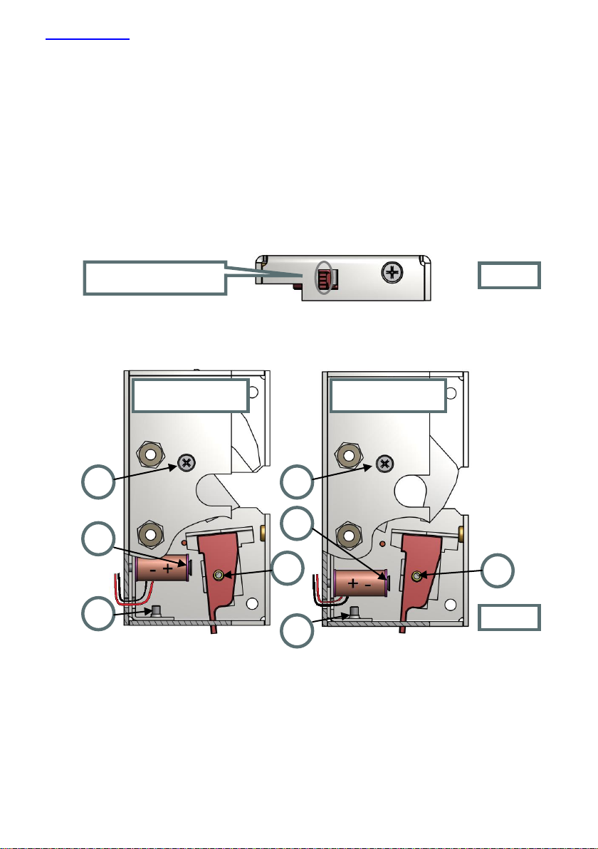
7.1 EMERGENCY OPENING
There is an emergency exit rod in the lock case. To mechanically open the lock, pull the
rod, moving it to the "open" position (see Fig.10) and then open the door.
7.2 LOCK TRANSFER FROM ONE VERSION TO
ANOTHER
The lock transfer from the normally open to normally closed version:
1. Unscrew three fastening screws
1
and take off the base.
2. Take off the thrust
2
from the base.
3. Unscrew the fastening screw
3
and remove the bracket of the solenoid.
4. Unscrew the fastening screw
4
and remove the coil and the angle.
5. Withdraw the fastening screw
4
from the coil and insert it in the reverse side of the coil.
6. Fix the coil with the turned angle
5
on the bracket with the screw in the adjacent threaded hole.
7. Mountthe bracket on the body and fix with the screw
3
.
8. Mount the rest on the axle
2
.
1
2
3
4
1
2
3
4
Normally opened version
Normally closed version
Emergency exit rod
Fig. 10
Fig. 11

Promix-SM305
7
The lock does not need lubrication!
The lock transfer from the normally closed to normally open version is
performed in a similar way.
9. Make sure of the lock operability, then mount the base passing the power wire through the slot,
and fix the base with screws
1
.
8.
TROUBLE-SHOOTING
Troubles and problems
Remedies
The lock does not fix the latch roller (the
door is not fixed in the closed state).
Check polarity and conformity of the lock supply
voltage to the required value.
Adjust the latch (see 6.2) so that, with the door
closed, the roller enters the snap slot before
operation of the catch hook.
The door is not closed completely since the
latch does not enter the snap.
Perhaps the catch hook was manually transferred
to the “closed” position (see Fig 2).
Deblock the catch hook and transfer it to the
“open” position manually.
The latch roller does not enter the snap
slot, or enters with friction.
Restore position of the door that changed in the
course of operation. If restoration is impossible,
adjust the latch (see 6.2)
The door is not opened when transferred to
the “open” state. To open the door, one has
to press it more snugly to the door frame.
Remove the causes of the non-tight door bearing
against the door frame.
Adjust the latch in the horizontal plane.
9.
MAINTENANCE
Maintenance of the lock is performed at least once every two monthsand includes:
Visual inspection of the lock to check reliability of fastening. If necessary, tighten fasteners
of the lock and the latch.
Checking the proper position of the latch (see section 6.2).
10.
STORAGE AND TRANSPORTATION
Prior to putting into operation, the locks must be stored in the manufacturer’s packing, in
rooms with an ambient temperature of -30 to +50 °С and a relative humidity not higher than 98%
at 25º С in compliance with storage conditions as per GOST 15150-69.
Locks transportation conditions must comply with group C as per GOST 23216-78 in terms of
exposure to mechanical factors, and Ж2 as per GOST 15150-69 in terms of exposure to climatic
factors.
11.
SAFETY REQUIREMENTS
The design of the locksensures safety of personnel involved in mounting and maintenance.
Due to low DC supply voltage, the products correspond to class III as per GOST 12.2.007.0-
75 and are electrically safe.

Promix-SM305
8
The warranted operation period is 12 months from the date of sale but not
longer than 18 months from the day of acceptance by the manufacturer’s QCD.
Faulty products are accepted for repair only together with the latch, on the
obligatory condition that factory labels are retained on the product body.
To improve product quality the manufacturing plant reserves the right to make
modifications to the product design without prior notice.
Fire safety of the locks is ensured by use of non-combustible or hardly combustible materials,
and low supply voltage.
12.
DISPOSAL
The product is not hazardous for human life and health or for the environment; disposal after
its service life is performed without taking any special measures for environment protection.
13.
WARRANTY LIABILITIES
The manufacturer, ETC PROMIX LLC, warrants conformity of Promix-SM305 locks to
requirements of current Technical Specifications provided that transportation, storage, installation
and operation rules established in this Manual are followed.
Within the period of warranty, ETC PROMIX LLC undertakes to repair defective products free
of charge. Expenses for transporting the product to the place of repair and back will be borne by
the Buyer.
Warranty liabilities do not cover any defects and damages caused by:
Improper maintenance by the Buyer;
Use of the product under conditions that do not comply with the operation requirements;
Mechanical damages or disassembly of the products bythe Buyer;
Non-observance of the transportation and storage rules.
On expiration of the warranty service period, the manufacturer provides after-warranty service
on a contractualbasis.
14.
ACCEPTANCE AND PACKING
CERTIFICATE
Electromechanical lock Promix-SM305
in quantity of ____ pieces (1 pc. by default)
bearing the
manufacturing date and QCD mark on the body, was manufactured and accepted in compliance
with Specifications, obligatory requirements of state standards and current technical
documentation, recognized as fit foroperation and packed by ETC PROMIX LLC.
PROMIX Engineering and Production Center LLC
Russia, 214030, Smolensk, Krasninskoye sh., 35, lit. A
Phone: (4812) 619-330
www.promix-center.com
facebook.com/promixcenter
mail@promix-center.com
This manual suits for next models
2
Table of contents
Other PROMIX Lock manuals

PROMIX
PROMIX Promix-SM308.10.1 User manual

PROMIX
PROMIX Promix-SM420 User manual

PROMIX
PROMIX Promix-SM213 User manual

PROMIX
PROMIX Promix-SM112 Series User manual

PROMIX
PROMIX Promix-SM102 Series User manual

PROMIX
PROMIX SM490 User manual

PROMIX
PROMIX SHERIFF-9.1 User manual

PROMIX
PROMIX SM101 User manual

PROMIX
PROMIX Promix-SM306 User manual

PROMIX
PROMIX Promix-SM132 Series User manual


