PROMIX SHERIFF-5 User manual

30.08.2017
1
5
2
3
SHERIFF-5
ELECTROMECHANICAL LOCK
FOR PLASTIC DOORS AND WINDOWS
OPERATING MANUAL
TU 3428 – 003 – 80210527 – 14
1. APPLICATION
Electromechanical lock "Sheriff-5" is designed for locking hinged plastic doors and windows, opening inward and outward, with
a possibility of remote opening them with the controllers of access control systems, audio and video door phones, code access
panels. The lock is made in the normally open type (or fail-safe), it is open when the voltage supply is off, and that provides
evacuation during emergencies complied with the power outage. The lock may be installed on doors and windows, both on the right
and the left ones.
2. OPERATING CONDITIONS
Climatic operating conditions:
- ambient air temperature: from -40 to +50°С;
- relative air humidity not more than 95% at +35°Сand with lower temperatures without condensation and frost formation;
- installing indoors in any type of doors;
- resistance to the environmental exposure complies with GOST 15150-69:UHL2.
Operation of the lock at low temperatures is possible when most of the time the lock is open (voltage supply is on).
During the operation, prevent the ingress of water and dust into the lock.
3. DELIVERY SET
1 Electromechanical lock 1 pc.
2 Deadbolt assembled with the plate 1 pc.
3 Gasket 3 pc.
4 Screw 3х30 for lock fixing 4 pcs.
5 Self-drilling screw 3.5х25 for deadbolt fixing 2 pcs.
Check completeness of the delivery set while purchasing.
TECHNICAL SPECIFICATIONS
Holding force, kg, no less than. . . . . . . . . . . . . . . . . . 300,
DC voltage supply, V. . . . . . . . . . . . . . . . . . . . . . . 12,
Voltage supply range, V. . . . . . . . . . . . . . . . . . . . . 11÷14,
Current consumption (12V), mА, not more than. . . . . . . . . .100,
Permissible clearance between the door leaf and frame, mm . . 10÷15
Weight, kg . . . . . . . . . . . . . . . . . . . . . . . . . . . . .0.3
Power cable length, m . . . . . . . . . . . . . . . . . . . . . . . 0.1
Ensure correct polarity during lock installation.
Red (light) – positive, black (dark) – negative.
4. OPERATING PRINCIPLE AND DESIGN FEATURES
The lock mechanism contains two devices: the fixation device of the deadbolt roller and the blocker of the fixation device
(see Fig.1). The fixation device holds the deadbolt, and the blocker shuts the deadbolt in the lock. When the door is being closed
the roller fits into the groove of the lock, and having overcome the fixation device's effort, it fixes into the lock. The fixation device
provides only holding the roller in the lock, and when the voltage supply is off, the roller may enter and egress from the lock,
having overcome the fixation's effort. This ensures fixation of the closed door when the lock is open. When the voltage supply is
on, the fixation device is being blocked and it shuts the deadbolt in the lock.
When the voltage supply is off, the blocker releases the fixation device, and for opening the door, it is necessary to
overcome the fixation's effort.
The adjusting holes in the deadbolt bracket serve for correction of the roller position in relation to the groove of the lock in
the vertical direction (for example, when the door is sagging) and in the horizontal direction. The gaskets are used for correction of
the roller position depending on the clearance between the door frame and the door.

DIMENSIONS AND
MOUNTING
Deadbolt
Fig.1.
Dimensions and mounting dimensions for the
5. INSTALLATION AND ADJUSTMENT
Instruments and equipment for installation
1. Drill or electric screwdriver.
2. Annular Cutter with diameter 25-
26mm.
It is recommended to install the
lock
increases its service life.
5.1. Installation of the lock:
To prevent deformation of the door when one tries to open the door with the closed
deadbolt near the door handle.
1. Mark the center of the hole
for the blocker
2. Drill the through-
hole in the profile with diamet
through the profile
(including the metal frame inside the profile)
Metal objects are not allowed (metal
chips
profile) closer than 10mm from the
end
solenoid.
3. Through the made hole, route
the power cable inside profile's notch or route it outside after drilling the profile.
4.
Make two recesses flush with the drilled surface on the door frame profile (see Fig. 2)
5. Carefully insert the lock blocker 1
into the hole and fixit with screws
6. Mount the deadbolt
assembled with the plate
groove center of the lock and fix it with screws
7. Mark the edges of the deadbolt
plate.
8. Remove the deadbolt
and make the recess with the width 60
9. Mount the deadbolt
into the notch of the door profile
fixation device
2
MOUNTING
DIMENSIONS OF THE LOCK AND THE
DEADBOLT
Lock
Dimensions and mounting dimensions for the
deadbolt
and the lock.
Instruments and equipment for installation
:
26mm.
3.
Drill bits with diameter 2.3 and 3.1mm.
4. Screwdrivers.
5. Knife or chisel.
6. Electrical tape.
lock
in conjunction with a door closer –
it decreases the
To prevent deformation of the door when one tries to open the door with the closed
deadbolt
, it is recommended to mount the
for the blocker
in the distance 29mm from the edge of the door frame
hole in the profile with diamet
er 25-26 mm by the cutter (see F
ig.2). Make sure to drill the hole
(including the metal frame inside the profile)
.
chips
, metal door
end
face of lock's
the power cable inside profile's notch or route it outside after drilling the profile.
Make two recesses flush with the drilled surface on the door frame profile (see Fig. 2)
by the knife or the chisel.
into the hole and fixit with screws
4.
assembled with the plate
2
into the notch of the door profile (Fig. 3), so that the roller be aligned to the
groove center of the lock and fix it with screws
5.
plate.
and make the recess with the width 60
-
70mm in the door profile by the knife or the chisel.
into the notch of the door profile
and fixit with screws 5.
fixation device
Clearance
10 mm
10mm
DEADBOLT
and the lock.
Drill bits with diameter 2.3 and 3.1mm.
it decreases the
impact load on the lock and
, it is recommended to mount the
in the distance 29mm from the edge of the door frame
profile (see Fig.2).
ig.2). Make sure to drill the hole
utterly
the power cable inside profile's notch or route it outside after drilling the profile.
by the knife or the chisel.
into the notch of the door profile (Fig. 3), so that the roller be aligned to the
70mm in the door profile by the knife or the chisel.
blocker

3
Fig.2. Mounting the lock on the door frame profile
Fig.3. Mounting the deadbolt in the notch of the door profile
5.2 Adjusting the deadbolt position:
It is necessary to adjust the deadbolt position in such way that when the door is
closed, the deadbolt roller enters into the lock groove until full operation of the fixation
device.
For adjusting in the vertical direction, loosen the screws 5 and move the deadbolt (see
Fig. 3).
For adjusting in the horizontal direction, unscrew the screws 6, move the deadbolt,
screw the screws 6in the necessary holes.
In case when the clearance between the door and the door frame more than the
standard 12mm (the deadbolt does not reach the lock groove), between the bracket and the
plate of the deadbolt it is necessary to mount one or several gaskets (see Fig.4).
Fig.4. Mounting the gaskets
2
5
6
6
5
Gasket

6. WIRING
The lock operates when applying and interrup
switch (button). Controller installation is
done accord
Attention:
power of the lock is supplied by the voltage from 11 to 14 V of the direct current.
Connect the power cable of the
lock in the following
red – positive, black – negative.
(The reverse polarity voltage supply
does
Provide reliable electrical contact. I
solate the connection points to avoid short
ATENTION!!! The possibility to use
based
on the level of premise accountability, assignment of access restriction
7. POSSIBLE FAILURES,
INSTALLATION PROBLEM
Failures
and problems
The lock does not fix the
deadbolt
roller (the door does not fix when it is
closed).
The door does not close fully,
because the deadbolt
does not reach
the lock.
The
deadbolt
roller does not enter, or
it enters with friction into the lock
groove.
When the status of the door is
"open", but the door
does not open.
To open the door needed
to press it
tighter to the door frame.
8. MAINTENANCE
Maintenance of a lock is performed at
least
- Examination of the lock to check
fixation
- Check the locking bolt
correct position
9. MANUFACTURER'S WARRANTY
Engineering & Technical Center PROMIX, LLC guarantees the conformity of
requirements of applicable TU standards under the regulation
The warranty period is 18 months commencing from the date of acceptance by Quality Control Department.
Within the warranty period, Engineering & Technical Center PROMIX, LLC undertakes to re
charge. The shipping cost to the place of repair and back shall be borne by the Buyer.
The warranty shall not cover defects or damages, resulting from:
- improper maintenance by the Buyer;
- using the lock in conditions
that do not conform to the operating requirements;
- mechanical damages or
disassembly of
-
violation of transportation and storage regulations.
PACKING
Electromechanical lock "Sheriff-5"
with the specified date of manufacture is made and accepted in accordance with TU
003–80210527–14
, obligatory requirements of state standards and applicable technical documents, found fit for service and
packed by Engineering & Technical Center PROMI
QCD seal
Engineering & Technical Center PROMIX, LLC
Russia, 214030, Smolensk city,
Krasninskoye Hwy
Tel. (4812) 619-330
www.itc-promix.ru
Please send us all your comments and
suggestions concerning our lock via e
Thank you in advance!
4
The lock operates when applying and interrup
ting the power supply, and for it
is usually used a controller (contro
done accord
ing to the technical data sheet.
power of the lock is supplied by the voltage from 11 to 14 V of the direct current.
lock in the following
polarity:
does
not provide operability of the lock, but does not
damage
solate the connection points to avoid short
-circuiting.
this lock to restrict access to premises is
determined
on the level of premise accountability, assignment of access restriction
and other factors (security,
INSTALLATION PROBLEM
S AND TROUBLESHOOT
Troubleshoot
deadbolt
roller (the door does not fix when it is
Set the lock o
n the "closed" status (turn on the voltage supply of the lock).
Check the polarity and make sure that the
voltage supply corresponds with the
required one.
Make sure that when drilling the hole for the lock, the internal metal frame of
the door profile was drilled either.
Adjust the deadbolt (see Para
. 6.2) in that way when the door is closed the
roller enters
into the lock groove until the full operation of the fixation device.
does not reach
It is possible that the fixation device manually one
moves to the "close" position (not by the
manually or by an external object). Change the
fixation device position to "open", for this turn off the
voltage supply of the lock, and turn the fixation
device.
pull
roller does not enter, or
it enters with friction into the lock
Re
-
establish the door position one changed during operation. If it is impossible
to re-establish it, adjust the deadbolt (see Para
. 6.2).
When the status of the door is
does not open.
to press it
Eliminate the causes of loose fit of the door to the door frame. Adjust the
deadbolt in the horizontal direction.
least
once per two months and includes:
fixation
reliability. If it is necessary, tighten up
fixing elements of the lock and the
correct position
. If it is necessary, adjust the position of the
locking bolt
Engineering & Technical Center PROMIX, LLC guarantees the conformity of
the e
lectromechanical lock "Sheriff
requirements of applicable TU standards under the regulation
s of operation and installation
established in this operating manual.
The warranty period is 18 months commencing from the date of acceptance by Quality Control Department.
Within the warranty period, Engineering & Technical Center PROMIX, LLC undertakes to re
charge. The shipping cost to the place of repair and back shall be borne by the Buyer.
The warranty shall not cover defects or damages, resulting from:
that do not conform to the operating requirements;
disassembly of
the lock by the Buyer;
violation of transportation and storage regulations.
PACKING
AND ACCEPTANCE CERTIFICATE
with the specified date of manufacture is made and accepted in accordance with TU
, obligatory requirements of state standards and applicable technical documents, found fit for service and
packed by Engineering & Technical Center PROMI
X, LLC.
Engineering & Technical Center PROMIX, LLC
Krasninskoye Hwy
, 35
PATENT
suggestions concerning our lock via e
-mail: mail@
itc
is usually used a controller (contro
l board) or a
power of the lock is supplied by the voltage from 11 to 14 V of the direct current.
damage
it).
determined
by the installer company
and other factors (security,
CCTV, etc.).
n the "closed" status (turn on the voltage supply of the lock).
voltage supply corresponds with the
Make sure that when drilling the hole for the lock, the internal metal frame of
. 6.2) in that way when the door is closed the
into the lock groove until the full operation of the fixation device.
It is possible that the fixation device manually one
moves to the "close" position (not by the
deadbolt,
manually or by an external object). Change the
fixation device position to "open", for this turn off the
voltage supply of the lock, and turn the fixation
establish the door position one changed during operation. If it is impossible
. 6.2).
Eliminate the causes of loose fit of the door to the door frame. Adjust the
fixing elements of the lock and the
deadbolt.
locking bolt
(see Para. 6.2).
lectromechanical lock "Sheriff
-5" to the
established in this operating manual.
The warranty period is 18 months commencing from the date of acceptance by Quality Control Department.
Within the warranty period, Engineering & Technical Center PROMIX, LLC undertakes to re
pair the defective product free of
with the specified date of manufacture is made and accepted in accordance with TU
3428–
, obligatory requirements of state standards and applicable technical documents, found fit for service and
RUSS RU.ММ07.Н00002
PATENT
OF INVENTION №238261
itc
-promix.ru.
Table of contents
Other PROMIX Lock manuals

PROMIX
PROMIX SM101 User manual
PROMIX
PROMIX SM490 User manual
PROMIX
PROMIX SM 323 User manual
PROMIX
PROMIX Promix-SM132 Series User manual
PROMIX
PROMIX Promix-SM308.10.1 User manual
PROMIX
PROMIX Promix-SM306 User manual
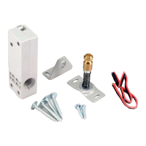
PROMIX
PROMIX Promix-SM420 User manual
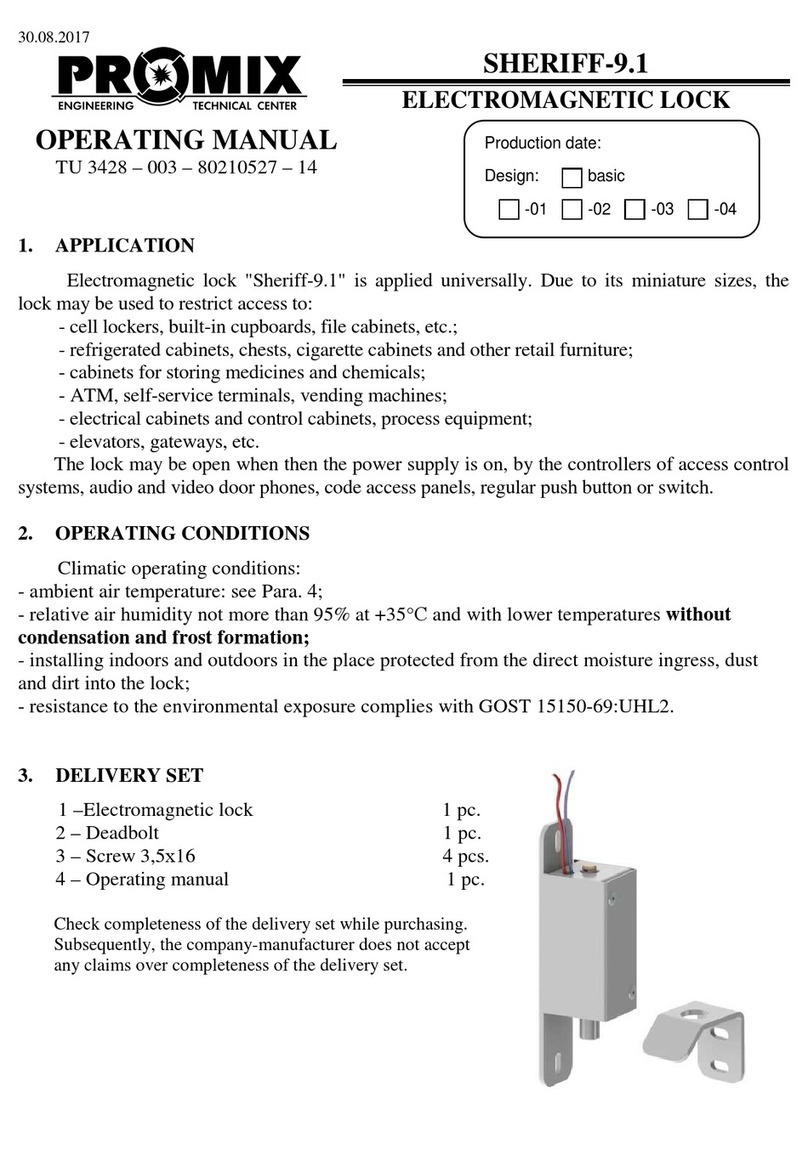
PROMIX
PROMIX SHERIFF-9.1 User manual
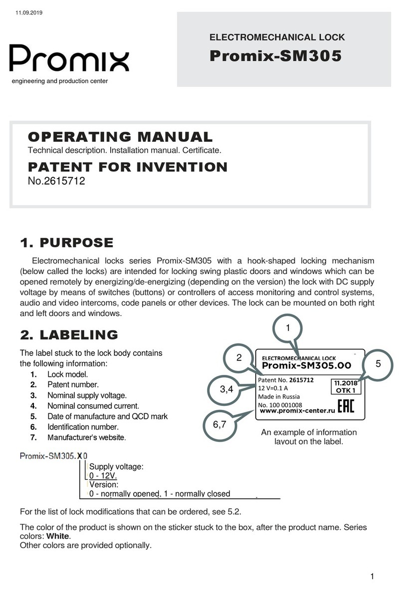
PROMIX
PROMIX SM305 User manual
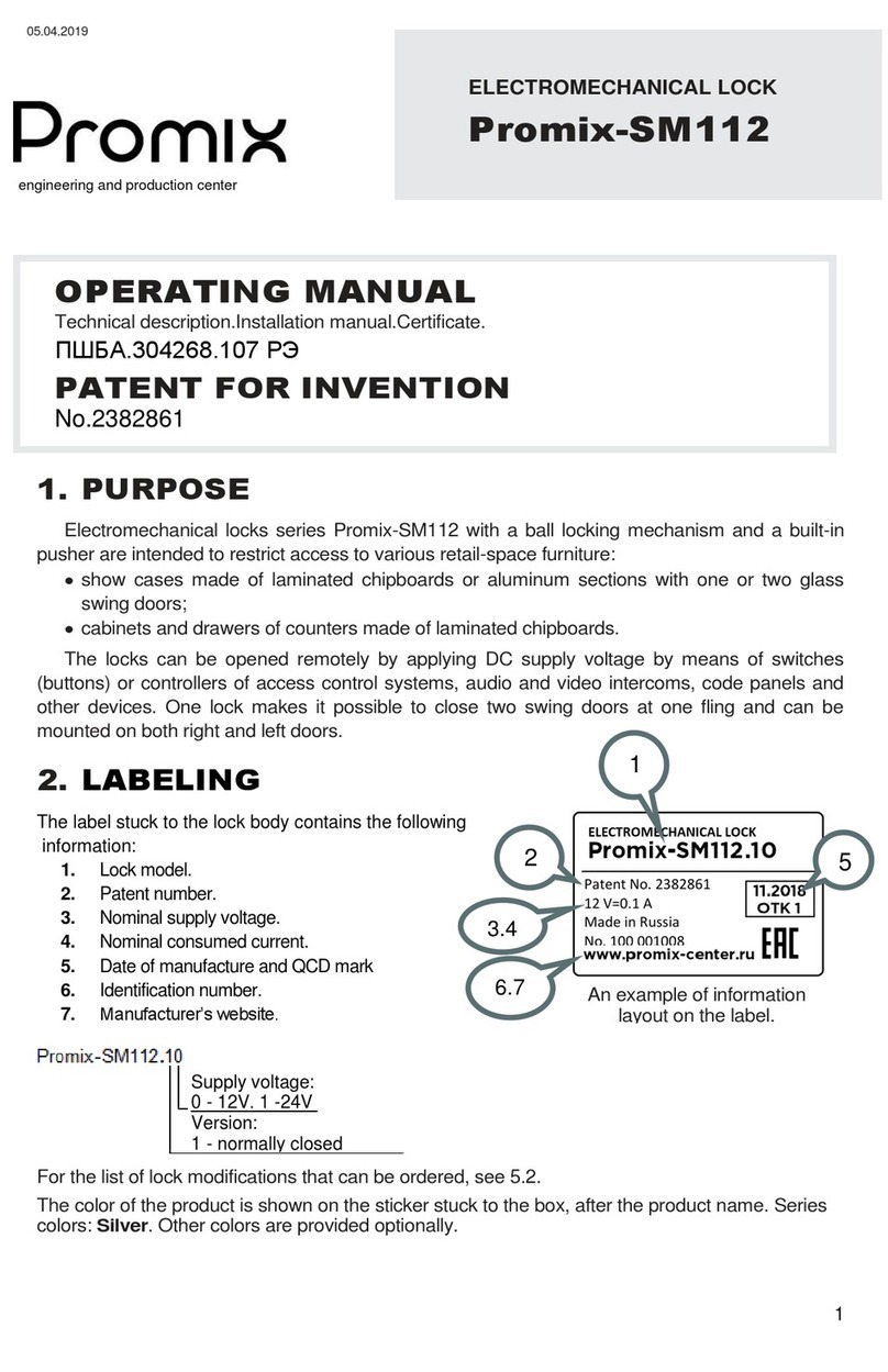
PROMIX
PROMIX Promix-SM112 Series User manual
Popular Lock manuals by other brands
CODELOCKS
CODELOCKS KL1050 Programming & operating manual
Motormate
Motormate Yamaha 10-301 installation instructions
AmazonBasics
AmazonBasics B07T5MMZ46 quick start guide

Ofs
Ofs carolina Mile Marker StealthLock instructions
Amazon
Amazon B07T5MMHXS quick start guide

Belwith
Belwith FIRST WATCH 1381 instructions
