Promotech PRO 5 PB User manual


Contents
1. GENERAL INFORMATION............................................................................................... 3
1.1. Application................................................................................................................. 3
1.2. Technical data............................................................................................................ 3
1.3. Equipment included ................................................................................................... 5
1.4. Design ....................................................................................................................... 6
2. SAFETY PRECAUTIONS.................................................................................................. 7
3. STARTUP AND OPERATION........................................................................................... 9
3.1. Installing the jaw blocks and tool bits ......................................................................... 9
3.2. Installing (removing) the mandrel and adjusting the clearance..................................10
3.3. Installing the motor....................................................................................................11
3.4. Clamping the machine into the pipe..........................................................................12
3.5. Preparing the air (for machine with air motor) ...........................................................13
3.6. Operating..................................................................................................................13
3.7. Troubleshooting the electric motor............................................................................15
3.8. Troubleshooting the cordless electric motor..............................................................15
3.9. Replacing the spindle disk ........................................................................................16
3.10. Facing and bevelling at the same time....................................................................17
4. ACCESSORIES...............................................................................................................18
4.1. Tool bits for carbon steel...........................................................................................18
4.2. Tool bits for stainless steel........................................................................................20
4.3. Cutting fluid...............................................................................................................21
4.4. Electric motor............................................................................................................21
4.5. Electric motor attachment set....................................................................................21
4.6. Air motor...................................................................................................................22
4.7. Air preparation unit....................................................................................................22
4.8. 75 mm spindle disk...................................................................................................22
4.9. 140 mm spindle disk set............................................................................................23
4.10. Ratchet wrench.......................................................................................................24
4.11. Small expanding mandrel........................................................................................25
4.12. Cordless electric motor............................................................................................25
4.13. Cordless electric motor attachment set ...................................................................26
4.14. 5.2 Ah battery..........................................................................................................26
4.15. Battery charger .......................................................................................................26
5. DECLARATIONS OF CONFORMITY...............................................................................27
6. QUALITY CERTIFICATE..................................................................................................30
7. WARRANTY CARD..........................................................................................................31

PRO 5 PB/PBE/PBC
This document is protected by copyrights.
Copying, using, or distributing without permission of PROMOTECH is prohibited.
3
1. GENERAL INFORMATION
1.1. Application
The PRO 5PB / PBE / PBC is apipe bevelling machine designed to mill edges of pipes
made of carbon and stainless steel, aluminum alloys, and copper-nickels. Depending
on the tool bit used, the machine can perform external bevelling, J-bevelling, internal
calibration, and facing pipes from inside diameters of 32 mm (1.26’’) to outside
diameters of 114 mm (4.49’’). Up to three tool bits can be installed at the same time.
When equipped with an optional 140 mm spindle disk set the machine can bevel
pipes with outside diameters up to 140 mm, and using an optional 75 mm spindle disk,
ratchet wrench, or both, will facilitate working in places hard to reach. An optional small
expanding mandrel will allow machining pipes with internal diameters from 25 mm to
33 mm (0.98–1.30’’).
1.2. Technical data
PRO 5 PB
PRO 5 PBE
PRO 5 PBC
Pressure
0.6 MPa (87 psi)
–
–
Voltage
–
1~ 110–120 V, 50–60 Hz
1~ 220–240 V, 50–60 Hz
18 V DC, 5.2 Ah
Air motor
Modec
NT10RT0851FCA1F-CO
–
–
Electric motor
–
Metabo BE1100
Metabo BS 18 LTX
Impuls
Connection
CEJN 410 DN 10.4
R 1/2’’ BSPT coupling
Electrical plug
Battery connection
Air consumption
1400 Nl/min (50 CFM)
–
–
Power
800 W
1100 W
–
Pipe diameter
32 mm ID to 114 mm
OD (1.26–4.49’’)
32 mm ID to 114 mm
OD (1.26–4.49’’)
32 mm ID to 114 mm
OD (1.26–4.49’’)
Maximum pipe
wall thickness for
outside diameter
up to 114mm
12 mm (0.47’’)
12 mm (0.47’’)
12 mm (0.47’’)
114–124mm*
10 mm (0.39’’)
10 mm (0.39’’)
10 mm (0.39’’)
124–132mm*
8 mm (0.31’’)
8 mm (0.31’’)
8 mm (0.31’’)
132–140mm*
6 mm (0.24’’)
6 mm (0.24’’)
6 mm (0.24’’)
Rotational speed without load
180 rpm
–
0–50 rpm (gear 1)
0–180 rpm (gear 2)
Nominal rotational speed
90 rpm
0–90 rpm (gear 1)
0–300 rpm (gear 2)
–
Protection class
–
II
–
Required ambient temperature
0–40°C (34–104°F)
0–40°C (34–104°F)
0–40°C (34–104°F)
Weight with motor
10 kg (22 lbs)
11 kg (24 lbs)
10 kg (22 lbs),
includes battery
* Available with the optional 140 mm spindle disk set.
PRO 5 PB/PBE/PBC
This document is protected by copyrights.
Copying, using, or distributing without permission of PROMOTECH is prohibited.
4
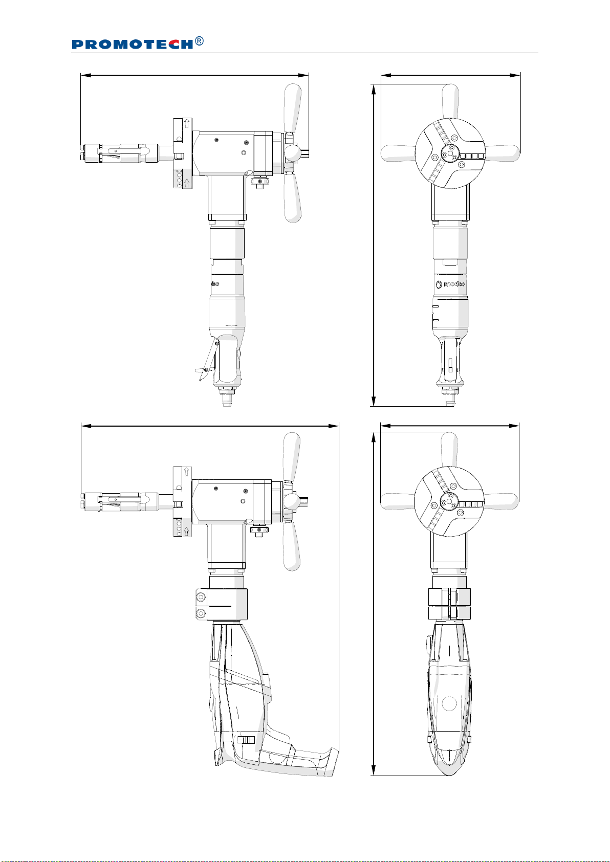
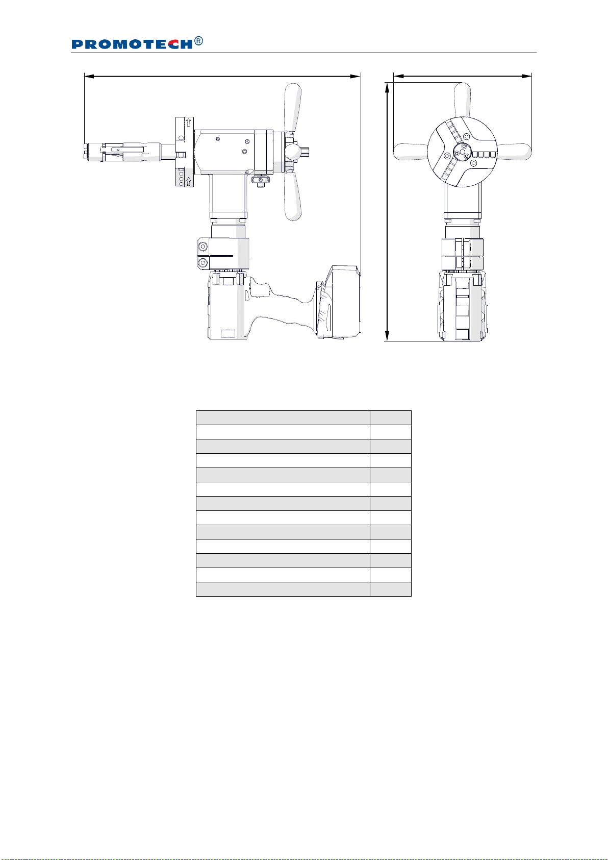
380 mm (15’’)
232 mm (9’’)
539 mm (21’’)
577 mm (23’’)
433 mm (17’’)
232 mm (9’’)
PRO 5 PB/PBE/PBC
This document is protected by copyrights.
Copying, using, or distributing without permission of PROMOTECH is prohibited.
5
1.3. Equipment included
The machine is supplied including the following elements.
Bevelling machine (without tool bits)
1 unit
Metal box
1 unit
Expanding mandrel
1 unit
118 mm spindle disk
1 unit
Jaw blocks (number 1, 2, 3, 4, 5, 6)
3 sets
Coolant container
1 unit
Tool container
1 unit
13 mm socket wrench
1 unit
6 mm hex wrench
1 unit
5 mm hex wrench
1 unit
4 mm hex wrench with handle
1 unit
3 mm hex wrench with ball end
1 unit
Operator’s Manual
1 unit
434 mm (17’’)
468 mm (18.4’’)
232 mm (9’’)

PRO 5 PB/PBE/PBC
This document is protected by copyrights.
Copying, using, or distributing without permission of PROMOTECH is prohibited.
6
1.4. Design
Fig. 1. View of PRO 5 PB and of PBE electric motor and PBC cordless electric motor
Spoke handle
Clearance
adjustment
unit
Expanding mandrel
Spindle disk
Air motor
ON/OFF lever
Air connection
Draw nut
Feed
indicator
ON switch lock
ON/OFF switch
Rotation direction switch
(must be set as shown)
Gear switch
Speed adjustment dial / LED
Rotation direction switch
(must be set as shown)
ON/OFF switch
with speed adjustment
Gear switch
Torque adjustment dial
Battery
LED activation button
LED

PRO 5 PB/PBE/PBC
This document is protected by copyrights.
Copying, using, or distributing without permission of PROMOTECH is prohibited.
7
2. SAFETY PRECAUTIONS
1. Before beginning, read this Operator’s Manual and complete proper occupational
safety and health training.
2. Use only the air (electric) motor specified in the technical data.
3. Use the machine only in applications specified in this Operator’s Manual.
4. The machine must be complete and all parts must be genuine and fully operational.
5. The specifications of the air (power) source must conform to those specified on the
rating plate.
6. Supply the machine with air motor only with clean and lubricated air. The air source
must be equipped with a filter, regulator, and lubricator.
7. Never pull the hose (cord) because this may damage it and result in serious injury.
8. Untrained bystanders must not be present near the machine.
9. Before beginning, check the condition of the machine, air (power) source, supply
hose (power cord, battery), coupling (plug), control components, and tool bits.
10. Avoid unintentional starts. Do not lay the machine so that the motor will start and
never carry the machine with air motor by using the ON/OFF lever.
11. Keep the machine dry and never expose it to rain, snow, or frost.
12. Keep the work area well lit, clean, and free of obstacles.
13. Neveruse machinenearflammable liquids orgases, or in explosive environments.
14. Secure the pipe to prevent it from falling or rolling.
15. Use only tool bits specified in this Operator’s Manual.
16. Never use tool bits that are dull or damaged.
17. Install tool bits securely. Remove adjusting keys and wrenches from the work
area before connecting the machine to the air (power) source.
18. Before every use, inspect the machine to ensure it is not damaged. Check whether
any part is cracked or improperly fitted. Make sure to maintain proper conditions
that may affect the operation of the machine.
19. Always use eye and hearing protection, protective footwear, and protective clothing
during operation. Do not wear loose clothing.
20. Operate the machine with an electric motor only when the rotation direction switch
is set to the position shown in Fig. 1. Using left rotation (rotation direction switch
set to the opposite position) may damage the machine.

PRO 5 PB/PBE/PBC
This document is protected by copyrights.
Copying, using, or distributing without permission of PROMOTECH is prohibited.
8
21. Do not touch moving parts or metal chips formed during milling. Prevent objects
from being caught in moving parts.
22. After every use, remove metal chips and excess coolant from the machine. Never
remove chips with bare hands. Clean the machine with a cotton cloth without
using any agents.
23. Cover steel parts with a thin anti-corrosion coating to protect the machine from
rust when not in use for any extended period.
24. Maintain the machine and install/remove parts and tool bits only when the machine
is unplugged from the air (power) source.
25. Repair only in a service center appointed by the seller.
26. If the machine falls from any height, is wet, or has any other damage that could
affect the technical state of the machine, stop the operation and immediately
send the machine to the service center for inspection and repair.
27. Never leave the machine unattended during operation.
28. Remove from the worksite and store in a secure and dry location when not in use,
previously removing the tool bits from sockets.

PRO 5 PB/PBE/PBC
This document is protected by copyrights.
Copying, using, or distributing without permission of PROMOTECH is prohibited.
9
3. STARTUP AND OPERATION
3.1. Installing the jaw blocks and tool bits
Use the following table to select jaw blocks suitable to the diameter of the pipe to be
machined.
Pipe inside diameter
Jaw blocks
number
[mm]
[inch]
32–43.5
1.26–1.71
–
43–55
1.69–2.17
1
54–66.2
2.13–2.61
2
64.7–76.9
2.55–3.03
3
74.9–87.1
2.95–3.43
4
85.2–97.4
3.35–3.83
5
94.8–107
3.73–4.21
6
Use the 3 mm hex wrench to join the jaw blocks to the expanding mandrel (1, Fig. 2).
Then, select up to three tool bits suitable to planned use, and place them in the
sockets, with blades directed according to the rotation direction 2. Next, tighten each
tool bit with two of the screws 3with the 4 mm hex wrench. The entire pressing
surface of the screw must be in full contact with the tool bit.
Fig. 2. Installing the jaw blocks and tool bits
1
2
3
PRO 5 PB/PBE/PBC
This document is protected by copyrights.
Copying, using, or distributing without permission of PROMOTECH is prohibited.
10
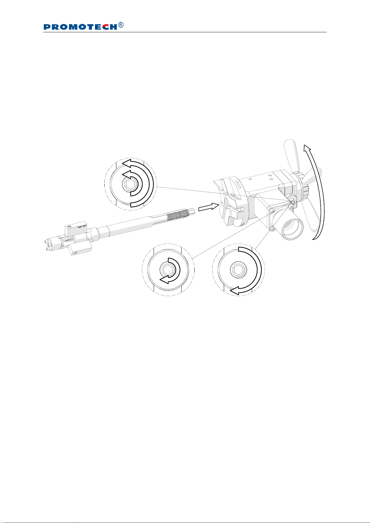
3.2. Installing (removing) the mandrel and adjusting the clearance
Loosen the nut and use the 6 mm hex wrench to loosen the set screw (1, Fig. 3), and
insert the mandrel into the machine (2). Make sure that tool bits installed are not in
contact with the mandrel. Next, rotate the spoke handles to the right (3) by at least 10
turns until the mandrel engages with the machine completely. Then, tighten the set
screw (4)and check whether the spoke handles can be rotated in both directions
easily. If the screw is too tight, readjust it. Finally, tighten the lock nut (5).
Fig. 3. Installing the mandrel into the machine
If the expanding mandrel becomes loose causing vibrations of the tool bits during
machining, perform the above actions without removing the mandrel from the machine.
To remove the mandrel, loosen the nut and use the 6 mm hex wrench to loosen
the set screw (1,Fig. 3) by at least one turn. Then, rotate the spoke handles to the left
to disengage the mandrel from the machine.
1
2
4
5
3
3
PRO 5 PB/PBE/PBC
This document is protected by copyrights.
Copying, using, or distributing without permission of PROMOTECH is prohibited.
11
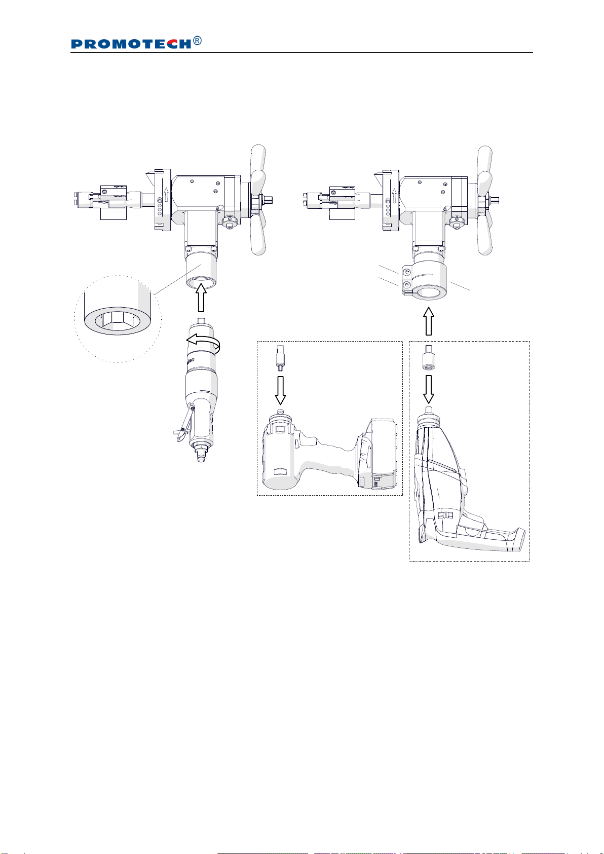
3.3. Installing the motor
Insert the air motor into the machine (1, Fig. 4a) so that the arbor is placed in the
socket 2, and tighten the motor by rotating it to the left (3).
Fig. 4. Installing the air motor (a) and an electric motor (b)
To install an electric motor, slide the clamping ring 4onto the machine. Then, screw
the driver (5) into the motor and insert the motor into the machine (6) by placing the
arbor in the socket 2, and tighten the clamping ring with the 6 mm hex wrench (7).
Finally, set the rotation direction switch to the position shown in Fig. 1.
1
2
3
a)
b)
5
5
6
7
5
4
5
5
PRO 5 PB/PBE/PBC
This document is protected by copyrights.
Copying, using, or distributing without permission of PROMOTECH is prohibited.
12
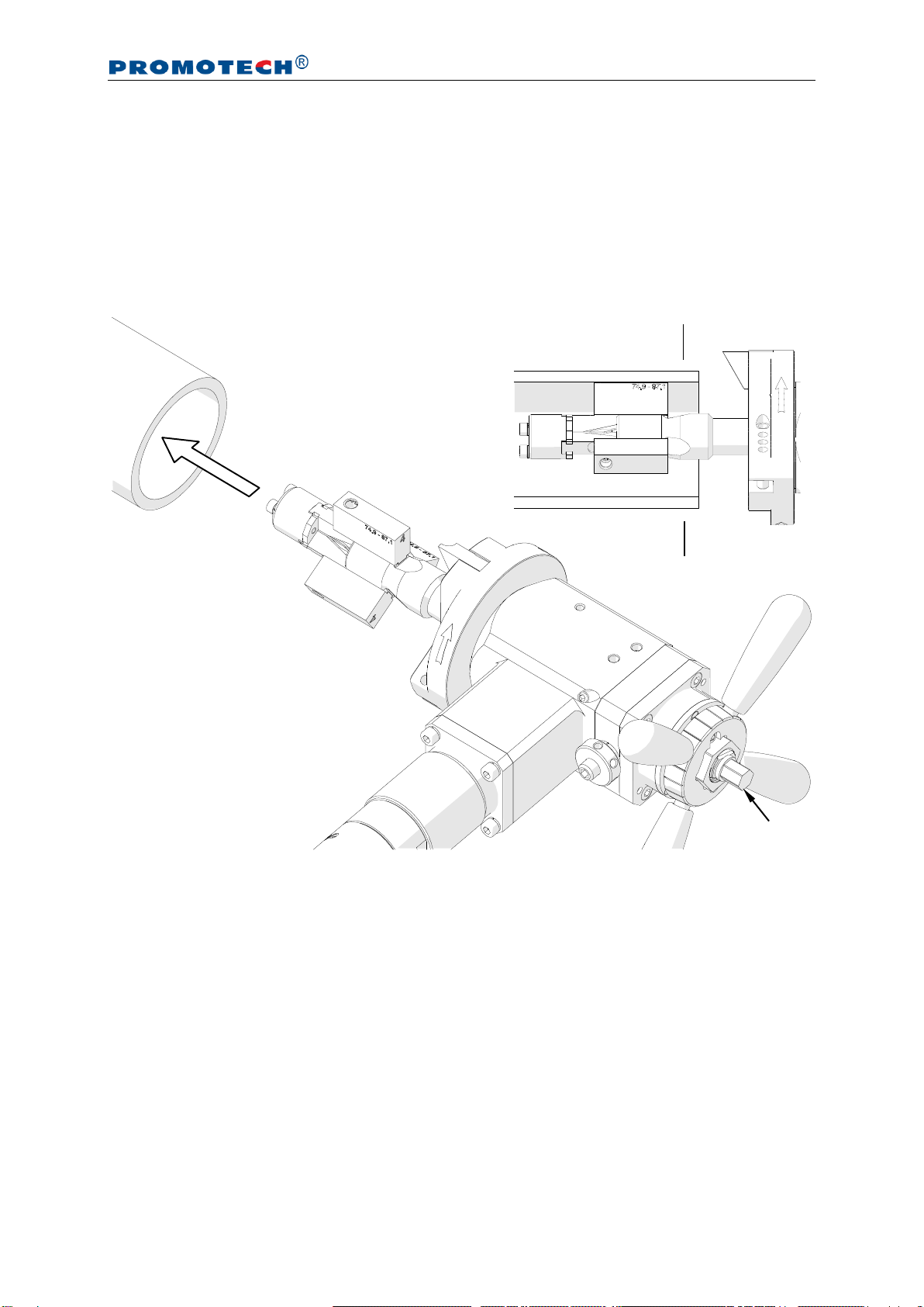
3.4. Clamping the machine into the pipe
Insert the assembled machine into the pipe (1, Fig. 5) so that the tool bit(s) is placed
at the distance of at least 3 mm (0.12’’) from the pipe end. Then, expand the jaw
blocks to the inside diameter of the pipe by rotating the draw nut 2to the right with
the 13 mm socket wrench. The jaw blocks must be installed beyond the end
preparation location 3.
Fig. 5. Clamping the machine into the pipe
2
1
3
3

PRO 5 PB/PBE/PBC
This document is protected by copyrights.
Copying, using, or distributing without permission of PROMOTECH is prohibited.
13
3.5. Preparing the air (for machine with air motor)
Connect the machine to a correctly prepared air source of sufficient purity by using
a hose with the internal diameter of at least 12 mm (0.5’’). The air source must be
equipped with an air preparation unit: filter, regulator, and lubricator (FRL). To achieve
full power of the air motor, all internal diameters of the air source must be at least
10 mm (0.4’’).
Maintain the FRL unit as required to keep the water trap drained, filter cleaned,
and the lubricator oil reservoir filled so that there is a drop of oil every 2–5 seconds.
Use only oil whose ignition temperature is more than 260°C (500°F). If the machine is
to be left idle for at least 24 hours after the work is finished, increase the delivery of oil
and run the motor for 2–3 seconds, which will prevent rusting and degrading of the
rotor vanes.
3.6. Operating
After the machine is connected to a proper supply, press the ON/OFF lever to start.
For the machine with an electric motor, set the gear 1 and, in cordless motor, the
maximum torque, and then press and hold the ON/OFF switch. To lock the switch in
the position ON (not available in cordless), press the ON switch lock before releasing
the ON/OFF switch. To adjust the speed, use a dial or, in cordless motor, change the
extent to which the ON/OFF switch is pressed.
Spread the coolant on the working edge. Then, bring the tool bit(s) close to the
pipe by rotating the spoke handles to the right. If the pipe face is not perpendicular to
the pipe axis, the tool bit will machine only a small segment of the pipe during initial
rotations. Thus, the feed rate should be chosen slow until the tool bit is contacting the
pipe continually during at least one rotation. The axial feed is 0.11 mm (0.004’’) per
graduation (Fig. 6) or 2 mm (0.08’’) per one complete turn of the spoke handles.
Fig. 6. View of the feed indicator
Feed direction
0.11 mm (0.004’’)

PRO 5 PB/PBE/PBC
This document is protected by copyrights.
Copying, using, or distributing without permission of PROMOTECH is prohibited.
14
Continue machining by rotating the spoke handles to the right. Use adequate feed
rate to establish a continuous chip cut. If the feed rate is too slow, only light stringer
chips will be removed, while too fast feed will make machining difficult and the chip
will start to have a rough or torn appearance. Never allow the tool bit to burnish the
surface. If chatter problems occur, reduce the feed rate and speed, and make sure
the type of tool bits corresponds to the material and the tool bits are sharp. Stainless
steel, which work hardens, must be worked with a fast enough feed, 0.08–0.15 mm
(0.003–0.006’’) per rotation, to stay under the work hardened surface.
If the machine with electric motor becomes overloaded, the motor will be shut off
automatically. However, prevent the motor from overloading and, if possible, machine
hardmaterials with not too fast feed rate and rotational speed.
After the pipe end is machined completely, discontinue rotating the spoke handles
and allow several more turns to improve the finish of the surface. Then, turn off the
motor by using the ON/OFF lever/switch, and wait until the rotation stops. Separate
the tool bit(s) from the pipe end to at least 3 mm (0.12’’) by rotating the spoke handles
to the left. Finally, loosen the draw nut with the 13 mm socket wrench to release the
clamping, and then remove the machine from the pipe. Use petroleum ether to clean
the pipe from excess coolant.
Clean the machine with a cotton cloth without using any agents.

PRO 5 PB/PBE/PBC
This document is protected by copyrights.
Copying, using, or distributing without permission of PROMOTECH is prohibited.
15
3.7. Troubleshooting the electric motor
The machine with electric motor has aLED for troubleshooting. The LED permanently
lit means that the machine power is limited to prevent the motor from overheating as
a result of continuous overloading for extended periods.
Rapid flashing means that the safety circuit prevents the machine from starting
automatically when electrical power is restored after a power failure. To start the
machine is such a case, switch the motor off and on again.
Slow flashing means that the carbon brushes are almost completely worn, which
results in the motor shutting off automatically. The brushes must be replaced with
new ones by the manufacturer of the electric motor.
3.8. Troubleshooting the cordless electric motor
The machine with cordless electric motor has aprotection system that automatically
shuts off the motor when it is continuously overloaded for extended periods. To stop
the beeping signal that sounds in such a case, release the ON/OFF switch. If the
motor or battery feels very warm, wait until it cools before proceeding.
The motor can also shut off automatically if the machine jams in the workpiece.
To continue operation, release the ON/OFF switch and press it again. Avoid repeated
jamming in the workpiece.
Flashing of the LED means that the battery is almost completely discharged.
To see the charge level, press the LED activation button and check the LED. If the
battery is discharged completely, charge the battery or replace to a fully charged.

PRO 5 PB/PBE/PBC
This document is protected by copyrights.
Copying, using, or distributing without permission of PROMOTECH is prohibited.
16
3.9. Replacing the spindle disk
Loosen the nut and use the 6 mm hex wrench to loosen the set screw (1, Fig. 7) by
at least one turn. Then, rotate the spoke handles to the left (2) to disengage the
mandrel from the machine (3).
Fig. 7. Removing the mandrel from the machine
Use the 5 mm hex wrench (1, Fig. 8) and remove the spindle disk (2). Then, install
the new disk (3) onto the pin 4 and tighten with the same screws.
Fig. 8. Replacing the spindle disk
1
2
3
1
2
3
4

PRO 5 PB/PBE/PBC
This document is protected by copyrights.
Copying, using, or distributing without permission of PROMOTECH is prohibited.
17
3.10. Facing and bevelling at the same time
When facing and bevelling is performed at the same time, use either short or long
bevelling tool bit depending on the pipe diameter (Fig. 9).
Fig. 9. Positioning the facing tool bit and a short or long bevelling tool bit
F0-30 facing tool bit
Short tool bit
Long tool bit
Short tool bit
Short or long
tool bit
Long tool bit
Long tool bit
Short or long
tool bit
Short tool bit
PRO 5 PB/PBE/PBC
This document is protected by copyrights.
Copying, using, or distributing without permission of PROMOTECH is prohibited.
18
4. ACCESSORIES
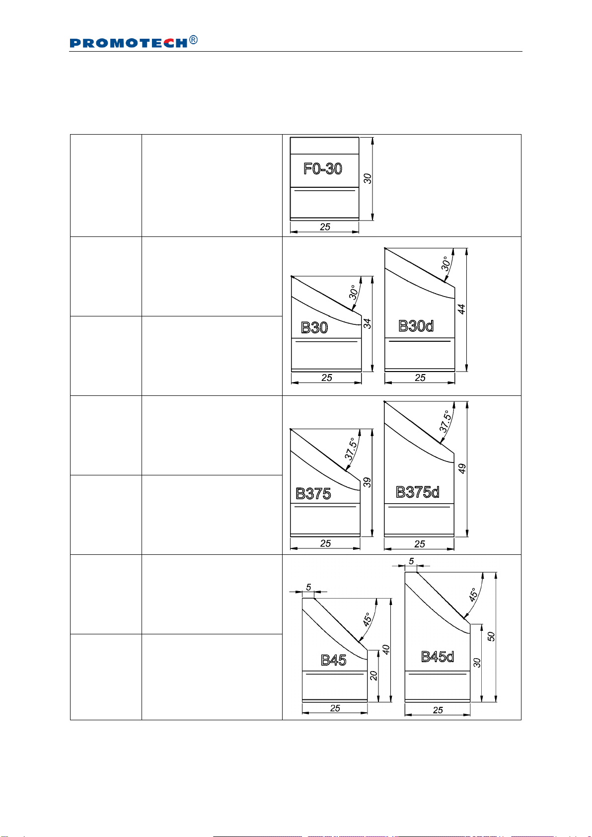
4.1. Tool bits for carbon steel
NOZ-000031
F0-30
0° facing tool bit
NOZ-000032
B30
30° bevelling tool bit*
NOZ-000033
B30d
30° bevelling tool bit**
NOZ-000036
B375
37.5° bevelling tool bit*
NOZ-000037
B375d
37.5° bevelling tool bit**
NOZ-000040
B45
45° bevelling tool bit*
NOZ-000041
B45d
45° bevelling tool bit**
* for diameters over 56 mm, if works together with 0°facing tool bit
** for diameters under 83 mm, if works together with 0°facing tool bit

PRO 5 PB/PBE/PBC
This document is protected by copyrights.
Copying, using, or distributing without permission of PROMOTECH is prohibited.
19
NOZ-000052
IC15-40 –on the left
15° internal calibration tool bit
NOZ-000053
IC15-40 –on the right
(for diameters over 56 mm)
15° internal calibration tool bit
NOZ-000058
J10-R6
10° J-bevelling tool bit
NOZ-000057
J15-R2
15° J-bevelling tool bit
NOZ-000059
J20-R8
20° J-bevelling tool bit

PRO 5 PB/PBE/PBC
This document is protected by copyrights.
Copying, using, or distributing without permission of PROMOTECH is prohibited.
20
4.2. Tool bits for stainless steel
NOZ-000067
F0-30
0° facing tool bit
(TiAlN coated)
NOZ-000034
NB30
30° bevelling tool bit*
(TiAlN coated)
NOZ-000035
NB30d
30° bevelling tool bit**
(TiAlN coated)
NOZ-000038
NB375
37.5° bevelling tool bit*
(TiAlN coated)
NOZ-000039
NB375d
37.5° bevelling tool bit**
(TiAlN coated)
* for diameters over 56 mm, if works together with 0°facing tool bit
** for diameters under 83 mm, if works together with 0°facing tool bit
This manual suits for next models
2
Table of contents
Other Promotech Industrial Equipment manuals


