Barco ISIS LFC User manual

ISIS LFC
Installation Guide

2______________________________________________________________ Barco – ISIS LFC – Installation Guide

Barco – ISIS LFC – Installation Guide ______________________________________________________________3
Contents
1. Introduction ...........................................................................................4
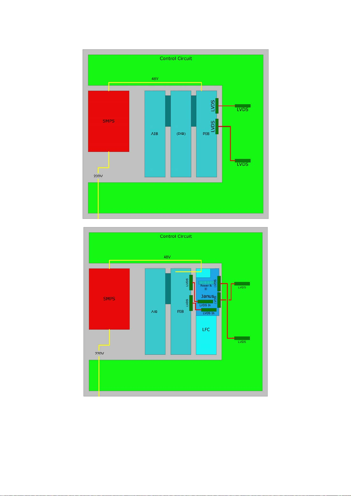
1.1 Product Description..........................................................................................4
1.2 System Requirements......................................................................................4
2. Installation.............................................................................................6
2.1 Introduction ...................................................................................................6
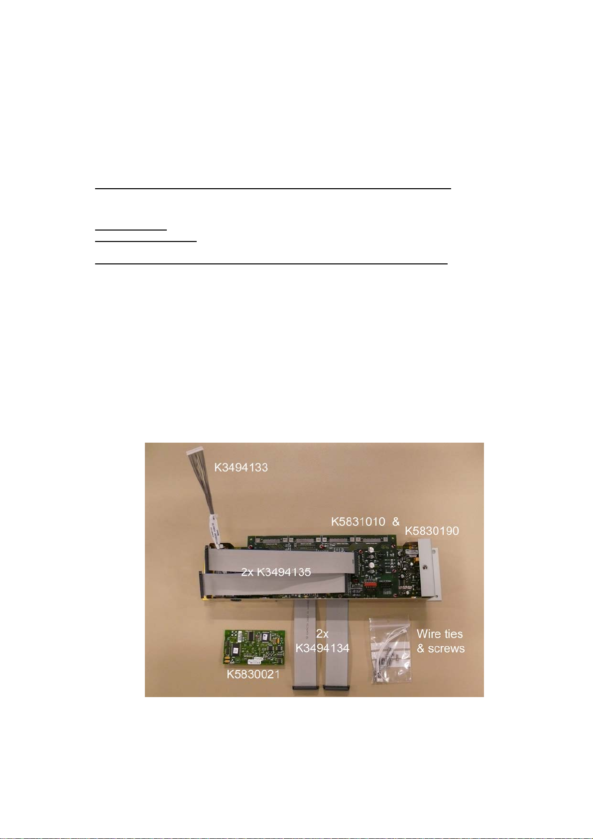
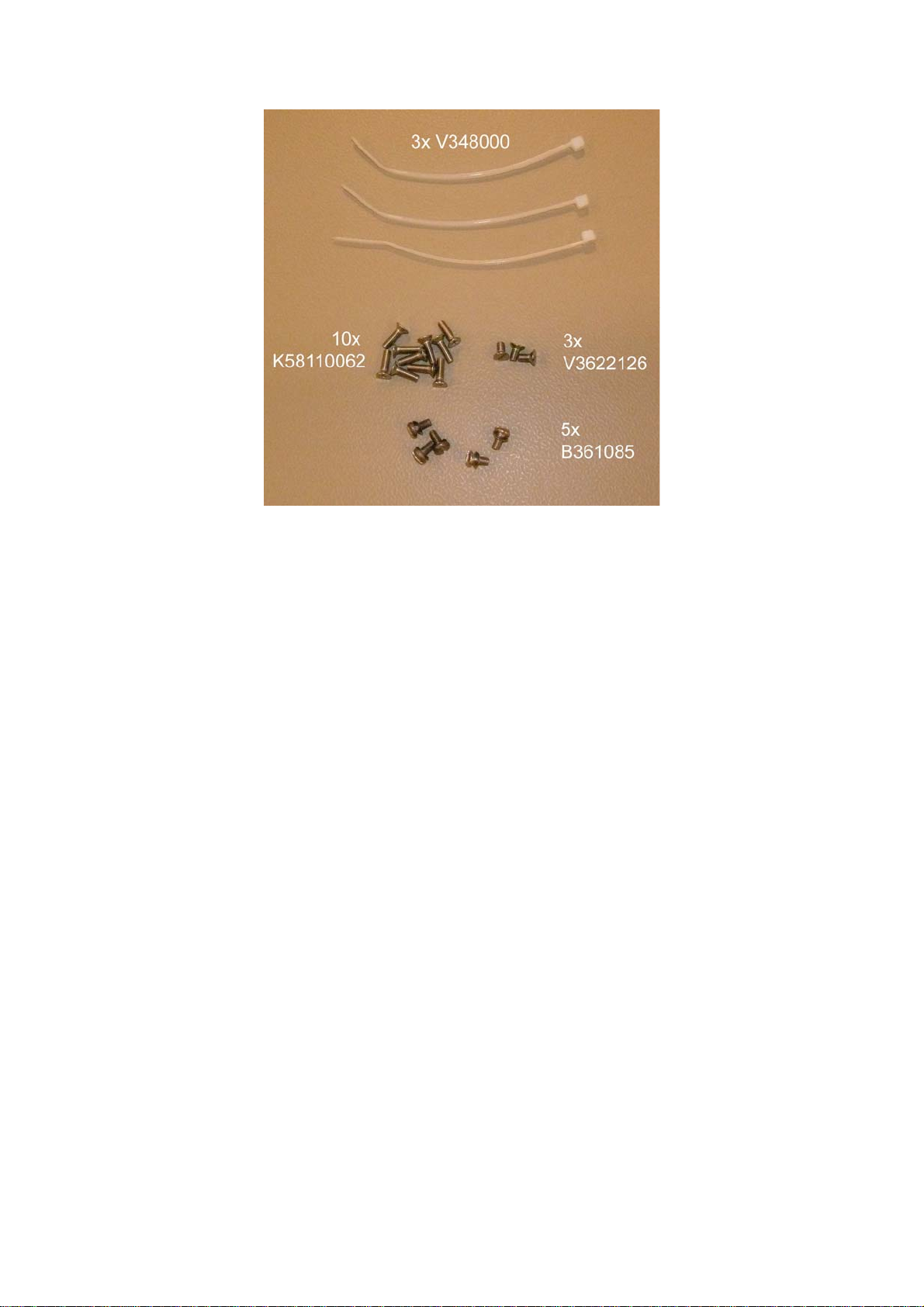
2.1.1 Parts list and figures...................................................................................6
2.1.2 Introduction..............................................................................................8
2.1.3 Tools required ...........................................................................................8
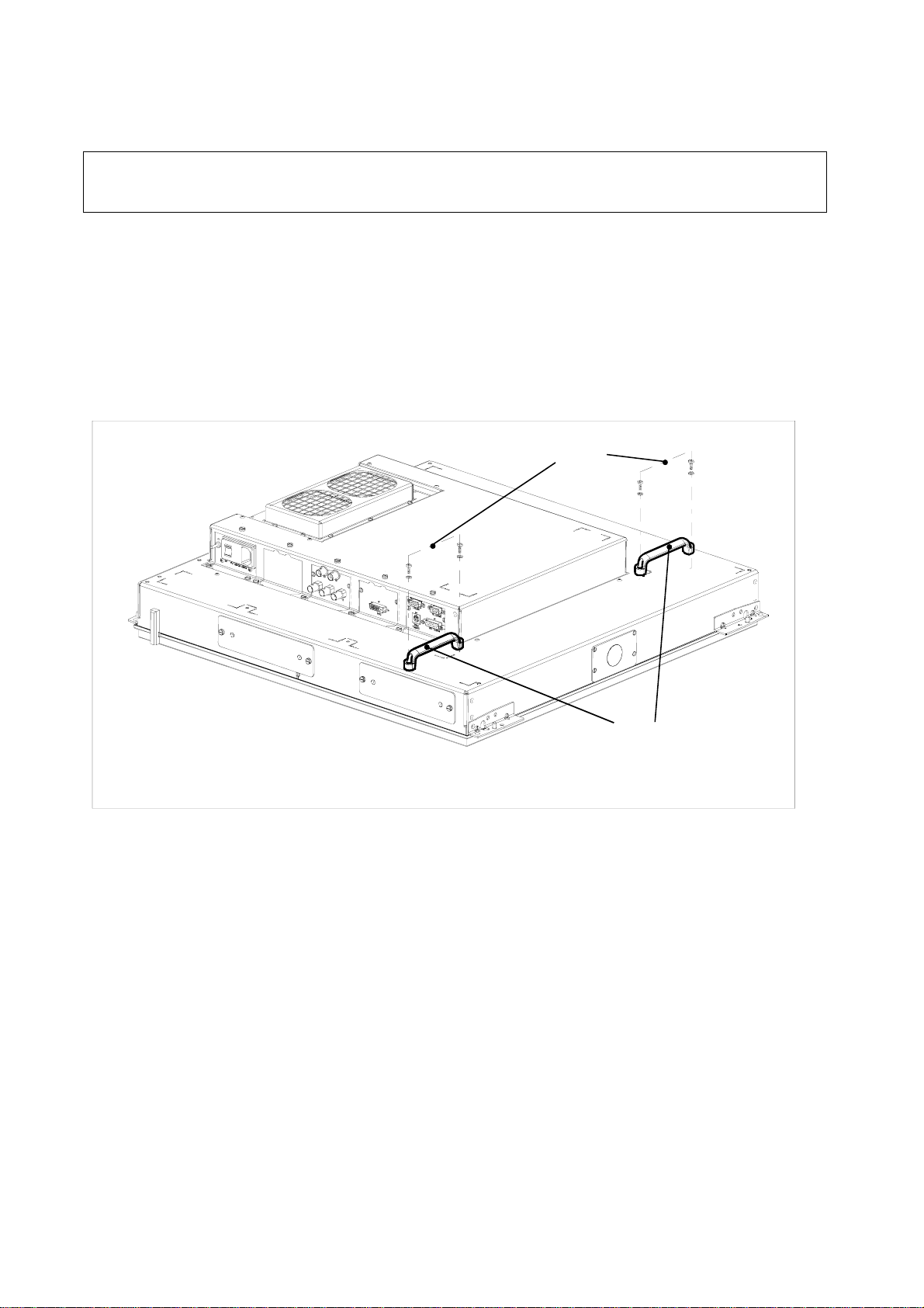
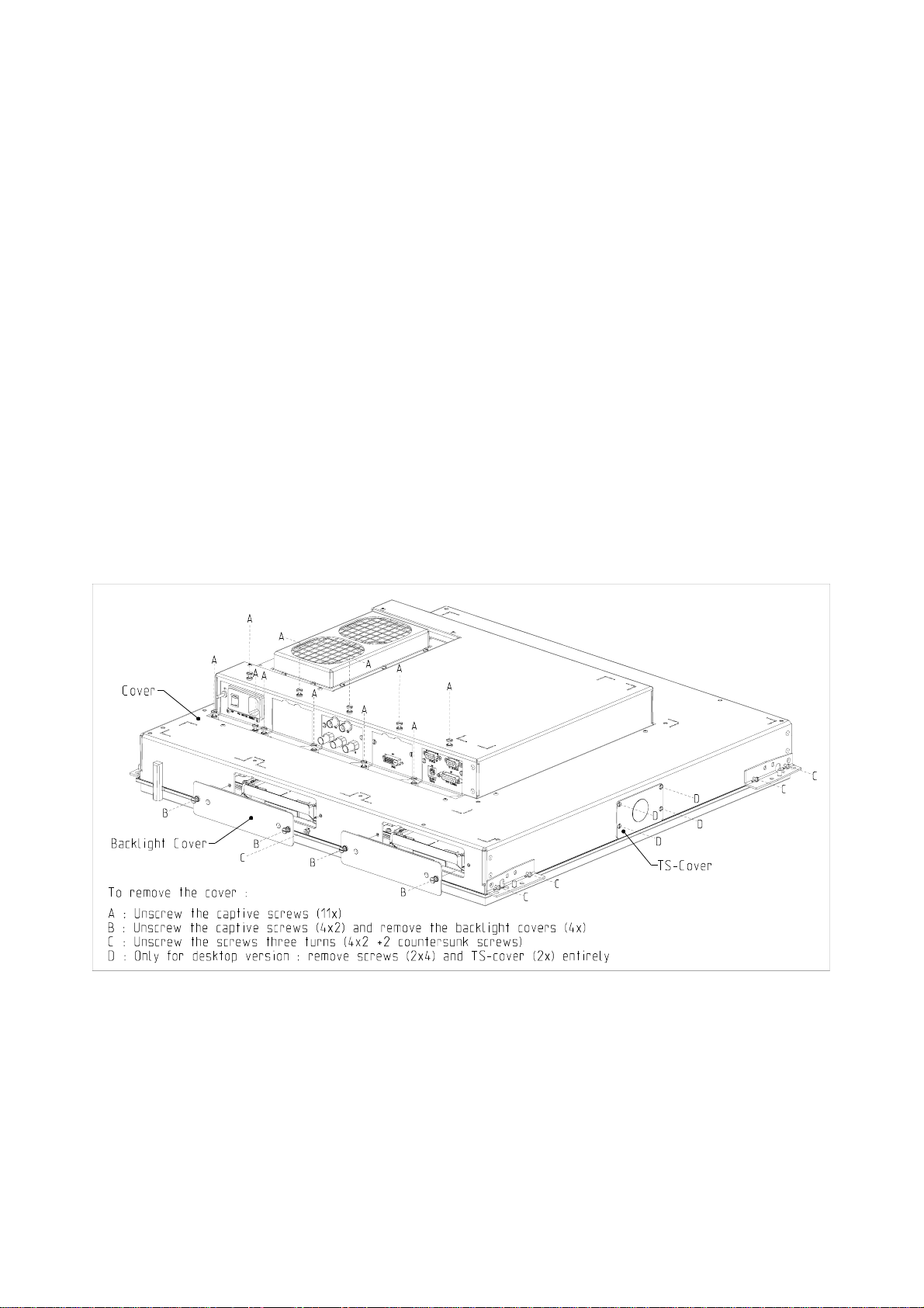
2.1.4 Removal of the rear cover...........................................................................9
2.1.5 Installation of modules and cables.............................................................. 10
2.2 Start-up and use........................................................................................... 14
2.2.1 Software upload ...................................................................................... 14
2.2.2 User Interface ......................................................................................... 14
2.2.3 LFC calibration......................................................................................... 20
Important Notices
The material in this guide consists of information that is the property of Barco and is intended
only for use by the purchasers of the type of product described in this guide.
The product contains material in which Barco retains proprietary rights. Any act involving
software reproduction or intervention is prohibited.
LFC (Light Flicker Compensation) is patent protected: CA2327429, EP0951007, NO316652,
KR10-0623622, SG76402, US6359663, US6909472.
THE TECHNICAL SPECIFICATIONS MENTIONED IN THIS GUIDE SHALL UNDER NO
CIRCUMSTANCES BE USED AS PROOF OR ITEM OF EVIDENCE.
ONLY THE TECHNICAL SPECIFICATIONS DEFINED IN THE BARCO TECHNICAL
SPECIFICATIONS DOCUMENT (WHICH IS NOT PART OF THIS GUIDE) CAN BE USED AS A
BASE FOR CONTRACT NEGOTIATIONS.
No parts of this guide may be reproduced in any form, by print, photocopy, microfilm or any
other means without written permission from Barco.
This guide could include inaccuracies or typographical errors. The guide is revised as often as
necessary to keep it as current and accurate as possible.
© Barco, September 2007

4______________________________________________________________ Barco – ISIS LFC – Installation Guide
1. Introduction
1.1 Product Description
When updating images with high contrast and high density (such as sonar or dense
information data) the LCD’s brightness varies with the rate of updating. This
luminance variation, referred to as ‘LCD Flicker’, can cause eye-fatigue and affect the
interpretation of the displayed data. With the ISIS LFC kit here described, a unique set
of algorithms is integrated in the ISIS display that reside in the hardware interface of
the display (between the graphics generator and the LCD). This feature compensates
for LCD Flicker without affecting the displayed data.
Figure 1-1 shows a preferred calibration set-up.
Figure 1-2 shows the differences between an ISIS display without and with LFC.
ISIS display
front side
LFC Board
OPTICAL
SENSOR
J39
J38
at display rear side
to J39
OPTICAL
SENSOR
to J10
KEYPAD
PIB board
OPTICAL SENSOR
J10
REMOTE IN
REMOTE AUX
J11
KEYPAD
PANEL
CONTROL
J40
J13
BARCO
KEYPAD
Figure 1-1 Preferred calibration set-up
1.2 System Requirements
Display software 2.04 or higher (already installed in the ISIS LFC kit modules).
Backlight trays (K5830120) with index 13 or higher.

Barco – ISIS LFC – Installation Guide ______________________________________________________________5
Figure 1-2 ISIS before and after LFC kit installation

6______________________________________________________________ Barco – ISIS LFC – Installation Guide
2. Installation
2.1 Introduction
In this section is described how to install an ISIS LFC kit into an ISIS type Main
Display Panel.
The installation must be performed by qualified personnel only.
2.1.1 Parts list and figures
Kit number: K5830195
Kit description: UN LFC INTEGRATION KIT ISIS
Part nr. Description Quantity
K5830190 G UN LFC POWER BOARD ISIS 1 (Mainboard)
K5831010 UN JANUS BOARD CATCH 1 (Mezzanine board)
K5830021 G UN MIC.PROCESSOR LFC ISIS 1
K3494133 CD MDMD 15AWG26P15 200 1 (cable)
K3494134 CD F0,63P50 FDOFDI HAL220 2 (cables)
K3494135 CD F0,63P50 FDOFDI HAL200 2 (cables)
B361085 SCR Z85 M 3 X 6 SS 5 (screws)
V3622126 SCR D963 M 3 X 6 SS 3 (screws)
K58110062 SCR D965 M 3 X 10 SS 10 (screws)
V348000 CBLA TIE B L100 W2,5 CLWH 3 (wire ties)
V606589 WARRANTY LABEL 200 1 (label)
Boards K5830190 and K5831010 and all cables can be supplied already mounted
together.
Figure 2-1 ISIS LFC kit parts

Barco – ISIS LFC – Installation Guide ______________________________________________________________7
Figure 2-2 Wire ties and screws
A new warranty label is added for attachment by a qualified person after installation
according to the installation procedure described herewith.

8______________________________________________________________ Barco – ISIS LFC – Installation Guide
2.1.2 Introduction
Do not loosen any screws unless they are mentioned in this installation procedure
Rear Cover removal is necessary before replacement of the electronic modules except for
backlight and fan replacements. The Rear Cover protects and hides the display electronics for
safe handling. The Rear Cover also provides a means of fixation for mounting the display.
Four removable Backlight Cover plates at the top and bottom close the holes through which
the Removable Backlights slide. Two removable cover plates (TS-Covers) at the left and right
sides hide two Pivot feed-through holes.
For a safe handling of the display, it is strongly recommended to mount, at least temporary,
two handles as shown on the figure hereby.
Figure 2-3 Safe MDP 471 Handling
Before starting the removal/reinstallation procedure of modules and/or boards,
place the unit on an ESD safe table with the front facing downwards.
2.1.3 Tools required
1 Slotted 4.5 mm or 3/16" screwdriver.
1 Phillips #1 screwdriver.
1 Opti-sense (V5660792) for calibration
1 Barco Keypad
Firmware Download Tool and KP/Upload cable Z3498894 or equivalent (ref. description of LFC
install).
For a safe handling of the MDP 471,
it is strongly recommended to mount, at least temporary,
two handles as shown on the figure hereby.
Parts list:
2 handles R724301 FRM DLITE TILE HDL
4 screws R362153 SCR D7985 M 4 X 12 STZN
4 washers R367378 SPR D125A D 4,3D 9 STZN
SAFE MDP 471 HANDLING
MDP471UM03ADD20020128
2 x R724301
4 x
R362153
&
R367378

Barco – ISIS LFC – Installation Guide ______________________________________________________________9
2.1.4 Removal of the rear cover
WARNING:
Once the warranty label is removed, the warranty will be voided.
A new warranty label is available in the kit which can be attached after installation
by a qualified person according to the installation procedure described hereafter.
Refer to Figure 2-4 MDP 471 Rear Cover removal.
• Loosen the 11 captive screws A; captive screws do not need to be completely removed.
• Unscrew the 4x2 captive screws B and remove the Backlight Covers (4x).
• Unscrew the 4x2 screws C (+2 countersunk screws) when present.
• Unscrew the 2x4 screws D when a TS-Cover is present (Desktop version only).
• Carefully lift up and flip over the rear cover.
Do not remove the Rear Cover completely and be careful of the connector cables between
the Rear Cover and the Backplane. The Backplane is the back of the LCD panel and
backlights including the attached interconnected electric boards. Carefully put the Rear
Cover beside the backplane of the LCD.
• To completely disconnect the Rear Cover when needed, disconnect the PIB (Panel
Interface Board) connector J7 from the Fan Module.
Figure 2-4 MDP 471 Rear Cover removal
.

10_____________________________________________________________ Barco – ISIS LFC – Installation Guide
2.1.5 Installation of modules and cables
2.1.5.1 Boards removal
From the PIB (Panel Interface Board K5830011), cut the two wire ties holding the
yellow power cable, disconnect the said power cable (with J1) and guide it through the
hole with bushing in the board’s metal support plate. See Figure 2-5 PIB power cord
removal.
1Wire tie V348000 to be cut
1
1
Figure 2-5 PIB power cord removal
Remove the AIB (Analog Input Board) K5830040 and the PIB (Panel Interface Board)
K5830011.
Remove the decorative dummy cover plate – if any - at the empty slot (Slot2) next to
where the AIB was mounted.
On the PIB (K5830011), replace the µprocessor board (K5830020) by a µprocessor
board (K5830021) and fix this with 2 screws B361085.
Lock 2 the screws with a threadlocker, by preference Loctite 242 (Barco ref.
V395121), and a tamperproofing coating, by preference Loctite 7400 Varnistop (Barco
ref. R395213).

Barco – ISIS LFC – Installation Guide _____________________________________________________________11
2.1.5.2 Boards installation
Install the LFC Board (two boards mounted together, Mainboard K5830190 and JANUS
mezzanine board K5831010) where was before a PIB (Panel Interface Board)
K5830011. See figure below.
Use a screw V3622126 at the decorative front plate side and a screw B361085 at the
other side of the LFC Board.
InputBoard
Fan 2
Fan 1
PIB
LFCBoard
Slot2
Slot1
OPTICAL
SENSOR
J39
J38
Figure 2-6 Board location with LFC
With reference to Figure 2-7 Panel CN1 and CN2 connection, connect a cable K3494134
between CN1 on the panel control circuit and J5 on the JANUS Board K5831010.
Connect a cable K3494134 between CN2 on the panel control circuit and J4 on the
JANUS Board K5831010.
Figure 2-7 Panel CN1 and CN2 connection

12_____________________________________________________________ Barco – ISIS LFC – Installation Guide
With reference to Figure 2-8 LFC Board installation and wiring, install the PIB K5830011 in
the slot next tot the LFC Board, but wait fixing it until the following cabling is made.
Connect a cable K3494135 between J11 on the JANUS Board K5831010 and J15 on
the PIB K5830011 board. Connect a cable K3494135 between J9 on the JANUS Board
K5831010 and J16 on the PIB K5830011 board.
Figure 2-8 LFC Board installation and wiring
Fix the PIB K5830011 at the decorative cover plate side with a screw V3622126 and at
the other side with a screw B361085.
With reference to Figure 2-9 , connect the yellow power cable (Z3421999) with J1 on
the PIB (K5830011). Connect the cable K3494133 between J6 of the LFC Board
K5830190 with J9 on the PIB K5830011, guiding the cable through the hole in the LFC
board metal support plate.
With reference to Figure 2-10 Cable fixation, fix the cables Z3421999 and K3494133
with 3 wire ties V348000.
Install the AIB K5830040 next to the PIB K5830011 and fix it at the decorative cover
plate side with a screw V3622126 and at the other side with a screw B361085.
With reference to Figure 2-4 MDP 471 Rear Cover removal, reinstall the rear cover not
forgetting to reconnect the Fan module. Use the 11 screws named “A”.
Use 10 new screws K58110062 for screwing the fixations named “C”.
Fix the 4 backlight covers with the 8 captive screws named “B”.
If done by qualified personnel and according to this installation procedure, a
new warranty label can be attached.

Barco – ISIS LFC – Installation Guide _____________________________________________________________13
1hole in LFC Board
1
support plate
Figure 2-9 PIB connection
1Wire tie V348000
1
1
1
Figure 2-10 Cable fixation

14_____________________________________________________________ Barco – ISIS LFC – Installation Guide
2.2 Start-up and use
2.2.1Software upload
Although software upload is described here below, it is not necessary when
installing a kit as the software is already loaded in it.
1. Connect the remote port (J11) with a null-modem cable to the COM port of your PC.
Note that the upload won’t work via the Keypad port!
2. Start up softloader and configure the terminal settings for 115200 baud, no parity and
the upload settings for 115200 baud, binary mode and auto connect disabled.
3. Using keypad or OSD, navigate to the LFC advanced menu. This is a submenu of the
Input Boards menu which is a submenu of the Administrator menu (UNIF button
on the keypad). See Advanced LFC menu (Administrator Menus) for more details. On
the last page of the LFC advanced menu select Upload: to start the upload.
The keypad/OSD should say Starting… and on the terminal the following text should
appear:
Sending signature
Waiting for INTEL HEX data record …
4. When Waiting for INTEL HEX data record has appeared or when the keypad (or OSD)
says 0 lines received the upload can be started. In softloader push the Upload button
and select the new .hex file to start the upload.
When the communication with the LFC hardware could not be established the upload
fails. In that case Upload failed is shown on keypad/OSD.
5. The keypad/OSD should now display how many lines there were received.
6. After the upload of data is done the data is programmed into the flash, indicated as
Programming flash … on the keypad/OSD.
7. When the programming is done the keypad/OSD will show Upload finished when the
programming was successful and Upload failed when the programming failed. This will
also be printed on the terminal in softloader.
2.2.2User Interface
LFC has to be “installed” before it can be used. See “LFC Install” further.
2.2.2.1 Enabling/disabling LFC (Administrator Menus)
LFC can be enabled in the Input Boards submenu of the Administrator menu of
either keypad or OSD menus. The keypad menu looks like this:
Input Submenu
InputSel:AUTO T
LFC:Disable T
LFC advanced..E
>
Input Priority <
High :Board 2T
Medium:Board 1T
Low :Board 3T>
No Sync Check <
Board 1:Off T
Board 2:Off T
Board 3:Off T

Barco – ISIS LFC – Installation Guide _____________________________________________________________15
Note that the LFC: Enable/Disable item and the LFC advanced submenu are only
available when LFC was installed (see “LFC install”).
2.2.2.2 Advanced LFC menu (Administrator Menus)
This is a submenu in the Input Boards menu (see “Enabling/Disabling LFC
(Administrator Menus)) and is focused at the calibration of LFC.
The layout in the keypad:
LFC advanced
Submenu
LFC tables
Table:Extern T
Invalid
FW. ver.: 0>
LFC Calibration<
Start: E
Status:
>
LFC Calibration<
Upload: E
Table Selects the calibration table to use, there are three possibilities.
0: External,
1: Internal 1,
2: Internal 2.
External uses the calibration table as stored in flash. This table is the
result of an external calibration. Internal 1 & 2 use a calibration table as
stored in the Panel EEPROM and are the result of an internal calibration.
Internal 2 is the result of last internal calibration. Internal 1 the one
before that.
FW. Ver. Stands for firmware version.
It contains the version of the LFC firmware (the version of the FPGA code
in the Janus).
The second page is dedicated to the (Internal LFC calibration):
Start Starts/stops the calibration
Status Indicates the progress.
See “LFC calibration” for more details.
The last page controls the upload of the LFC calibration software via the serial port of
the ISIS. see
Start Starts/stops the upload
The progress is indicated on the page
See “LFC calibration software upload” for more details.

16_____________________________________________________________ Barco – ISIS LFC – Installation Guide
2.2.2.3 LFC install
In order to be able to use LFC, LFC should be ‘installed’ first.
The following “LFC install” procedure should be carried out with utmost
precision. Entering a wrong command may render the display unserviceable
and requires a factory return.
Items needed:
•Firmware Download Tool (FDT) software;
•a KP/Upload cable Z3498894 or equivalent;
•a PC.
The needed items are included in the Barco ISIS Service Kit K5030070.
The Z3498894 cable pinning is also described here below.
1. Connect the COM port of the PC directly with the REMOTE IN (J11) PIB connector with
a 3-wire crossed KP/Upload cable Z3498894.This special cable is defined as follows.
Only pins 2, 3 and 5 are used. Pin 2 and 3 are twisted.
PC (SUBD9 – Male) ISIS (SUBD9 – Female)
2 3
3 2
5 5
2. Install and start on the PC the “Firmware Download Tool” and select “Barco
protocol”. Click “Next”.

Barco – ISIS LFC – Installation Guide _____________________________________________________________17
3. Select the COM-port connected to the ISIS REMOTE IN (J11) PIB connector and click
“Next”.
4. The software automatically tries to detect a Barco Protocol device – “Searching for BP
device...” is displayed in the terminal window. This takes a couple of seconds.
When the Barco Protocol device is found, following message is displayed:
“BARCO Protocol session opened successfully (COM1, baud rate 115200, ID 1)
Changing inactivity timeout to infinite
Error code 1: invalid command”

18_____________________________________________________________ Barco – ISIS LFC – Installation Guide
Verify if the software version of the ISIS is between V2.04 and V2.08 by typing “VE” in
the input field and click “Send”.
The terminal returns the command send and the answer from the ISIS display:
…“VE
…Received data: V2.08”
Remark: Barco protocol commands are case sensitive: e.g. if the command “ve”
instead of “VE” is sent, the display responds with:
“ve
Error code 1 : invalid command”
Important: Do not continue if the software version doesn’t match one of the
following versions: V2.04, V2.05, V2.06, V2.07 or V2.08.
Contact Barco for instructions if you have a different software version.
5. Enter WITH UTMOST PRECISION the following command in the input field:
@SETV,621,1
Entering a wrong command may render the display unserviceable and
requires a factory return.
Click “Send”.
The terminal returns following message:
“@SETV,621,1
Acknowledge”
Click “Disconnect” and “Finish” to end.
The terminal returns following message:
“Barco Protocol session closed successfully”

Barco – ISIS LFC – Installation Guide _____________________________________________________________19
This ends the “LFC Install” procedure.
When LFC is installed:
•The Janus board is configured on start-up when the Janus board was detected.
•LFC will be enabled on start-up (when it was enabled before).
•The LFC enabled/disabled item will be available in keypad & OSD menu’s (see
“Enabling/Disabling LFC” (Administrator Menus))
•A Fault will be generated (and indicated) when the Janus board was not
detected.
•A Warning will be generated (and indicated) when the flash does not contain
valid LFC calibration data.

20_____________________________________________________________ Barco – ISIS LFC – Installation Guide
2.2.3LFC calibration
2.2.3.1 Connections
Connect a Barco Keypad to connector J10, labelled “KEYPAD”, on the rear side of the
display.
Place the Optical Sensor on the front of the display and connect it to connector J40,
labelled “OPTICAL SENSOR” on the rear side of the display.
For best results, the calibration should be done at the display’s normal operating
temperature and with an input signal with scan rate specifications as normally used.
2.2.3.2 Calibration
Using the keypad, navigate to the LFC advanced Submenu:
1. Press the UNIF button on the keypad to go to the Administrator Menu.
Note: The administrator password is required before entering the Administrator Menu.
The password (9090) must be entered via the first line of the menu under the MISC2
button:
2. In the Administrator Menu go to the second line of the second page and hit enter on
Input Boards to open the Input Boards Submenu.
3. In the Input Boards Submenu hit ENTER on the third line, called LFC advanced.. to go
to the LFC advanced Submenu.
4. Finally LFC calibration is located on the second page of this LFC advanced Submenu.
Go to this page.
LFC calibration page on the keypad:
LFC Calibration<
Start: E
Status:
>
Table of contents
Other Barco Industrial Equipment manuals