Propex Pyramat Series Instruction Manual

Propex Operating Company, LLC - 4019 Industry Drive, Chattanooga, TN 37416 - p 800 621 1273 - www.propexglobal.com
PYRAMAT®SLOPE INSTALLATION
AND MAINTENANCE GUIDELINES
Thank you for purchasing our PYRAMAT®High Performance Turf Reinforcement Mat (HPTRM) or Turf Reinforcement Mat
(TRM) by Propex Operating Company, LLC (Propex). This document provides installation and maintenance guidelines for
PYRAMAT used as slope armoring to increase earthen slope resiliency. PYRAMAT provides permanent erosion protection
on either the flood side and/ or protected side of an earthen slope.
Temporary securing pins (pins) are used during installation to hold PYRAMAT in place. Pins also promote vegetation
establishment keeping PYRAMAT in intimate contact with the soil.
PYRAMAT is an Engineered Earth Armoring Solution TM with a unique design for each specific project. While Propex has
made every effort to ensure general validity, this information should not be used for a specific application without
independent professional examination and verification of its suitability, applicability, and accuracy. The information
provided herein is for general information only, and is intended to present installation guidance. Project specific contract
documents take precedence when pin placements are different than what is represented in this document. Depending
upon the critical nature of the structure to be armored, work restrictions may be in place such as limiting work based on
growing seasons, weather patterns, etc. Work should be performed under the provisions set forth for the specific project.
Propex Engineering Services is available for support during installation to consult for solving constructability issues
encountered in specific applications. Please feel free to call our techincal support hotline at (800) 621-1273.
BEFORE INSTALLATION BEGINS
Coordinate with a Propex Representative: A pre-construction meeting is suggested with the construction team and a
representative from Propex. This meeting should be scheduled by the contractor with at least a two week notice.
Gather the Tools Needed: Tools that you will need to install PYRAMAT include a pair of industrial shears to cut
PYRAMAT, tape measure, and mallet or hammer.
Determine how to Establish Vegetation: The method of vegetation establishment should be determined prior to the
start of installation. Different vegetation establishment methods require different orders of installation. Refer to
VEGETATION ESTABLISHMENT for further guidance.
INSTALLATION OF PYRAMAT ON SLOPES
SITE PREPARATION
It is recommended during all stages of site preparation that disturbed soils remain unprotected for not more than a
single day. Depending on project size this may require progressive site preparation during installation.
1. Grade and compact the area on the slope where PYRAMAT will be installed. The slope surface should be uniform
and smooth, having all rocks, clods, vegetation or other objects removed so that during PYRAMAT LAYDOWN,
PYRAMAT comes in direct, intimate contact with the slope surface.
2. Prepare the area to be armored with PYRAMAT by loosening the topsoil to promote better vegetation establishment.
This may be accomplished with a rotary tiller on slopes 3:1 or flatter. For slopes greater than 3:1, prepare topsoil in a
safe manner.
3. Excavate a Crest of Slope (COS) trench 12 in x 12 in (300 mm x 300 mm) minimum at a distance of 3 ft (900 mm)
from the crest of the slope. (Figure 1).

Page 2of 11
Propex Operating Company, LLC - 4019 Industry Drive, Chattanooga, TN 37416 - p 800 621 1273 - www.propexglobal.com
Figure 1: Crest of Slope (COS) Trench
4. Excavate a Toe of Slope (TOS) trench 12 in x 12 in (300 mm x 300 mm) minimum at a minimum distance of 5 ft (1.5
m) from the toe of the slope. (Figure 2)
5. If seeding, refer to VEGETATION ESTABLISHMENT for additional considerations during site preparation.
Figure 2: Toe of Slope (TOS) Trench
PYRAMAT LAYDOWN
1. Begin the PYRAMAT LAYDOWN process by starting with the downstream / downwind end of the site. To ensure
proper pining of the overlapped areas the proceeding roll width must be laid out before the current roll width can be
pinned with exception to the final roll width. For straight sections of a slope, PYRAMAT panel lengths should be long
enough to construct COS and TOS trenches while also covering the surface of the slope being armored (Figure 12).
Panel edges should rest approximately perpendicular to the slope center line. For best results, panels of PYRAMAT
should be continuous and free from seams or roll end overlaps that are parallel to the centerline of the slope. Panel
edge overlapping should follow a pattern of placing each proceeding panel’s edge overtop the previous panel edge,
shingling the panels in the direction of the water flow or prevailing wind.
2. Starting at the COS trench, lay PYRAMAT roll so that the roll ends point towards the crest of the slope (Figure 3), with
a 3 in (75 mm) overlap created at adjacent panel edge locations. Ensure that adjacent panel edges maintain a
minimum 3 in overlap during PYRAMAT LAYDOWN (Figure 8).

Page 3of 11
Propex Operating Company, LLC - 4019 Industry Drive, Chattanooga, TN 37416 - p 800 621 1273 - www.propexglobal.com
Figure 3: Crest of Slope (COS) Trench Alignment
3. Secure PYRAMAT with pins in the COS trench. Pins should be made of steel with a 0.20 in (5 mm)
minimum diameter, having a 1.5 in (38mm) diameter washer at the head, and a length between 12 and
24 in (300-600 mm) with sufficient ground penetration to resist pullout (Figure 4). Longer pins may be
required for looser soils. Heaver metal stakes may be required in rocky soils. Suggested placement of pins
for the COS trench is along the bottom of the trench with pins on 12 in (300 mm) centers. Pins should
also be installed on panel edge overlaps in the COS trench.
Figure 4: Securing Pin
4. Backfill and compact the COS trench in the location of the first PYRAMAT panel only (Figure 5).
Figure 5: Crest of Slope (COS) Trench Placement
5. Unroll the PYRAMAT roll on the slope surface in the area to be armored (Figure 6). Ensure that PYRAMAT
has intimate contact with the ground and all irregular surfaces beneath PYRAMAT are removed.
Page 4of 11
Propex Operating Company, LLC - 4019 Industry Drive, Chattanooga, TN 37416 - p 800 621 1273 - www.propexglobal.com
Figure 6: Placement of PYRAMAT across Slope
6. Secure PYRAMAT panels in place using pins across the slope surface according to the project’s engineered
design. Pin placement should reflect a checkerboard pattern across the slope surface for best results
(Figure 7 and Figure 8).
The leading edge of the first PYRAMAT panel should be secured on the Slope Armoring Edge (SAE) with
pins on 12 in (300 mm) centers.
Roll edges shall be overlapped a minimum of 3 in (75 mm) with pins placed on 12 in (300 mm)
centers (Figure 8).
Roll ends shall be overlapped a minimum of 6 in (150 mm) with upstream / upwind panel on top.
Secure roll end overlaps with two rows of pins staggered 6 in (150 mm) apart on 12 in (300 mm)
centers (Figure 9)
For slope lengths greater than 45 ft (13.7 m), install simulated check slots. This method includes
placing two rows of pins 12 in (300 mm) apart on 12 in (300 mm) centers at 45 ft (13.7 m) maximum
intervals or across the midpoint of the slope for slope lengths less than 60 ft (18.2 m) (Figure 10).
At the break in slope interface towards the TOS, it is suggested that pins be installed on 12 in (300
mm) centers (Figure 11).
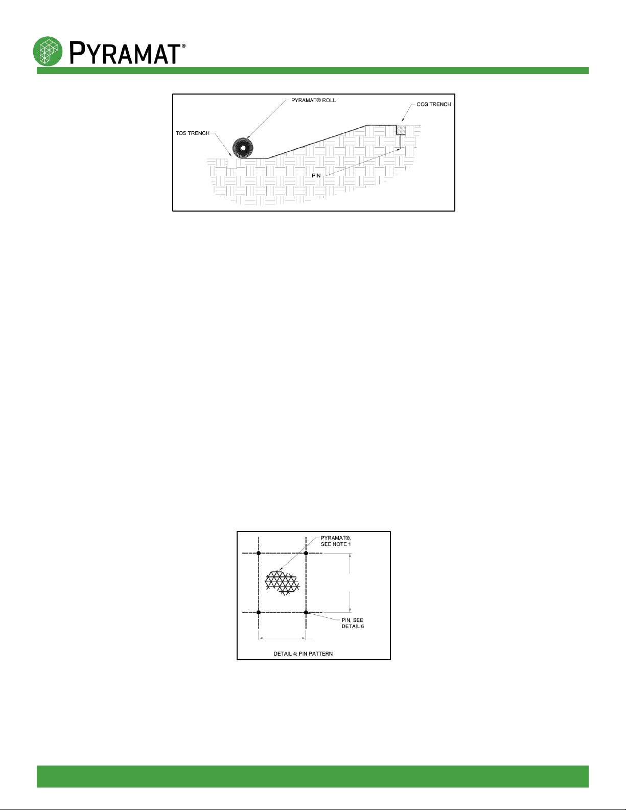
Figure 7: Example Pin Pattern
HORIZONTAL PIN SPACING
PER PIN SCHEDULE
VERTICAL PIN SPACING PER
PIN SCHEDULE

Page 5of 11
Propex Operating Company, LLC - 4019 Industry Drive, Chattanooga, TN 37416 - p 800 621 1273 - www.propexglobal.com
Figure 8: Example of Panel Overlap
Figure 9: Roll End Overlap
OFFSET PINS AS SHOWN TO CREATE A
CHECKERBOARD PATTERN
PINS ON 12” (300 mm)
CENTERS ON ROLL EDGE
OVERLAPS
This manual suits for next models
2


