Proscend 500 User manual

Proscend
Media Converter
500
User Manual
Version 1.00

500 Media Converter User Manual Version 1.00
2
Table of Contents
1DESCRIPTIONS ................................................................................................................................................... 2
1.1 FEATURES............................................................................................................................................................ 2
1.1.1 Ethernet over E1 converter.......................................................................................................................... 2
1.1.2 Ethernet over Serial converter..................................................................................................................... 2
1.2 SPECIFICATION ..................................................................................................................................................... 2
1.3 APPLICATIONS ...................................................................................................................................................... 4
2GETTING TO KNOW ABOUT THE MEDIA CONVERTER......................................................................................... 5
2.1 FRONT PANEL....................................................................................................................................................... 5
2.2 REAR PANEL......................................................................................................................................................... 6
2.3 CONSOLE CABLE ................................................................................................................................................... 7
2.4 POWER CONNECTION ............................................................................................................................................ 7
2.5 RESET BUTTON..................................................................................................................................................... 8
2.6 PROTECTIVE EARTH (FRAME GROUND)TERMINAL ....................................................................................................... 8
3CONFIGURE PROSCEND MEDIA CONVERTER 500 ............................................................................................... 9
3.1 SETUP............................................................................................................................................................. 12
3.1.1 INTERFACE................................................................................................................................................. 13
3.1.2 MODE ........................................................................................................................................................ 14
3.1.3 E1 .............................................................................................................................................................. 15
3.1.3.1 Channel.............................................................................................................................................................16
3.1.3.2 Code..................................................................................................................................................................19
3.1.3.3 AIS.....................................................................................................................................................................20
3.1.3.4 Build_outs.........................................................................................................................................................21
3.1.4 ETHERNET ................................................................................................................................................. 22
3.1.4.1 Auto ..................................................................................................................................................................23
3.1.4.2 Duplex...............................................................................................................................................................24
3.1.4.1 Speed ................................................................................................................................................................25
3.1.5 Serial ......................................................................................................................................................... 26
3.1.5.1 Interface............................................................................................................................................................27
3.1.5.2 Clock .................................................................................................................................................................27
3.1.5.3 Data ..................................................................................................................................................................28
3.1.5.4 RTS ....................................................................................................................................................................28
3.1.5.5 CTS ....................................................................................................................................................................29
3.1.5.6 DSR ...................................................................................................................................................................30
3.1.5.7 DCD...................................................................................................................................................................30
3.1.5.8 Delay .................................................................................................................................................................31
3.1.6 DEFAULT .................................................................................................................................................... 32
3.1.7 REBOOT ..................................................................................................................................................... 33
3.2 STATUS ........................................................................................................................................................... 34
3.2.1 Interface .................................................................................................................................................... 35
3.2.2 Current Perf............................................................................................................................................... 36
3.2.3 Loc_statistics ............................................................................................................................................. 37
3.2.4 clear .......................................................................................................................................................... 39
3.3 SHOW............................................................................................................................................................. 40
3.3.1 System ....................................................................................................................................................... 41

500 Media Converter User Manual Version 1.00
3
3.3.2 Script ......................................................................................................................................................... 42
3.4 REBOOT.......................................................................................................................................................... 43
3.5 DIAG ............................................................................................................................................................... 44
3.5.1 LoopBack Test............................................................................................................................................ 45
3.5.2 Be rt Test .................................................................................................................................................... 46
3.6 UPGRADE ....................................................................................................................................................... 48
3.7 EXIT ................................................................................................................................................................ 50
APPENDIX A. TECHNICAL INFORMATION.............................................................................................................51
APPENDIX B. TERMINOLOGY ...............................................................................................................................56
APPENDIX C. INTERFACE PARAMETER TABLE.......................................................................................................57
APPENDIX D. CONSOLE CABLE .............................................................................................................................58
APPENDIX E. E1 BALANCED CABLE ......................................................................................................................59
APPENDI X F. E1 UNBALANCED CABLE .................................................................................................................60
APPENDIX G. SERIAL INTERFACE PIN ASSIGNMENTS ............................................................................................61
APPENDIX H. V.35 DB25(M) TO M.34(F) ADAPTOR CABLE ....................................................................................63
APPENDIX I. X.21 DB25(M) TO DB15(F) ADAPTOR CABLE ...................................................................................66
APPENDIX J. ETHERNET CABLE............................................................................................................................68


500 Media Converter User Manual Version 1.00
2
1
1
D
De
es
sc
cr
ri
ip
pt
ti
io
on
ns
s
1
1.
.1
1
F
Fe
ea
at
tu
ur
re
es
s
1
1.
.1
1.
.1
1
E
Et
th
he
er
rn
ne
et
t
o
ov
ve
er
r
E
E1
1
c
co
on
nv
ve
er
rt
te
er
r
The Ethernet over E1 converter offers a channelized E1 and 10/100Base-T interface conversion. It can
provide the user with Ethernet over E1 conversion enabling the user to transport Ethernet data over an E1
link.
It converts the Ethernet data into E1 frame format for transmission over the existing TDM (E1) links and then
re-converts the E1 back into Ethernet data the far-end terminal. The device can effectively utilize the
redundant bandwidth of telecom operators existing TDM network to transport Ethernet data with low
investment. It can enable you to do as:
(1) Bridging Ethernet LANs over existing TDM (E1) telecom network
(2) Extending Ethernet networks utilizing TDM (E1) landline based telecom infrastructure
Using telecom network of E1s/PDH/SDH microwave etc. carrying E1s to transport Ethernet data
1
1.
.1
1.
.2
2
E
Et
th
he
er
rn
ne
et
t
o
ov
ve
er
r
S
Se
er
ri
ia
al
l
c
co
on
nv
ve
er
rt
te
er
r
The Ethernet over Serial converters connect serial based equipment across an Ethernet network.
Serial data sent and received on serial ports on the serial to Ethernet adapter are encapsulated in
Ethernet packets in a manner that can best fit the type of data being transported. It can enable you to do as:
(1) Serial cable replacement using Ethernet
(2) Bridging Ethernet LANs over existing Serial network
(3) A pair of this device can offer a cost effective solution for using existing V.35 leased lines for the
transparent Ethernet service.
1
1.
.2
2
S
Sp
pe
ec
ci
if
fi
ic
ca
at
ti
io
on
n
E1 (G.703) interface
• Framing : Unframed/PCM30/PCM31
• Bit rate : 2048 Mbps (Full-Duplex)
• Line code : AMI/HDB3
• Connector : BNC or RJ-48C
• Line impedance : unbalanced 75 ohm(BNC) for coaxial cable or balanced 120 ohm(RJ-48C) for twisted pair
• Complies with ITU-T G.703, G.706, G.732 and G.823

500 Media Converter User Manual Version 1.00
3
• Sending high electric level : ±2.37V for Coaxial Pair 75 ohm
3.00V for Symmetrical Pair 120 Ohm
Sending low electric level : 0V±0.1V
• Receiving electric level: 0~-43dB
• CRC Check : CRC-4 or Non CRC
Serial (V.35) interface
• Connection: DB-25(F)
• Connection: M.34 (Optional)
• Support RS-530, V.35 or V.36/X.21
Ethernet interface
• 10/100Mpbs Half/Full Duplex, Auto-sensing, Auto-Crossover
• Up to 2048 MAC address learning
• Connection: RJ-45 for Ethernet cable
Management
• Configuration with 4 keypads and 16 x 2 LCD display
• Console port (RJ45, RS232C)
• Support firmware upgradeable through console port
• LED Indicator : PWR, ALM TST; E1 SER ETH for CSU/DSU
Loopback Tests & Bert Test
• CSU Loopback
• DSU Loopback
• Build-in 2047 Test pattern & BER Tester
Clock Mode
• Internal Clock
• External Clock
Physical/Electrical
• AC/DC adaptor Input: 100~240VAC @ 50~60Hz / 5VDC 2A
• Power Consumption: 12W Max
• Operation temperature: 0 to 50°C
• Humidity: Up to 95% (non-condensing)

500 Media Converter User Manual Version 1.00
4
1
1.
.3
3
A
Ap
pp
pl
li
ic
ca
at
ti
io
on
ns
s
Media
Converter 500 Media
Converter 500
INTERNET
Proscend
NTU
router
Proscend
NTU
Proscend
NTU
Proscend
NTU
router
Proscend
NTU
Proscend
NTU

500 Media Converter User Manual Version 1.00
5
2
2
G
Ge
et
tt
ti
in
ng
g
t
to
o
k
kn
no
ow
w
a
ab
bo
ou
ut
t
t
th
he
e
M
Me
ed
di
ia
a
C
Co
on
nv
ve
er
rt
te
er
r
This section will introduce hardware of the Media Converter.
2
2.
.1
1
F
Fr
ro
on
nt
t
P
Pa
an
ne
el
l
The front panel contains LEDs which show status of the device.
LED status description on front panel:
LED
Color
Action
Description
PWR Green On Power is on.
Off
Power is off.
ALM Red
On
System loss.
Off
System is working normally
TST Yellow On System is testing for connection.
Off System is working normally
CSU
E1
Green /
Red
Green: Sync
Red: No Sync
SER Green /
Red Green: Sync
Red: No Sync
ETH
Green /
Red Green: Sync
Red: No Sync
DSU
E1
Green /
Red
Green: Sync
Red: No Sync
SER
Green /
Red Green: Sync
Red: No Sync
ETH Green /
Red Green: Sync
Red: No Sync

500 Media Converter User Manual Version 1.00
6
2
2.
.2
2
R
Re
ea
ar
r
P
Pa
an
ne
el
l
The rear panel of Proscend Media Converter 500 is where all of the connections are made.
!
The reset button can be used only in one of two ways.
(1) Press the Reset Button for one second will cause system reboot.
(2) Pressing the Reset Button for four seconds will cause the product loading the factory default setting
and losing all of yours configuration. When you want to change its configuration but forget the user name
or password, or if the product is having problems connecting to the Internet and you want to configure it
again clearing all configurations, press the Reset Button for four seconds with a paper clip or sharp
pencil.
500 Media Converter User Manual Version 1.00
7
2
2.
.3
3
C
Co
on
ns
so
ol
le
e
C
Ca
ab
bl
le
e
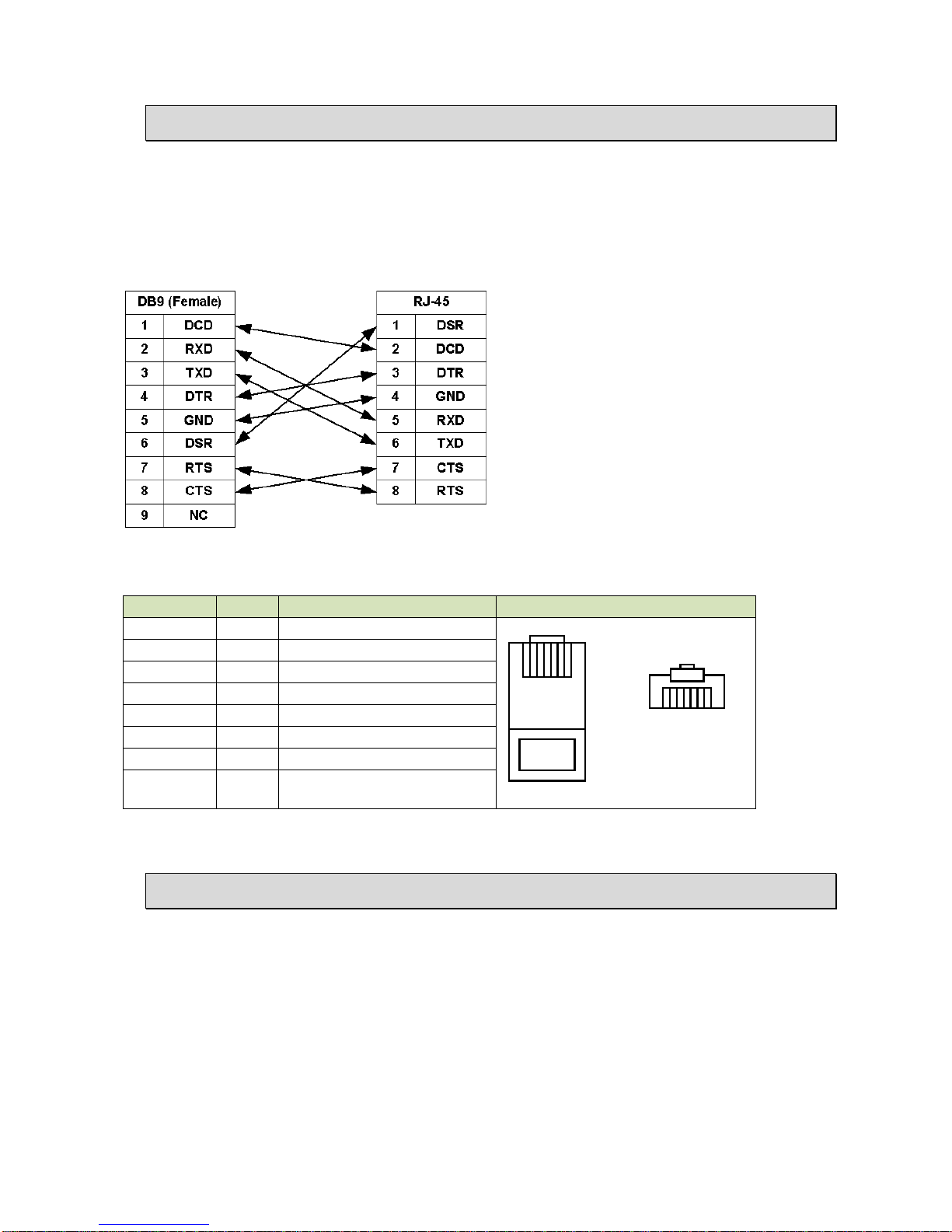
Connect the RJ-45 jack of the console cable to the console port of the EFM modem. Connect the DB-9 female
end to a serial port( COM1 , COM2 or other COM port) of your computer.
The wiring diagram of console cable is as following:
The pin assignment of RJ-45 modular jack on the console cable:
Pin Number
Abbrev.
Description
Figure
1
DSR
DCE ready
1 8
1 8
Top View
Front View
2
DCD
Received Line Signal Detector
3
DTR
DTE ready
4
GND
Signal Ground
5
RXD
Received Data
6 TXD Transmitted Data
7
CTS
Clear to Send
8
RTS
Request to Send
2
2.
.4
4
P
Po
ow
we
er
r
c
co
on
nn
ne
ec
ct
ti
io
on
n
Make sure you are using the correct power source as the AC/DC adaptor. Inset the female end of power
adaptor’s cord into the power receptacle on the rear panel. Connect the power adaptor to an appropriate
power source.

500 Media Converter User Manual Version 1.00
8
2
2.
.5
5
R
Re
es
se
et
t
B
Bu
ut
tt
to
on
n
The reset button can be used only in one of two ways.
(1) Press the Reset Button for two second will cause system reboot.
(2) Pressing the Reset Button for eight seconds will cause the product loading the factory default setting
and losing all of yours configuration. When you want to change its configuration but forget the user name or
password, or if the product is having problems connecting to the Internet and you want to configure it again
clearing all configurations, press the Reset Button for eight seconds with a paper clip or sharp pencil.
2
2.
.6
6
P
Pr
ro
ot
te
ec
ct
ti
iv
ve
e
E
Ea
ar
rt
th
h
(
(F
Fr
ra
am
me
e
G
Gr
ro
ou
un
nd
d)
)
t
te
er
rm
mi
in
na
al
l
The marked lug or terminal should be connected to the building protective earth bus.
The function of protective earth does not serve the purpose of providing protection against electrical shock,
but instead enhances surge suppression on the DSL lines for installations where suitable bonding facilities
exist.
The connector type is M3 machine screw.
500 Media Converter User Manual Version 1.00
9
3
3
C
Co
on
nf
fi
ig
gu
ur
re
e
P
Pr
ro
os
sc
ce
en
nd
d
M
Me
ed
di
ia
a
C
Co
on
nv
ve
er
rt
te
er
r
5
50
00
0
Proscend Media Converter 500 presents a configuration system for users to modify their own media
converters. There are two methods to configure Proscend Media Converter 500:
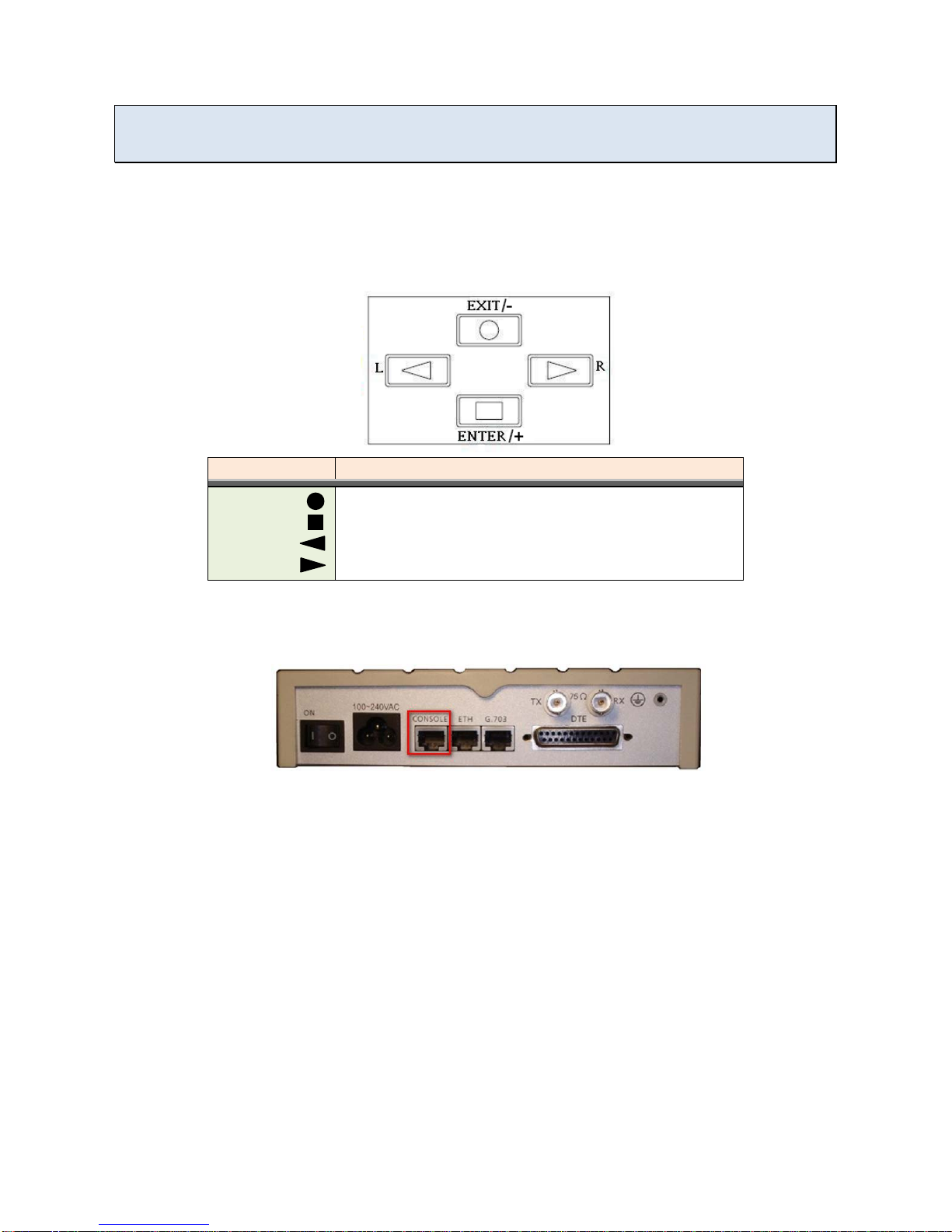
1. By key pad
Users will be able to set a media converter up by the key pad on the right-hand side of a media
converter’s front panel. The following figure shows how the key pad looks like.
Key Pad
Description
Exit/-
Return to previous configuration menu.
Enter/+
Skip to next configuration menu or configure this item.
L
Select other parameter in the same level menu.
R Select other parameter in the same level menu.
2. By console
The other way to control the media converter is by a console port in the back of the converter. (Please
check the figure below to see the console port’s location.)
Once a user connects the converter to his or her computer, he or she can browse the configuration
system by a terminal emulation program, such as, Hyper Terminal.(In this user manual, Tera term is the
main application used.)
The following instructions guide users to access Proscend Media Converter 500 configuration system
through a terminal.

500 Media Converter User Manual Version 1.00
10
Step 1. Open a terminal and change its baud rate to 115200.
Step 2. Press space to allow the terminal to show login messages.
Step 3. The default user name is “admin” and its corresponding password is “admin”.
Step 4. Once a user logs in, he or she will see the main menu as the following figure. Then, the user
can change the converter’s setting with this configuration system.
In Proscend Media Converter 500 configuration system, there are seven major options: setup, status, show,
reboot, diagnosis, upgrade and exit. With these options, users are able to manage their converters, check
their status and upgrade their firmware versions. The following sections demonstrate users how to control
their converters by key pad and by console.

500 Media Converter User Manual Version 1.00
11
Main Menu
SETUP
STAUS
SHOW
REBOOT
DIAG
UPGRADE
EXIT
Interface
Mode
E1
Ethernet
/Serial
Default
Reboot
Interface Current
Perf Loc_Statistics Clear
System Script
LoopBack
BerTest
Kernel FPGA

500 Media Converter User Manual Version 1.00
12
3
3.
.1
1
S
SE
ET
TU
UP
P
Main Menu
SETUP
STAUS
SHOW
REBOOT
DIAG
UPGRADE
EXIT
Interface
Mode
E1
Ethernet
/Serial
Default
Reboot
Interface Current
Perf Loc_Statistics Clear
System Script
LoopBack
BerTest
Kernel FPGA
In “SETUP”, users are allowed to change media converters’ configurations, such as, interface, mode, E1
settings, Ethernet settings, loading the default settings, and reboot the converter. In this section, a brief
description will be given for each available setup.
Choose “setup” in the main menu and users will find out more options as the following photo.

500 Media Converter User Manual Version 1.00
13
3
3.
.1
1.
.1
1
I
IN
NT
TE
ER
RF
FA
AC
CE
E
Users are able to change the interface of media converters by “Interface” function. There are two interface
options available for the converter: “ETH over E1” and “Serial over E1”.
Note: Choose “ETH over E1” to enable Ethernet parameter setups. Choose “Serial over E1” to enable Serial
parameter setups.
From console
Click “tab” on the key board to select an interface option. Press “Enter” to decide which interface the
converter should use.
From key pad
MEDIA CONVERTER
=ETH over E1= SYSTEM
SETUP SETUP
INTERFACE
* INTERFACE *
ETH over E1
* INTERFACE *
Serial over E1
ENTER ENTER
LEFT / RIGHT
LEFT / RIGHT
ENTER
Note: Please make sure to reboot the converter after the configuration is completed.

500 Media Converter User Manual Version 1.00
14
3
3.
.1
1.
.2
2
M
MO
OD
DE
E
“Mode” allows users to choose a clock mode: INCLK or EXTCLK. The clock mode is set according to the
clock mode of the device in the other side of DSL line.
From console
Use “tab” to change the clock mode and press “enter” to save the final decision.
From key pad
MEDIA CONVERTER
=ETH over E1= SYSTEM
SETUP SETUP
MODE
* SHDSL MODE *
INTCLK
* SHDSL MODE *
INTCLK
ENTER ENTER
LEFT / RIGHT
LEFT / RIGHT
ENTER
Mode Description
INTCLK Internal Clock. If the equipment in the other side of E1 is set to external clock, the converter
should be set to internal clock.
EXTCLK
External Clock. If the equipment in the other side of E1 is set to internal clock, the converter
should be set to external clock.

500 Media Converter User Manual Version 1.00
15
3
3.
.1
1.
.3
3
E
E1
1
“E1” includes all E1 parameters, such as, channel, code, AIS, and build_outs.
From console
Choose “E1” to enable more E1 parameter settings.
From key pad
MEDIA CONVERTER
=ETH over E1= SYSTEM
SETUP SETUP
E1
ENTER ENTER ENTER

500 Media Converter User Manual Version 1.00
16
3
3.
.1
1.
.3
3.
.1
1
C
Ch
ha
an
nn
ne
el
l
“Channel” is one of E1 parameters. In this function, users are allowed to configure E1 interface channel with
framer and the corresponding slot number.
From console
Framer Slot Number First Slot
PCM31
FAS
1 to 31
1 to 31
PCM31C
FAS+CRC4
1 to 31
1 to 31
PCM30 FAS+CAS 1 to 30 1 to 31 (can’t use 16)
PCM30C
FAS+CAS+CRC4
1 to 30
1 to 31 (can’t use 16)
FULL
UNFRAMED
(Note: For detail information about the terminologies in the table above, please check A-1.)

500 Media Converter User Manual Version 1.00
17
Channel
Number of slots
1st slot
FULL
(UNFRAMED)
PCM31 PCM31C
31
1
30
1~2
29
1~3
28
1~4
27
1~5
26
1~6
25 1~7
24
1~8
23 1~9
22
1~10
21
1~11
20
1~12
19
1~13
18
1~14
17 1~15
16
1~16
15 1~17
14
1~18
13
1~19
12
1~20
11
1~21
10
1~22
9
1~23
8
1~24
7
1~25
6
1~26
5
1~27
4
1~28
3
1~29
2
1~30
1 1~31
PCM30 PCM30C
30
1
29
1~2
28
1~3
27
1~4
26
1~5
25
1~6
24
1~7
Table of contents
Popular Media Converter manuals by other brands

Broadcast Tools
Broadcast Tools ADC-1 Installation and operation manual

TR-Electronic
TR-Electronic CMS582M 8192/4096 ETC DMS 12H7 KRF Assembly instructions

ELPRO
ELPRO EL-CO-S001 manual

Aventura
Aventura FBR-1GE2LX-SFP instruction manual

Inline
Inline IN1700 Operation manual

myGekko
myGekko GEK.CON.RS2.RS41 quick start guide


