Tone Commander NT1U-220TC User manual

The Tone Commander NT1U-220TC converts an ANSI standard
2B1Q ISDN U-interface from the telco Central Office to an S/T
interface to connect to local customer terminal equipment. Both
point-to-point and multipoint ISDN terminal equipment
configurations are supported.
The NT1U-220TC complies with
ANSI T1.601-1992 and
T1.605-1991 interface standards,
including SC1 and SC2
subchannels, and is compatible
with National-1 and National-2
ISDN standards. In addition, it
may be used as a drop-in
replacement for the AT&T
NT1U-220, and is compatible with
the Tone Commander NT1-220
Rack and the AT&T NT1M-200
rack.
Specifications
NT1U-220TC
Operating Voltage ..............................34–56.5 VDC
Power Consumption ............................625mWtypical
Physical Dimensions ....................6.8“H x 4.4”Wx1.1“D
Weight ..............................................0.7lb.
Operating Temperature ...................0°–50°C(32° – 122° F)
Humidity ...........................5%to95%, non-condensing
Optional Desktop Power Supply (P/N 901034)
Power Requirements......................120VAC,60Hz,15W
Power Output .............................0.6A@42VDCmin.
Short Circuit Protection ............................self-resetting
Physical Dimensions ....................2.2“H x 2.6”W x 3.3“D
Weight .............................................2.0lbs.
Important Safety Instructions
·Never install telephone wiring during a lightning storm.
·Never install telephone jacks in wet locations unless the jack
is specifically designed for wet locations.
·Never touch uninsulated telephone wires or terminals unless
the telephone line has been disconnected at the network
interface.
·Use caution when installing or modifying telephone wires.
·When powering the NT1 through the Power connector, use
only the Tone Commander Desktop Power Supply (P/N
901034-01).
·Do not mount the NT1U-220TC within 12“of a heat source.
FCC Requirements
The Tone Commander NT1U-220TC has been tested and found to
comply with the limits for a Class B digital device, pursuant to Part
15 of the FCC Rules. These limits are designed to provide
reasonable protection against harmful interference when the
equipment is operated in a residential environment. This equipment
generates, uses, and can radiate radio frequency energy and, if not
installed and used in accordance with the instruction manual, may
cause harmful interference to radio communications. However,
there is no guaranty that interference will not occur in a particular
installation. If this equipment does cause harmful interference to
radio or television reception, which can be determined by turning
the equipment off and on, the user is encouraged to try to correct
the interference by one or more of the following measures:
·Where it can be done safely, re-orient the receiving television or
radio antenna.
·To the extent possible, increase the separation between the
telephone equipment and the television, radio, or other
equipment.
·If your telephone equipment runs on AC power, plug your product
into an AC outlet that is not on the same circuit as the one used
by your radio or television receiver.
Termination Switch
The termination switch is located on the back of the NT1. It
must be set prior to mounting the NT1. Available settings are
OFF,100W, and 50W.
Set the termination switch to match the premises wiring
between the NT1 and the terminals. Several typical wiring
configurations are shown below, with the appropriate
termination switch setting.
Fixed or adaptive timing selection is not required.
Connectors
Two terminal connectors are provided for convenient terminal
installation; both are parallel connected to the S/T interface.
Pins 7 and 8 of the Terminal and Line connectors (power pins)
also have metallic interconnection.
NT1U-220TC
Installation
Instructions
!
The use of Category 3 or better unshielded twisted pair
cable with T568A or T568B connector wiring is
recommended. Distances shown are maximum for
24-gauge wiring cable, and may vary for other cable types.
RACK
CONNECTOR
TER M INAL LINEPOW ERTER M INAL
181818
3 – RCV+
6– RC V-
4– XMT+
5– XM T-
7– -48V
8– -48V RTN
TER M INAL (S/T)
CONNECTO RS
4– TIP
5– RING
7– -48V
8– -48V RTN
LINE (U)
CONNECTO R
Mounting
Wall Mounting: Install the supplied mounting screws 5“apart,
and leave the heads out from the mounting surface about ^”.
Hang the NT1 on the screws and slide down to secure. If
necessary, remove the NT1 and adjust the screws to secure the
unit.
Rack Mounting: Insert the NT1U-220TC into the appropriate
slot in the rack. Any unit may be inserted or removed from an
operational rack without affecting the performance of other NT1
units. Power is supplied through the rack.
Powering Arrangements
The NT1 and terminal equipment may be powered through
several different arrangements. In a stand-alone configuration,
the optional Tone Commander Desktop Power Supply (P/N
901034) can be used to power both the NT1 and terminal
equipment. Plug the power supply barrel connector into the
Power jack on the NT1. In a rack configuration, NT1 power is
provided by the rack. In either configuration, terminal power can
be provided through the NT1 by either of the following methods:
PS2 – Direct power feed on Terminal jack pin 7 (-) and pin 8 (+),
8 watts maximum per terminal (16 watts total).
PS1 – Phantom power feed over the transmission pairs,
Terminal jack pins 3/6 (+) and pins 4/5 (-), 4 watts maximum
(total for all terminals).
Mixed power can be used if maximums are not exceeded.
Alternately, a stand-alone NT1 may be powered from a local
power source on the S/T or U interface. The power source must
be able of supplying 1.4 watts at 34-56.5 VDC to the NT1 in
addition to any other loads. Connect the power source to pin
7(-) and pin 8(+) on the Line or Terminal connectors; metallic
interconnection between connectors is provided by the NT1.
CAUTION: Make sure only one power source is connected to
either the S/T or U interface and do not use the Desktop Power
Supply or rack power; damage to equipment may result.
Installation and Troubleshooting
Connect the network U interface from the telco to the Line jack
on the NT1 using the supplied modular cord. Connect terminals
to either Terminal jack using four pair unshielded twisted pair
(UTP) cable, Category 3 or better, with T568A or T568B wiring.
The NT1U-220TC performs a diagnostic self test at power-up or
when the reset button is pushed. All four status indicators will
light for one second during the test.
Wiring connections to the terminal equipment can be verified
before the network line is connected. Connect the terminal
equipment to one of the Terminal (S/T) jacks on the NT1 and
power-up the equipment. As soon as the terminal equipment
attempts to activate, the Line Error LED will flash. After 20
seconds, the NT1 will activate the terminal equipment and the
Terminal Error LED will also flash. Connect only one terminal
device at a time; repeat the test for each terminal device.
The network line can be verified with or without connecting
terminal equipment. Connect the network U interface to the Line
jack on the NT1. Initially, only the Power LED will light. After the
NT1 synchronizes with the network, the Terminal Error LED will
light if no terminal is connected; otherwise, the Active LED will
light. Be patient; in some instances, the network may take up to
3 minutes to synchronize with the NT1.
DC Sealing current is applied by the telco to prevent oxidized
junctions on the network line. Sealing current is usually present,
but not required for NT1 operation. The NT1U-220TC will
display sealing current status when both the network line and at
least one terminal are connected. Lack of sealing current does
not conclusively indicate a bad line connection, since sealing
current is not always provided by the network.
Incorrect termination on the S/T (terminal) interface is a
common cause of unreliable terminal operation. Symptoms
include random data errors, intermittent or steady Terminal Error
indication, or complete terminal malfunction. Network line
synchronization is not affected. Refer to the wiring configuration
diagrams in the Termination Switch section for the appropriate
termination setting.
To fully operate with the network, the terminal equipment must
also be correctly programmed with required operating
parameters (such as SPID, directory number, etc.) that are
provided by your telco. Consult your terminal equipment
documentation for programming instructions.
Reset Button
Press the Reset button (located next to the Power indicator) to
reset the NT1 and force network and terminal
resynchronization. CAUTION: Pressing the Reset button during
normal operation will temporarily disrupt communication
services and will disconnect a call in progress.
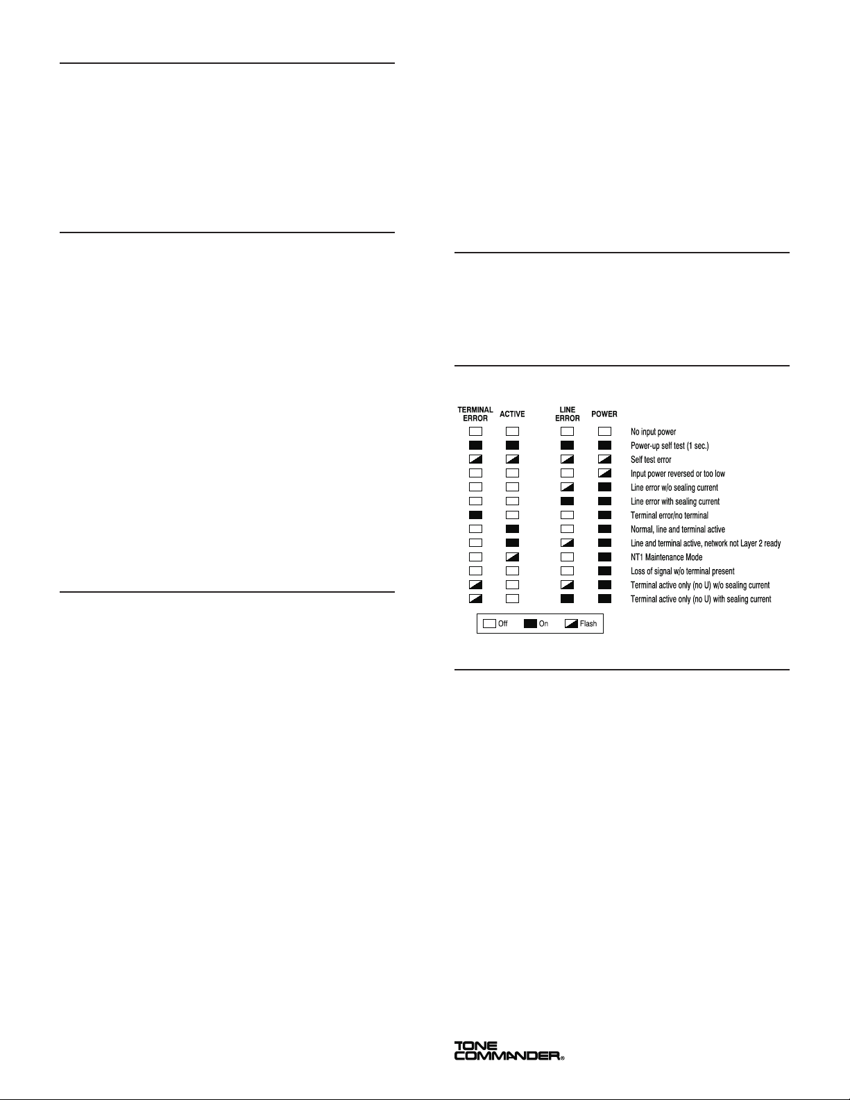
Status Indicators
The operating state of the NT1U-220TC is displayed on four
status indicator LEDs.
Tone Commander Product Warranty
For a period of one year from date of dealer purchase, but not to exceed
16 months from date of manufacture, Tone Commander Systems, Inc.
(Tone Commander) warrants its products to be free from defects in
material and workmanship under conditions of normal use and service.
Tone Commander shall, at its option, repair or replace any defective
product which, in its opinion, has not been misused, damaged, or
improperly installed.
Repair or replacement under this warranty will be performed at Tone
Commander’s factory. Authorization must be obtained from Tone
Commander prior to returning a product for repair. Freight must be
prepaid for all units returned to Tone Commander. Units repaired under
warranty will be return shipped UPS Brown Label (or equivalent), freight
prepaid by Tone Commander.
Products which are older than the warranty period, but less than 7 years
old, or still manufactured by Tone Commander, may be repaired at the
factory for a flat rate charge. Repaired out-of-warranty units are
warranted for 90 days from the date of repair.
The repair or replacement of a product under this warranty represents
the entire obligation of Tone Commander; Tone Commander shall not be
liable for any special or consequential damages resulting from or caused
by any defect, failure, incapacity or malfunction of any of its products.
The foregoing express warranty is in lieu of all other warranties,
express or implied, including but not limited to any implied
warranty of merchantability, fitness, or adequacy for any purpose
or use, quality, productiveness or capacity; Tone Commander, to
the extent permitted by law, hereby disclaims all such other
warranties.
11609 49th Place West – Mukilteo, WA 98275-4255
(800) 524-0024 (425) 349-1000 Fax: (425) 349-1010
www.tonecommander.com
13-102607 Rev. G
October 1999
Popular Media Converter manuals by other brands


Angry Audio
Angry Audio Bluetooth Audio Gadget Preliminary user guide

Digital Solutions
Digital Solutions FIB1-1000MG installation instructions

Cobalt Digital Inc
Cobalt Digital Inc BBG-1190-DEC-MPEG product manual

Cross Technologies
Cross Technologies 2016-1522 instructions

network
network DWC-HD-DMUX user manual

Sumake
Sumake ST-2554A quick start guide