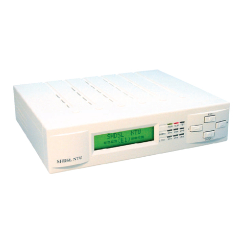
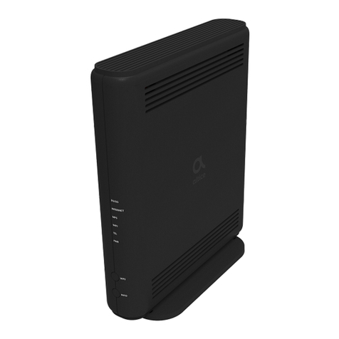
Proscend 5210D User manual

G.SHDSL.bis
Bridge Modem
5210D
User Manual
Version 0.01

G.SHDSL.bis Bridge Modem 5210D User Manual V0.01
1
Table of Contents
1DESCRIPTIONS .................................................................................................................................3
1.1 FEATURES ........................................................................................................................................3
1.2 SPECIFICATION ..................................................................................................................................3
1.3 APPLICATIONS...................................................................................................................................5
2GETTING TO KNOW ABOUT THE MODEM ........................................................................................6
2.1 FRONT PANEL ...................................................................................................................................6
2.1 REAR PANEL .....................................................................................................................................6
2.2 SHDSL.BIS LINE CONNECTOR...........................................................................................................7
2.3 CONSOLE CABLE..............................................................................................................................7
3INSTALL TO THE MODEM .................................................................................................................8
3.1 CHECK LIST ......................................................................................................................................8
3.2 INSTALL THE SHDSL.BIS MODEM .........................................................................................................9
4CONFIGURATION VIA WEB BROWSER............................................................................................ 10
4.1 BASIC SETUP ..................................................................................................................................13
4.1.1 Bridge Mode ..........................................................................................................................13
4.1.2 Reference Diagram ................................................................................................................16
4.2 ADVANCED SETUP ...........................................................................................................................17
4.2.1 SHDSL.bis ...............................................................................................................................17
4.2.1.1 Annex Type ................................................................................................................................. 17
4.2.1.2 Data Rate (N*64kbps)................................................................................................................. 18
4.2.1.3 SNR Margin................................................................................................................................. 18
4.2.1.4 TC Layer ...................................................................................................................................... 18
4.2.1.5 Rate Mode.................................................................................................................................. 18
4.2.2 WAN.......................................................................................................................................19
4.2.2.1 Protocol, IP address and subnet ................................................................................................. 19
4.2.2.2 VPI .............................................................................................................................................. 20
4.2.2.3 VCI .............................................................................................................................................. 20
4.2.2.4 AAL5 Encap................................................................................................................................. 20
4.2.2.5 QoS class .................................................................................................................................... 20
4.2.2.6 QoS PCR...................................................................................................................................... 20
4.2.2.7 QoS SCR ...................................................................................................................................... 21
4.2.2.8 QoS MBS..................................................................................................................................... 21
4.2.3 Bridge ....................................................................................................................................21
4.2.4 VLAN ......................................................................................................................................24
4.2.4.1 802.1Q Tag-Based VLAN ............................................................................................................. 24
4.2.4.2 Port-Based VLAN ........................................................................................................................ 25
4.2.5 STP .........................................................................................................................................27
4.3 STATUS..........................................................................................................................................28
4.3.1 SHDSL.bis ...............................................................................................................................29
4.3.2 LAN ........................................................................................................................................30
4.3.3 WAN.......................................................................................................................................31
4.3.4 INTERFACE .............................................................................................................................32
4.3.5 STP .........................................................................................................................................33
4.4 ADMINISTRATION ............................................................................................................................35
4.4.1 Security ..................................................................................................................................35

G.SHDSL.bis Bridge Modem 5210D User Manual V0.01
2
4.4.2 SNMP .....................................................................................................................................38
4.4.2.1 Community pool......................................................................................................................... 38
4.4.2.2 Trap host pool............................................................................................................................. 39
4.4.3 SYSLOG...................................................................................................................................40
4.4.4 Time Sync...............................................................................................................................41
4.4.4.1 Synchronization with PC ............................................................................................................. 41
4.4.4.2 SNTP v4.0 ................................................................................................................................... 42
4.5 UTILITY .........................................................................................................................................43
4.5.1 System Info ............................................................................................................................43
4.5.2 SYSLOG...................................................................................................................................44
4.5.3 Config Tool .............................................................................................................................45
4.5.3.1 Load Factory Default .................................................................................................................. 46
4.5.3.2 Restore Configuration................................................................................................................. 46
4.5.3.3 Backup Configuration ................................................................................................................. 46
4.5.4 Upgrade.................................................................................................................................47
4.5.5 Logout....................................................................................................................................48
4.5.6 Restart ...................................................................................................................................49
4.6 EXAMPLE.......................................................................................................................................50
4.6.1 LAN-to-LAN connection with bridge Mode ............................................................................50
4.6.1.1 CO side ....................................................................................................................................... 50
4.6.1.2 CPE Side...................................................................................................................................... 51
5CONFIGURATION VIA SERIAL CONSOLE OR TELNET WITH MENU DRIVEN INTERFACE ....................52
5.1 INTRODUCTION ...............................................................................................................................52
5.1.1 Serial Console ........................................................................................................................52
5.1.2 Telnet .....................................................................................................................................52
5.1.3 Operation Interface ...............................................................................................................53
5.1.4 Window structure ..................................................................................................................54
5.1.5 Menu Driven Interface Commands ........................................................................................54
5.2 MAIN MENU ..................................................................................................................................56
5.3 STATUS..........................................................................................................................................56
5.3.1 Shdsl.bis .................................................................................................................................57
5.3.2 Wan .......................................................................................................................................57
5.3.3 Interface ................................................................................................................................58
5.3.4 STP .........................................................................................................................................58
5.4 SHOW...........................................................................................................................................59
5.4.1 System information................................................................................................................59
5.4.2 Configuration information.....................................................................................................59
5.4.3 Configuration with Script format...........................................................................................60
5.5 PING.............................................................................................................................................60
5.6 EXIT..............................................................................................................................................60

G.SHDSL.bis Bridge Modem 5210D User Manual V0.01
3
1 Descriptions
The Proscend 5210D is G.SHDSL.bis bridge modem with four Ethernet interfaces to a computer. It
provides a very stable system installation with a simplified set of configuration options to ensure
problem free operation.
It complies with G.991.2 (2004) standard optimized for small to medium size business
environment. It provides business-class, multi-range from 192Kbps to 5.696Mbps symmetric
payload rates over existing copper wire.
It support four 10Base-T/100Base-T auto-negotiation and auto-MDI/MDIX switching ports to meet
the enterprise need.
1.1 Features
An easy-to-use graphic interface s accessed using any Web browser software for
configuration and management with password control for various application environments
A menu-driven interface/Command-line interface (CLI) for local console and Telnet access
for configuration and management
Four 10/100Mbps Auto-negotiation and Auto-MDI/MDIX switching ports for flexible local area
network connectivity
Fully ATM/EFM protocol stack implementation over SHDSL.bis
Getting enhancements and new features via Internet software upgrade
1.2 Specification
Bridge MODE
Ethernet to SHDSL.bis self learning - Transparent Bridging (IEEE 802.1D)
Supports up to 2048 MAC learning addresses
Management
Easy-to-use web-based GUI for quick setup, configuration and management
Menu-driven interface/Command-line interface (CLI) for local console and Telnet
access
Password protected management and access control list for administration
Software upgrade via web-browser
ATM with Traffic shaping
UBR (Unspecified bit rate)
CBR (Constant bit rate)
VBR-rt (Variable bit rate real-time)
VBR-nrt (Variable bit rate non-real-time)
AAL5 Encapsulation
VC multiplexing and SNAP/LLC

G.SHDSL.bis Bridge Modem 5210D User Manual V0.01
4
Ethernet over ATM (RFC 2684/1483)
WAN Interface
SHDSL.bis: ITU-T G.991.2 (2004) Compliance
Annex A, B and AB supported
Encoding scheme: 16-TCPAM/32-TCPAM
Data Rate: N x 64Kbps ( N=3 to 89)
Impedance: 135 ohms
LAN Interface
4-ports switching hub
10/100Mbps, half/full duplex auto-sensing and auto-negotiation
Auto-MDI/MDIX (Automatic cross-over)
Hardware Interface
WAN: RJ-45 connector
LAN: RJ-45 connector
Console: DB-9(Female) connector
Reset Button: Reset button for factory default
DC-IN: 12V DC power input connector
Indicators
General: PWR
WAN: LNK, ACT
LAN: 1,2,3,4 LNK/ ACT
SHDSL.bis: ALM
Physical/Electrical
Dimensions: 18.7 x 3.3 x 14.5cm (WxHxD)
Power: 100~240VAC (via power adapter)
Power consumption: 9 watts maximum.
Temperature: 0~45˚C
Humidity: 0%~95%RH (non-condensing)
Memory
2MB Flash Memory, 16MB SDRAM
Products’ Information
5210D G.SHDSL.bis Bridge Modem with 4-ports LAN

G.SHDSL.bis Bridge Modem 5210D User Manual V0.01
5
1.3 Applications

G.SHDSL.bis Bridge Modem 5210D User Manual V0.01
6
2 Getting to know about the modem
This section will introduce hardware of the modem.
2.1 Front Panel
The front panel contains LEDs which show status of the modem.
LED status description on front panel:
LEDs
Active
Description
PWR
On
Power adaptor is connected to the modem
WAN
LNK
On
SHDSL.bis line connection is established
Blink
SHDSL.bis handshake
ACT
Blink
Transmit or received data over SHDSL.bis link
LAN
(1,2,3,4)
On
Ethernet cable is connected to LAN
Blink
Transmit or received data over LAN
ALM
On
SHDSL.bis line connection is dropped
Blink
SHDSL.bis self test
2.1 Rear Panel
The rear panel of SHDSL.bis bridge modem is where all of the connections are made.
Connectors description on rear panel:
Connector
Description
DC-IN
To connect your power outlet use the power adaptor inlet that comes with
your package.
LAN (1,2,3 and 4)
Ethernet 10/100BaseT auto-sensing and auto-MDIX for LAN port (RJ-45) to
connect the unit to an access point, a network hub, or the Ethernet port of a
computer.
CONSOLE
RS- 232 Console port for system configuration and maintenance (DB-9F)
LINE
SHDSL.bis interface for WAN port (RJ-45)
RES
Reset button to reboot or reset your modem to factory default setting (All
customized settings that you have saved will be lost).

G.SHDSL.bis Bridge Modem 5210D User Manual V0.01
7
The reset button can be used only in one of two ways.
(1) Press the Reset Button for one second will cause system reboot.
(2) Pressing the Reset Button for four seconds will cause the product loading the factory default
setting and losing all of yours configuration. When you want to change its configuration but
forget the user name or password, or if the product is having problems connecting to the
Internet and you want to configure it again clearing all configurations, press the Reset
Button for four seconds with a paper clip or sharp pencil.
2.2 SHDSL.bis Line Connector
Below figure show the SHDSL.bis line cord plugs pin asignment:
2.3 Console Cable
Below figure show the cosole cable pins asignment:
Pin Number
Description
Figure
1
12345
6789
Front view of DB-9(F) of the Console
Cable
2
RXD
Receive Data
3
TXD
Transmit date
4
5
G
Signal Groung
6
7
8
9

G.SHDSL.bis Bridge Modem 5210D User Manual V0.01
8
3 Install to the Modem
This guide is designed to let users through Web Configuration or serial console with G.SHDSL .bis
modem in the easiest and quickest way possible. Please follow the instructions carefully.
Note: There are three methods to configure the modem: serial console, Telnet and Web Browser.
Only one configuration application is used to setup the modem at any given time. Users
have to choose one method to configure it.
For Web configuration, you can skip item 3.
For Serial Console Configuration, you can skip item 1 and 2.
For Telnet configuration, you can skip 3.
3.1 Check List
(1) Check the Ethernet Adapter in PC or NB
Make sure that Ethernet Adapter had been installed in PC or NB used for configuration of the
modem. TCP/IP protocol is necessary for web configuration, so please check the TCP/IP protocol
whether it has been installed.
(2) Check the Web Browser in PC or NB
According to the Web Configuration, the PC or NB need to install Web Browser, IE or Netscape.
Note: Suggest to use IE5.0, Netscape 6.0 or above and 800x600 resolutions or above.
(3) Check the Terminal Access Program
For Serial Console and Telnet Configuration, users need to setup the terminal access program
with VT100 terminal emulation.

G.SHDSL.bis Bridge Modem 5210D User Manual V0.01
9
3.2 Install the SHDSL.bis Modem
!
To avoid possible damage to this modem, do not turn on the modem before Hardware Installation.
Connect the power adapter to the port labeled DC-IN on the rear panel of the product.
Connect the Ethernet cable.
The device supports auto-MDIX switching so both straight through and cross-over Ethernet
cable can be used.
Connect the phone cable to the modem and the other side of phone cable to wall jack.
Connect male end of RS-232 cable to the product and female end to any free COM port of
PC.
Connect the power adapter by plugging power supply.
Wire connection for SHDSL.bis modem

G.SHDSL.bis Bridge Modem 5210D User Manual V0.01
10
4 Configuration via Web Browser
Step.1 Click the start button. Select setting and control panel.
Step.2 Double click the network icon.
In the Configuration window, select the TCP/IP protocol line that has been associated with your
network card and then click property icon.
Choose IP address tab.
Select Specify an IP address.
Type IPAddress and Subnet Mask items.
Click OK button.
Open IE or Netscape Browser to connect the modem. Type
http://192.168.0.1

G.SHDSL.bis Bridge Modem 5210D User Manual V0.01
11
The default IP address and sub net-mask of the modem is 192.168.0.1 and 255.255.255.0.
Type User Name root and Password root and then click OK.
The default user name and password both is root. For the system security, suggest changing them
after configuration.
Note: After changing the User Name and Password, strongly recommend you to save them
because another time when you login, the User Name and Password have to be used the
new one you changed.

G.SHDSL.bis Bridge Modem 5210D User Manual V0.01
12
Function overview
Following is the function overview of G.SHDSL.bis modem.

G.SHDSL.bis Bridge Modem 5210D User Manual V0.01
13
4.1 Basic Setup
The Basic Setup contains operation mode, basic LAN and WAN interface set up. User can use it to
completely setup the modem. After successfully completing it, you can access Internet or as LAN
extension. This is the easiest and possible way to setup the modem.
Note: The advanced functions are only for advanced users to setup advanced functions. The
incorrect setting of advanced function will affect the performance or system error, even
disconnection.
Click Basic for basic installation.
4.1.1Bridge Mode
Parameter Table:
SHDSL.bis
□CO side □CPE side
LAN
IP address
Subnet Mast
Gateway
Host Name
WAN1
VPI
VCI
Encapsulation
□VC-mux □LLC
The flow chart of bridge mode setup:

G.SHDSL.bis Bridge Modem 5210D User Manual V0.01
14
Setup up system mode and SHDSL.bis mode
This modem can be setup as one of two SHDSL.bis working mode: CO side(Central Office) and
CPE side (Customer Premises Equipment). For connection with DSLAM, the SHDSL.bis modem
working mode is CPE. For “LAN to LAN” connection, one side must be CO and the other side must
be CPE.
Set up (a) LAN IP address , Subnet Mask, Gateway and Host Name
(b) WAN1 VPI,VCI and Encapsulation
For example,
(a) LAN IP address , Subnet Mask, Gateway and Host Name
LAN:
IP: 192.168.0.1
Subnet Mask: 255.255.255.0
Gateway: 192.168.0.254
Host Name: SOHO
Some of the ISP requires the Host Name as identification. You may check with ISP to see if your
Internet service has been configured with a host name. In most cases, this field can be ignored.
(b) WAN1 VPI,VCI and Encapsulation
WAN1:
VPI: 0
VCI: 32
Encap: Click LLC

G.SHDSL.bis Bridge Modem 5210D User Manual V0.01
15
Click Next to review the setting data:
The screen will prompt the new configured parameters. Checking the parameters and Click
Restart The modem will reboot with the new setting or Continue to configure another parameters.

G.SHDSL.bis Bridge Modem 5210D User Manual V0.01
16
4.1.2Reference Diagram
For bridge modem, it will act as a pass-through device and allow the workstations on your LAN to
have public addresses directly on the internet.
EoA (Ethernet-over-ATM) protocol is commonly used to carry data between local area networks
that use the Ethernet protocol and wide-area networks that use the ATM protocol. Many
telecommunications industry networks use the ATM protocol. ISPs who provide DSL services
often use the EoA protocol for data transfer with their customers' DSL modems.
EoA can be implemented to provide a bridged connection between a DSL modem and the ISP. In
a bridged connection, data is shared between the ISP's network and their customer's as if the
networks were on the same physical LAN. Bridged connections do not use the IP protocol. EoA
can also be configured to provide a routed connection with the ISP, which uses the IP protocol to
exchange data.

G.SHDSL.bis Bridge Modem 5210D User Manual V0.01
17
4.2 Advanced Setup
Advanced setup contains SHDSL.bis, LAN, WAN, Bridge, VLAN and STP parameters.
4.2.1SHDSL.bis
You can setup the Annex type, data rate and SNR margin for SHDSL.bis parameters in SHDSL.bis.
Click SHDSL.bis
Enter Parameters in SHDSL.bis
4.2.1.1 Annex Type

G.SHDSL.bis Bridge Modem 5210D User Manual V0.01
18
There are two Annex types: Annex AF, Annex BG . If the modem must connect to your ISP,
please check them about it. If your modem configed to point to point application, you must choose
one of the two types according to which line rate you need.
4.2.1.2 Data Rate (N*64kbps)
You can setup the SHDSL.bis data rate in the multiple of 64kbps. The data rate repesent by N
vaule.
N can use 3 to 36, such that 192kbps to 2304bps. The default data rate is 2304Kbps (n=36).
It can set SHDSL.bis as adaptive mode when you set Data Rate is 0. The modem will adapt the
data rate according to the line status.
4.2.1.3 SNR Margin
This is an index of line connection quality. You can see the actual SNR margin in STATUS
SHDSL.bis. The larger is SNR margin, the better is line connection quality.
The range of SNR Margin is -10 to 10.
If you set SNR margin in the field as 3, the SHDSL.bis connection will drop and reconnect when
the SNR margin is lower than 3. On the other hand, the device will reduce the line rate and
reconnect for better line connection quality.
The screen will prompt the parameters that will be written in NVRAM. Check the parameters
before writing in NVRAM.
Press Restart to restart the modem working with new parameters or press continue to setup
another parameter.
4.2.1.4 TC Layer
There are two TC layer setting on this modem: EFM layer and ATM layer. It is based on the
networks connected: ATM-based Access Network or Ethernet-based Access Network.
4.2.1.5 Rate Mode
For adaptive mode, you have to configure in Rate Mode. It will adapt the optimal data rate
according to the line status.

G.SHDSL.bis Bridge Modem 5210D User Manual V0.01
19
4.2.2WAN
The modem can support up to 8 PVCs. WAN 1 was configured via BASIC menu except QoS. If
you want to setup another PVCs such as WAN 2 to 8, those parameters are setup on the pages of
WAN under ADVANCED. On the other hand, you don’t need to setup WAN except you apply two
or more Internet Services with ISPs.
Enter the parameters:
4.2.2.1 Protocol, IP address and subnet
Protocol: You can disable or enable this WAN ports. When enable, there have only one protocol
Table of contents
Other Proscend Modem manuals
Popular Modem manuals by other brands
Telenetics
Telenetics MIU/PowerPort 202T Installation & operation manual

Huawei
Huawei E397U-53 quick start guide
Atlantis Land
Atlantis Land I-Storm USB ADSL modem A01-AU2 Multilanguage manual

T-Mobile
T-Mobile Web n Walk Stick quick start guide
Digi
Digi XB3-C-G1-UT-001 user guide
Dantel
Dantel 49013 Installation & operation manual
