eWON NETBITER EC350 User manual

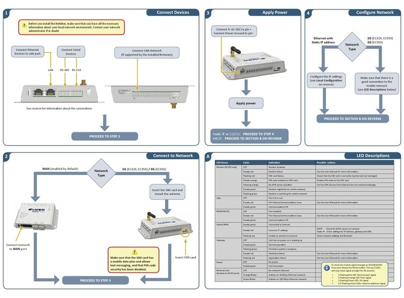
1Connect Devices 3Apply Power 4Configure Network
2Connect to Network
ALED DescripƟons
PROCEED TO STEP 2
PROCEED TO STEP 3
Insert the SIM card and
mount the antenna
WAN (enabled by default) 2G/3G (EC350 only)
Make sure that the SIM card has
a mobile data plan and allows
text messaging, and that PIN code
security has been disabled.
Apply power
StaƟc IP or 2G/3G: PROCEED TO STEP 4
DHCP: PROCEED TO SECTION B ON REVERSE
LED Name Color IndicaƟon Possible acƟons
Modem (EC350 only) OFF Modem disabled
Steady red Modem failure See the User Manual for more informaƟon.
Flashing red SIM card failure Check that the SIM card is correctly inserted and not damaged.
Steady orange PIN code enabled on SIM card Disable PIN code on the SIM card.
Flashing orange No APN server specified Set the APN (Access Point Name) from the onboard webpage.
Steady green Modem registered on mobile network
Flashing green Modem is searching for mobile network.
RS485/RS232 OFF Port disabled
Steady red Port failure/communicaƟons issue See the User Manual for more informaƟon.
Steady green CommunicaƟons OK
Uplink/WAN Steady green Connected to Internet
Steady red Incorrect IP seƫngs DHCP: Check for DHCP server on network.
StaƟc IP: Check seƫngs for IP address, gateway and DNS.
Flashing red Unable to connect to Internet Check network seƫngs and firewalls.
Gateway OFF Unit has no power, or is starƟng up
Steady green Normal operaƟon
Flashing green Firmware update in progress.
Steady red Hardware failure See the User Manual for more informaƟon.
Flashing red ApplicaƟon failure See the User Manual for more informaƟon.
Power OFF No power
Steady green Unit has power
Ethernet Link
(located on RJ-45 ports)
OFF No network detected
Orange flicker AcƟvity on 10 Mbps Ethernet network
Green flicker AcƟvity on 100 Mbps Ethernet network
See reverse for informaƟon about the connecƟons
Insert SIM card
Connect network
to WAN port
Connect Serial
Devices
Make sure that there is a
good connecƟon to the
mobile network.
See LED DescripƟons.
Connect 12–48 VDC to pin +
Connect Power Ground to pin -
Ethernet with
StaƟc IP address
2G/3G
(EC350 only)
PROCEED TO SECTION B ON REVERSE
Configure IP seƫngs.
See secƟon C on reverse.
To check the mobile signal strength on EC350:
Press and release the Mode buƩon. The top 5 LEDs
will now show signal strength for 60 seconds:
• 1 Flashing Red LED: No/unknown signal
• 1 Flashing Orange LED: Poor signal
• 1 Flashing Green LED: OK signal
• 2-5 Flashing Green LEDs: Good to opƟmum signal
RS-485 RS-232
S
S
I
M
Connect Ethernet
Devices to LAN port
LAN
Before you install the Netbiter, make sure that you have all the necessary
informaƟon about your local network environment. Contact your network
administrator if in doubt.
Select
Network
Type
Network
Type

B
D
CE
AcƟvate the Netbiter
ConnecƟons
Local ConfiguraƟon Technical Data
EC310/EC350
INSTALLATION GUIDE
Local ConfiguraƟon via USB
Connect a USB Micro B cable between a computer and the USB port on the
Netbiter. The USB device driver will create a virtual network interface on the
computer, with an IP address in the range 169.254.200.xxx.
Accessing the local configuraƟon
Enter the IP address 169.254.200.200 in a web browser.
The default username for the local configuraƟon pages is admin.
The password is the AcƟvaƟon Code supplied with the unit.
The Netbiter must be acƟvated to be able to communicate with Netbiter Argos.
This requires the System ID and AcƟvaƟon Code, both of which are provided on a
printed sheet included with the Netbiter.
To open a new account on Netbiter Argos:
1. Go to
www.netbiter.net and click on Create an account.
2. Follow the instrucƟons and log in to the new account.
3. Select the primary use for the unit and click on AcƟvate.
To use an exisƟng Netbiter Argos account:
1. Go to www.netbiter.net and log in to your Argos account.
2. Open the menu Management >> All Systems >> Add system.
Refer to the online help in Argos if needed (see below).
Requirements for Mobile CommunicaƟon
If the SIM card is not a Netbiter SIM card the following informaƟon is needed:
• The phone number for the SIM card
• The access point name (APN)
• The username and password (if required by the operator)
The informaƟon can be entered in two ways:
• In the local configuraƟon pages under Modem seƫngs (see secƟon C)
• In Netbiter Argos on the Mobile network configuraƟon page
The PIN code for the SIM card must be disabled.
Online Help
The help system in Netbiter Argos can be accessed by clicking on the icon in the
top right corner of the web page.
HMS Industrial Networks AB
Box 4126
300 04 Halmstad
Sweden
Phone +46 (0)35 - 17 29 00
Fax +46 (0)35 - 17 29 09
E-mail [email protected]
Web www.hms-networks.com
Support www.netbiter.com/support
©2016 HMS Industrial Networks - All rights reserved
HMS reserves the right to make modificaƟons without prior noƟce.
For a Netbiter SIM card the APN seƫngs are pre-configured on
Netbiter Argos and the PIN code is disabled upon delivery.
Package Contents DescripƟon
Netbiter EC310 or EC350
Connectors Connectors for I/O, RS-232 and RS-485 teminals
System ID/AcƟvaƟon code Printed document with installaƟon credenƟals
InstallaƟon Guide This document
Stub antenna NB1005 only
DIN Rail MounƟng Kit NB1005 and NB1007 only
Once the Netbiter is online at Netbiter Argos, check
that the unit is running the latest firmware.
SP1829 3.10 2016-10-03
Field wiring terminals must be connected with minimum wire size 24 AWG
Power Connector
SIM Card Slot (EC350 only)
I/O Terminal Block RS-232RS-485
GPS antenna connector
(EC350 only)
WAN
Pin DescripƟon
Rx Rx Recieve Input RS-232
Tx Tx Transmit Output RS-232
GND Signal ground
Pin DescripƟon
A RS-485 Line A (+)
B RS-485 Line B (-)
COM ISO GND (Isolated ground)
Micro USB
Connector ProtecƟve Earth
(for Ethernet ports)
Pin Label DescripƟon
1 Relay NO Relay Output, NO, Isolated
2 Relay COM Relay Output, COM, Isolated
3 DI1+ Digital input 1 current source
4 DI1- Digital input 1
5 DI2+ Digital input 2 current source
6 DI2- Digital input 2
7 Analog In AI1 Analog Input 1
8 Analog In AI2 Analog Input 2
9 Analog In AI3 Analog Input 3
10 Analog In AI4 Analog Input 4
11 Analog IN COM Analog Ground
I/O Terminal Block
v
v
e
e
E
Ea
(
LAN
2G/3G antenna connector
(EC350 only)
• Do not connect power to the digital inputs!
• Relay max 24 V AC/DC, 1 A
Mode BuƩon
P
ow
er
r
C
C
on
on
ne
ct
or
SIM
Ca
Ca
rd
r
Slot
(EC350
only)
I/
O Terminal Blo
ck
k
US
US
B
B
ec
t
o
r
M
od
e
e
Bu
Bu
Ʃ
on
U
US
S
S
B
B
B
e
e
B
B
B
Bu
Ʃ
Ʃ
Ethernet link indicators
i
i
nk
nk
nk
nk
ind
or
or
r
s
s
s
s
Order Code
EC310: NB1007
EC350: NB1005
EC350 (no antenna): NB1008
Mobile communicaƟon (EC350 only)
5-band 3G/UMTS (WCDMA/FDD):
800/850, 900, 1900, 2100 MHz
Quad-band GSM/GPRS:
850, 900, 1800, 1900 MHz
1 Relay Output
2 Digital Inputs (dry contact type)
4 Analog Inputs
V, mA (all 4 inputs)
Pt100 (2 inputs)
Serial Port #1
RS-232 (Tx, Rx, GND)
Serial Port #2
RS-485
Antenna Connector Mobile (EC350 only)
SMA female
Antenna Connector GPS (EC350 only)
SMA female (acƟve or passive antenna)
USB Interface
Micro USB, USB 2.0
Protocols
Modbus RTU
MounƟng
DIN rail (EN 50022)
Wall mounƟng
Dimensions (H x W x D)
25.6 x 135 x 92 mm
Temperature
OperaƟng: -40 °C to +65 °C
Storage: -45 °C to +85 °C
Humidity range
5–95 % RH, non-condensing
Input Voltage
12–48 VDC
Recommended Power Supply
24 VDC, 25 W, LPS
Power ConsumpƟon, typical
EC310: 2.5 W
EC350: 4.5 W
CerƟficaƟons
EC310: CE, CULUS
EC350: CE, CULUS, FCC, IC, PTCRB
Contains FCC ID: QIPPHS8-P
Contains IC ID: 7380A-PHS8P
R
AN
S
S
3
23
2
To maintain CE compliance, DC cable
length must not exceed 3 meters and
shielded Ethernet cables must be used.
This manual suits for next models
1
Other eWON Modem manuals
Popular Modem manuals by other brands
Kathrein
Kathrein ESM 20 user manual
Wireless Matrix
Wireless Matrix MBS2-LP EDGE user guide
Hughes
Hughes dishNET HT 1000 Replacement guide
Submeter Solution
Submeter Solution NoWire WebConnect Installation notes
US Robotics
US Robotics 56 K SOFTMODEM - COMMAND REFERENCE REV 1 Command reference
EnergyICT
EnergyICT WebRTU Z2 installation guide
