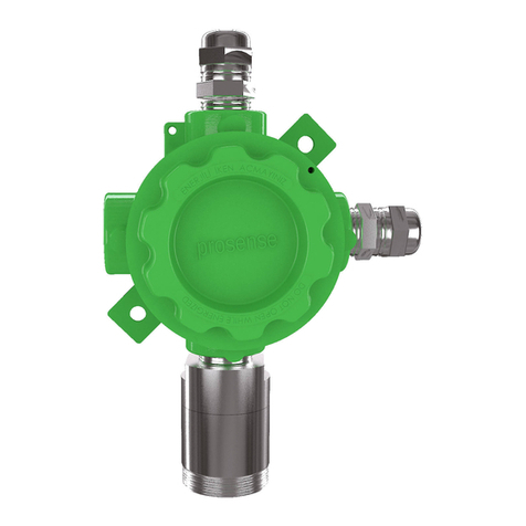
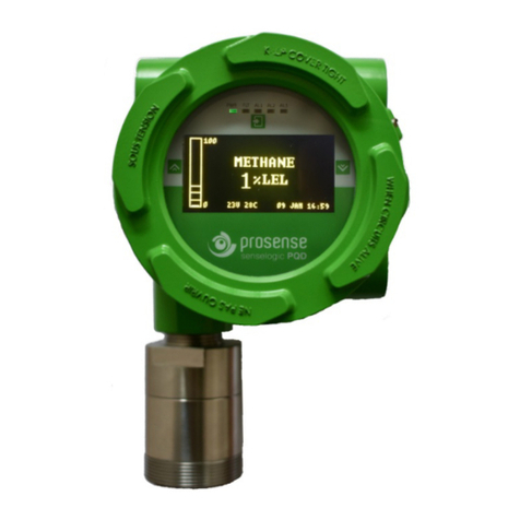
Prosense PQ Series User manual

PRS-UM-PQ-EN-Rev.05-18.06.2020 2
WARNING!
READ THIS INSTRUCTION FIRST!
This manual must be carefully read by all persons who have or will have the
responsibility for installing, using or servicing this product.
Like any equipment, this product will perform as designed only if installed,
used and serviced in accordance with the manufacturer’s instructions.
Otherwise, it could fail to perform as designed and persons who rely on this
product for their safety could suffer severe personal injury or death.
The warranties made by Prosense with respect to this product are voided if the
product is not installed, used and serviced in accordance with the instructions
in this user guide. Please protect yourself and other by following them.
Important Remark
The detector has been factory-tested before delivery. The commissioning has
to be terminated by a function test of the complete gas detection system.
DO NOT REMOVE COVER WHEN ENERGISED!
ELECTROSTATIC HAZARD - CLEAN ONLY WITH A DAMP CLOTH!

PRS-UM-PQ-EN-Rev.05-18.06.2020 3
Contents
Safety Information...................................................................................................................................... 5
Strictly follow the Instructions for Use............................................................................................... 5
Maintenance ...................................................................................................................................... 5
Use in areas subject to explosion hazards ......................................................................................... 5
Liability for proper function or damage ............................................................................................. 5
Intended Use ...................................................................................................................................... 6
Introduction................................................................................................................................................ 8
Detector body........................................................................................................................................... 11
Sensor Head.............................................................................................................................................. 12
Installation................................................................................................................................................ 12
Mounting the detector............................................................................................................................. 14
Electrical connections............................................................................................................................... 15
Cabling...................................................................................................................................................... 17
Detector grounding .................................................................................................................................. 18
Default configuration ............................................................................................................................... 19
Detector Configuration............................................................................................................................. 20
4-20 mA output: ................................................................................................................................... 20
RS485 serial communication output: ................................................................................................... 20
Detector Relay module:........................................................................................................................ 21
Oxygen detectors: ................................................................................................................................ 22
System Status ........................................................................................................................................... 23
Commissioning ......................................................................................................................................... 24
Commissioning PQD ............................................................................................................................. 24
Commissioning PQN ............................................................................................................................. 25
Detector Settings...................................................................................................................................... 26
Entering the menu:............................................................................................................................... 26
Menu structure..................................................................................................................................... 27
Alarm Settings ...................................................................................................................................... 27
Configure .............................................................................................................................................. 29
Change date and time ...................................................................................................................... 29
Change Modbus address .................................................................................................................. 30
Change Analogue Output ................................................................................................................. 30
Display Parameters............................................................................................................................... 30
Change Language ............................................................................................................................. 31
Change Zero Suppression ................................................................................................................. 31
Change password ............................................................................................................................. 31
Detector Model ................................................................................................................................ 32
Bump Test............................................................................................................................................. 32
Change Test Interval......................................................................................................................... 33
Adjust Inhibit warning ...................................................................................................................... 33
Information Menu options................................................................................................................... 34
Display Event Logs ............................................................................................................................ 34
Display Concentration Trends .......................................................................................................... 34
Display Measurements..................................................................................................................... 35
Display Transmitter information ...................................................................................................... 35
Display Transmitter information ...................................................................................................... 35

PRS-UM-PQ-EN-Rev.05-18.06.2020 4
Test Menu Options ............................................................................................................................... 36
Run Inhibit test ................................................................................................................................. 36
Run Display test................................................................................................................................ 37
Run Relay test................................................................................................................................... 37
Run Analogue Output test................................................................................................................ 38
Run Bump Test ................................................................................................................................. 38
Calibration ................................................................................................................................................ 40
Set Reference Gas details..................................................................................................................... 41
Set Calibration Cycle............................................................................................................................. 42
Zero Calibration .................................................................................................................................... 42
Span Calibration ................................................................................................................................... 43
Cancel Calibration................................................................................................................................. 43
Maintenance ............................................................................................................................................ 44
Proactive maintenance:........................................................................................................................ 44
Operational Life:................................................................................................................................... 44
Servicing ............................................................................................................................................... 44
Battery .................................................................................................................................................. 44
Sensor replacement: ............................................................................................................................ 45
Pellistor sensor replacement:........................................................................................................... 45
Electrochemical sensor: ................................................................................................................... 45
Infrared Sensor:................................................................................................................................ 45
Sensor PCB replacement: ................................................................................................................. 46
Sinter replacement:.............................................................................................................................. 46
Sensor head replacement: ................................................................................................................... 46
Detector Transmitter board replacement:........................................................................................... 47
PQD Detector Display Module replacement: ....................................................................................... 47
Detector Relay Module replacement:.................................................................................................. 48
Status Codes:............................................................................................................................................ 49
Spare Parts ............................................................................................................................................... 50
General specification................................................................................................................................ 52
SAFETY INSTRUCTIONS FOR HAZARDOUS AREA INSTALLATION .............................................................. 53
Certificate ................................................................................................................................................. 55
Declaration ............................................................................................................................................... 58
Warranty statement................................................................................................................................. 59

PRS-UM-PQ-EN-Rev.05-18.06.2020 5
Safety Information
Ensure that this Operating Manual is read and understood BEFORE installing / operating /
maintaining the equipment. Pay particular attention to Warnings and Cautions. All document
Warnings are listed here and repeated where appropriate at the start of the relevant
chapter(s) of this Operating Manual. Cautions appear in the sections/sub-sections of the
document where they apply.
Strictly follow the Instructions for Use
Any use of the detectors requires full understanding and strict observation of these
instructions. The detector is only to be used for purposes specified here.
The cover on Detector must be kept tightly closed until power to the detector is isolated
otherwise ignition of a flammable atmosphere can occur. Before removing the cover for
maintenance or calibration purposes, ensure the surrounding atmosphere is free of
flammable gases or vapours.
Detectors must be protected from extreme vibration and direct sunlight in hot environments
as this may cause the temperature of the detector to rise above its specified limits and cause
premature failure.
Maintenance
It is recommended to obtain a service contract Prosense to carry out all repairs. Only
authentic Prosense spare parts must be used, substitute components may invalidate the
certification and warranty of the detector. Maintenance and calibration operations must only
be performed by qualified service personnel.
Use in areas subject to explosion hazards
Equipment or components which are used in potentially explosive atmospheres and have
been tested and approved according to international or European regulations may be used
only under the conditions specified here. Modifications of components or the use of faulty or
incomplete parts are not permitted. In case of repairs of equipment or components, the
national regulations must be observed.
Liability for proper function or damage
The liability for the proper function of the detector is irrevocably transferred to the owner or
operator to the extent that the detector is serviced or repaired by personnel not employed or
authorized by Prosense or if the sensing head is used in a manner not conforming to its
intended use. Prosense cannot be held responsible for damage caused by non-compliance
with the recommendations given above. The warranty and liability provisions of the terms of
sale and delivery of Prosense are likewise not modified by the recommendations given above.

PRS-UM-PQ-EN-Rev.05-18.06.2020 6
Intended Use
The PQ series detectors are intended to be used for stationary, continuous monitoring for
combustible gas/air or vapour/air mixtures below the Lower Explosion Limit (LEL) and toxic
gas/air mixtures in particule per million (PPM) units. The detectors are marked by the device
categories II 2G that can be operated in hazardous areas with potentially explosive
atmospheres of zones 1 and 2. The type of protection for gas explosion protection according
to device category 2 (zones 1 or 2) is flameproof enclosure and increased safety, "db". The
enclosure protection is IP 65.
According to the ATEX Directive 2014/34/EU the detector is an assembly consisting of three
components (Sensor Head, enclosure and cable gland), where all these three components are
type approved according to ATEX Directive 2014/34/EU and marked by the device category II
2G. Thus this detector is suitable to be operated in hazardous areas with potentially explosive
atmospheres of zone 1 and zone 2. The PQ series detector comprises a gas sensor type Ex-
proof (protection type flameproof enclosure db type). PQ Series detector for flammable gases
performs % 0 to % 100 LEL measurement range; for toxic gases the measurement range would
be vary. The measurement range and environmental conditions are written on each detector
label.
Hazardous area classifications:
Zone 0: An area classified as Zone 0 will have ignitable concentrations of flammable gases,
vapours or liquids either continuously present or present for long periods of time under
normal operating conditions
Zone 1: An area classified as Zone 1 is likely to have ignitable concentrations of flammable
gases, vapours or liquids present under normal operating conditions. Flameproof (Ex db)
detectors are suitable for use in Zone 1.
Zone 2: An area classified as Zone 2 is not likely to have ignitable concentrations of flammable
gases, vapours or liquids present under normal operating conditions. Flameproof (Ex db)
detectors are suitable for use in Zone 2.
Not to be used in oxygen enriched atmospheres.
PQ series with pelistör sensor for flammable gas detectors are designed to detect gases or
vapours in air and not inert or oxygen deficient atmospheres. PQ oxygen detectors can
measure in oxygen deficient atmospheres.
In conjunction with the central controllers Prosense detectors with preadjusted alarm
thresholds audible and visible alarm devices or automatic countermeasures can be activated
before the detected gases or vapours can form dangerous flammable or toxic mixtures with
air. Please be alerted in following special conditions may have impact on measuring function
due to the nature of measuring method:

PRS-UM-PQ-EN-Rev.05-18.06.2020 7
1. Very high gas concentrations
The measuring method of PQ series detector based on heat produced by reaction on the
oxidation of a flammable gas when pellistor sensor used. There is not enough oxygen in the
sensor to perform oxidation process correctly in case of high gas concentrations. Hence the
measuring signal decreases at high gas concentrations and even can lead to measuring signal
within the measuring range again. In case of high flammable gas concentration, do not reset
latching alarms without having ensured a safe condition in the environment via performing
necessary checks.
2. Minimum oxygen concentration
The measuring principle of heat of reaction needs a minimum oxygen concentration of 15 %
by volume; otherwise the measuring values will be too low because of oxygen deficiency.
3. Long-term gassing with methane at very low temperatures
If the Prosense PQ series flammable gas detectors with pelistör sensor are operated applying
with methane at very low temperatures, the measuring signal at long term exposition may
decrease after alarm activation and may lead to misinterpretation.
If a gas alarm occurs, necessary actions need to be taken immediately. The decrease of the
measuring signal should not mean that the gas concentration has been decreased. We
recommend to keep alarms on the associated controllers and not to reset these alarms
without performing measurement with an independent gas detector to make sure conditions
are safe.

PRS-UM-PQ-EN-Rev.05-18.06.2020 8
Introduction
The Prosense comprises a gas detector body and a choice of sensors heads for detecting
flammable gases, toxic gases and oxygen. The construction of Prosense PQ Series detectors
allows it to be used in hazardous area locations; it may also be used in other areas not
classified as hazardous.
Prosense PQ Series detectors can be configured with a wide range of different sensors may be
used to detect a broader range of target gases. The detector can be configured with optional
relay board features three programmable relays for controlling external equipment e.g.
alarms, sirens, valves or switches. The detector provides an industry standard 3-wire, 4-20mA
output for connection to a dedicated gas detection control system or PLC. It can also provide
RS485 serial communication with integrated onboard devices.
PQ Series detectors are available as PQN and PQD names. PQD and PQN are uses same
electronics, sensors, sensor heads and firmware. PQD has an integrated screen on detector
itself and the cover has window made from glass while PQN has aluminium cover without
window as it does not have screen.
PQ Series gas detectors for monitoring a very wide range of toxic and flammable gases and
oxygen. PQ series are available as Flameproof (Ex db) detectors suitable for use in Zone 1 or 2
hazardous areas. Please refer to the certification label on the detector junction box to identify
the type of certification that relates to the product supplied. Hazardous area definitions are
shown in the Hazardous area classifications section on page 6.
Note: if no certification label is fitted to the junction box, the detector is not certified for use
in hazardous areas.
PQ Series detector labels are provided in Diagram-1. Prosense PQ series gas detectors may be
installed in hazardous area with flammable gases, vapours, and mist, group II, category 2G,
maximum superficial permissible temperature 70°C.
Device category 2G, Identification II 2G
Ex db IIC T6 Gb (Tamb = -40 °C ÷+70 °C) – For explosion protection
(Tamb = -20 °C ÷+60 °C) – For performance
It means: (European Community logo for ATEX applications) – group II (potentially
explosive atmospheres – surface application – OTHER than mines)
Category 2G ( G => Gas ) – Zone 1 and Zone 2
Ex db => protection mode: explosion proof enclosure
IIC => define kind of gases
T6 => Temperature class -- Maximum allowable surface temperature.
IP 65 => Mechanical protection degree – protection against solid, dust and liquid.

PRS-UM-PQ-EN-Rev.05-18.06.2020 9
Label A
Label B *
Label C *
Diagram1: PQ Series Detector labels
*
Label A: Product definition
Label B: Product label based on ATEX and IECEx directives
Label C: Group I Product label
XXXX is the four digit NB number issuing current QAN and QAR
YYYY is the manufacturing date
NNNNN is the serial number of the equipment

PRS-UM-PQ-EN-Rev.05-18.06.2020 10
Prosense PQD detectors comprises of the main parts as shown below:
Diagram 2: Exploded view of PQD detector
ATEX certified Sensor Head must be used in hazardous atmosphere.
According to the ATEX Directive 2014/34/EU the detector is an assembly consisting of three components (Sensor
Head, enclosure and cable gland), where all these three components are type approved according to ATEX
Directive 2014/34/EU and marked by the device category II 2G. Thus this detector is suitable to be operated in
hazardous areas with potentially explosive atmospheres of zone 1 and zone 2. The PQ series detector comprises
a gas sensor type Ex-proof (protection type flameproof enclosure dbtype).
Cover
Glass
Glass holder
O-ring
Main board
Body
Mounting hole
Field cable entry x3
Grounding screw hole
Sensor entry
Sensor head body
Sensor head cover
Sinter
Sinter nut
Sensor holder

PRS-UM-PQ-EN-Rev.05-18.06.2020 11
Detector body
The detector enclosure has four threaded entries. The two cable entries either side of the
upper part of the transmitter housing are for connecting the power source, signal output and
relay contacts to associated signalling equipment. The bottom entry allows direct connection
of the sensor socket. There are two mounting holes incorporated into the transmitter
housing.
Diagram 3: Detector body and Sensor Head
Detector body has four entries and depending of the type selection their size and type will
be different. The type information can be easily checked from the label as it mentioned with
T code. For example PQD-3135 T1 means the detector body uses TYPE 1 body. The entries
shown in Diagram-4:
Diagram 4: Detector body cable entries
Entry 2
Entry 3
Entry 1
Entry 4

PRS-UM-PQ-EN-Rev.05-18.06.2020 12
The entry specifications related to detector body are given in table-1 below:
Type
Entry 1
Entry 2
Entry 3
Entry 4
TYPE 1
1/2" NPT
1/2" NPT
1/2" NPT
3/4" NPT
TYPE 2
3/4" NPT
3/4" NPT
3/4" NPT
3/4" NPT
TYPE 3
M20
M20
M20
3/4" NPT
Table 1: Detector body types and entry specifications
Sensor Head
The Prosense sensor head designed to detect flammable, toxic and oxygen gases. Sensor
head may include Infrared, pellistor and a wide range of toxic gas sensors based on
electrochemical cell (ECC) technology.
Diagram 5: Sensor Head components
ATEX certified Sensor Head must be used in hazardous atmosphere.
Installation
Gas detectors should be mounted where a potential hazard of gas is most likely to be
present. The following points should be noted when locating gas sensors.
•When locating detectors consider the possible damage caused by natural events e.g.
rain or flooding.
•Consider ease of access to the gas detector for functional testing and servicing.
•Consider how escaping gas may behave due to natural or forced air currents.
Note: The placement of gas detectors should be determined following the advice of experts
having specialist knowledge of gas dispersion, experts having knowledge of the process plant
system and equipment involved safety and engineering personnel. The agreement reached
on the location of detectors should be recorded.

PRS-UM-PQ-EN-Rev.05-18.06.2020 13
Each gas has different nature depending on their density. The density of which is lower than
air, such as hydrogen, methane or ammonia the sensor head must be located above a
possible leak or at the highest points at which major concentrations of gas may be found.
The gases and vapours with a density greater than air, the sensor head must be installed
beneath a possible leak or at the lowest points at which such gases and vapours may be
present.
Prosense may provide cable gland together with detector in regards to customer requests.
The cable gland provided by Prosense has ATEX certification and provides at least IP65 level
protection. The cable glands are only suitable for fixed installations. Cable gland body should
be fixed to related entry with 20Nm torque. Cables shall be effectively clamped to prevent
pulling or twisting. To provide necessary protection cable gland coupling should be fixed
with 20Nm torque when used with three sealing; 18Nm when used with two sealing; 16Nm
when used with one sealing. It is the final assemblers’/users responsibility to ensure the
threaded joint between cable gland and the enclosure meet all the requirements of the
applicable standards for the assembly. Cable gland sealing are suitable for the circular type
cables. If other shaped cables will be used the sealing should be replaced with suitable ones.
The cable glands provided by Prosense are suitable to use temperature range in which
detector works.
Prosense may provide plugs and adaptors together with detector in regards to customer
requests. The plugs and adaptors provided by Prosense have ATEX certification and provide
at least IP65 level protection. These parts should be mounted to detector body in such a way
that accidental rotation or loosening will be prevented. Plug should be fixed to related entry
with 20Nm torque. It is the final assemblers’/users responsibility to ensure the threaded
joint between fitting and the enclosure meet all the requirements of the applicable
standards for the assembly. For adaptors and plugs with nominal size of thread equal or
lower than 25 mm aluminium alloy shall not be used. Only one adaptor permitted for each
cable entry; plugs shall not be used with adaptors. The plugs and adaptors provided by
Prosense are suitable to use temperature range in which detector works.
The user-supplied cable gland, plug and adaptor must be ATEX certified. Components that
do not have an ATEX certificate cannot be used.
If temperature exceeds 70ºC at entry or 80ºC at branching point use
suitably rated cable and cable glands or conductors in conduit.

PRS-UM-PQ-EN-Rev.05-18.06.2020 14
Mounting the detector
The detector should be mounted vertically as the sensor head pointing downwards. Detector
has to be mounted such that the sensor's gas entrance area. The install location
•should be isolated from vibration, direct sun light and have temperature stability
•avoided external influences such as splashing water, oil, corrosive aerosols
•should have at least 30 cm free space beneath the sensor head to provide
accessibility for calibration work.
•should be in air flow between possible leak or collection point and possible source of
ignition.
Prosense do not recommend installing detectors to:
•directly above a cooking unit,
•directly above a sink unit,
•close to an extractor unit,
•outdoor without protection against the rain,
•in places where temperature is outside the admissible operating range,
•corrosive environments,
•inside air vents.
•environments where silicon can be found.
Prosense PQ series detector has mounting two mounting holes on detector body to fix
detector directly to a surface:
Diagram 6: Mounting holes
Mounting hole
Mounting hole

PRS-UM-PQ-EN-Rev.05-18.06.2020 15
Electrical connections
Caution: All electrical connections should be made in accordance with any relevant local or
national legislation, standards or codes of practice.
Prosense detectors can operate between 12 - 24 VDC. The connection socket located on
main board as given in Diagram-11 (page 19) and details given in below table 2:
Output
Usage
V +
Power input (+) 12VDC – 24VDC
V -
Power input (-) 12VDC – 24VDC
S
Current Output Signal (4mA – 20mA)
Table 2: Detector output ports and their usage
The detector designed to give 4 - 20 mA current output signal. It is also possible to get
voltage value via using an additional resistor. Below Table-3 gives recommended resistor
specifications to get correct voltage output from detector depending of the desired signal
level:
Detector Power VDC
Resistor
Signal level (4mA – 20mA)
12 VDC – 24 VDC
250 Ω, tolerance %1
1 VDC – 5 VDC
12 VDC – 24 VDC
500 Ω, tolerance %0,1
2 VDC – 10 VDC
Table 3: Detector power and the output resistor
Please consider the cable length when performing installation in the field. The Prosense
detector requires a power supply between 12VDC and 24VDC. Make sure that a minimum 12
VDC supply available at the detector entrance and consider the voltage drop due to cable
resistance in case of long distance applications. The maximum loop resistance in the field
cable is calculated as follows:
R loop = (V controller – V detector min) / I detector
Example;
Diagram 7: Field cabling
The controller or power supply is supplying a nominal 24VDC (V controller), the detector
minimum allowable voltage is 12VDC (V detector min), therefore the maximum allowable
voltage drop between the controller and detector is 12VDC; this means a voltage drop of 6V
in each core (V+ core and V- core).

PRS-UM-PQ-EN-Rev.05-18.06.2020 16
Minimum power consumption of the detector without any optional module is 1W. The
current required to drive the detector at the minimum voltage is
(I = P / V) : 1.0 / 12 = 85mA (I detector).
Maximum power consumption of the detector when optional relay modules installed and all
relays are active is 4.0W. The current required to drive the detector at the minimum voltage
is (I = P / V) : 4.0 / 12 = 335 mA (I detector).
So, the maximum field cable loop resistance (R loop) = 12 / 0.335 = 36 Ohms, or 18 Ohms per
core, (allowing for component variations, losses, etc.).
The following tables show the maximum cable distances between the controller and
transmitter assuming a voltage drop of 6V in each core and for different cable parameters.
The tables are examples only and actual cable parameters and source power supply voltage
for the application should be used to calculate the maximum cable distance allowed at the
installation site.
Typical cable data for detector with relay module given in Table-4:
Cable size
Cable type
Cable resistance
Maximum Cable length (L)
(cross sectional area)
nearest equivalent
Ω/km
Meters
0.5mm2
20AWG
36.8 Ω/km
~400
1.0mm2
17AWG
19.5 Ω/km
~700
1.5mm2
16AWG
12.7 Ω/km
~1100
2.0mm2
14AWG
10.1 Ω/km
~1400
2.5mm2
13AWG
8.0 Ω/km
~1800
Table 4: Typical cable details and maximum distance for cabling

PRS-UM-PQ-EN-Rev.05-18.06.2020 17
Cabling
The use of industrial grade, suitably shielded field cable is recommended. The best practices
shown that, screened 3 cores (plus screen 90% coverage), suitably mechanically protected
copper cable with a suitable explosion-proof gland, or ¾” NPT steel conduit, depending on
the distance between signal received or control panel and detector 0.5 to 2.5 mm2 (20 to 13
AWG) conductors can give better results. Ensure the cable gland is installed correctly and
fully tightened.
If the working conditions requires running equipment over Tamb +60C please
use suitable cable.
Cable and Earth/Ground regimes
Effective Earth/Ground bonding is important to ensure good EMC and RFI immunity. The
following diagram show example of how to earth/ground bond the cable at enclosures. The
same principles apply to conduit installations. These bonding techniques provide good
RFI/EMC performance. Earth/ground loops must be avoided to prevent the risk of false
signal variation.
Diagram 8: Grounding
The Earth Screen of the field cable should be “tied to Earth” or connected to Ground at one
point only. It is common practise to adopt a STAR EARTH connection regime where all
instrumentation Screens are connected at one common point. The Screen at the other end
of the cable should be “parked” or terminated into a blank terminal.

PRS-UM-PQ-EN-Rev.05-18.06.2020 18
Detector grounding
Internal Ground connection: Each detector has grounding screw which utilizes grounding for
detector main PCB to detector body. The screw should be located correctly and fixed for all
times. In case of any maintenance activity this screw should be checked and fixed to make
sure for proper grounding.
Diagram 9: Detector internal grounding screw location
Internal grounding screw location should be reserved for grounding cable and not used for
any other purpose.
External Ground Connection: The detector body has two grounding locations as shown in
Diagram-9. It is recommended to utilize a No 14 AWG copper, (Stranded or Solid), wire.
Diagram 10: Detector grounding locations
Grounding
screw location
Grounding
screw location
Internal Grounding
screw location

PRS-UM-PQ-EN-Rev.05-18.06.2020 19
Default configuration
Prosense detectors preconfigured to provide signal from analogue output depending on the
detector and gas type:
Function
Value/Setting
Meaning
2.0 mA
Fault
2.0 mA to 3 mA
Warm-up
Signal output
3mA
Calibration mode
4.0 mA to 20.0 mA
Normal gas measurement
21.0 – 22.0 mA
Maximum over range
(*) Relays are only available with optional relay module
Table 5: Detector default configuration details
Detector Main board and connection details given in Diagram-11:
Diagram 11: Detector main board and connections
Sensor connections are input to detector main board and already connected to sensor inside
the sensor head. Detector connections are listed in Table-6:
Port
Usage
V +
Power input (+) 12VDC – 24VDC
V -
Power input (-) 12VDC – 24VDC
S
Current Output Signal (4mA – 20mA)
S-
Current Output Signal (4mA – 20mA)
RS485-A
Serial connection port A
RS485-B
Serial connection port B
Table 6: Detector output ports and their usage
RS485 termination pins
Sensor Connections
S-
S
V-
V+
RS485-B
RS485-A
Battery
Relay Module
Connections
Display module
Connections

PRS-UM-PQ-EN-Rev.05-18.06.2020 20
Detector Configuration
The Prosense PQ detector has 4-20mA analogue output and RS485 Modbus serial
communication output features on main board. It is possible to install optional relay module
to have three relay outputs for two alarm levels and fault status.
4-20 mA output:
The default configuration provides single 4-20mA signal output. Prosense detectors can be
connected to control panels on the market having 4-20mA input signal. Signal wiring from
detector and the control panel should be carried out by shielded cables. Wires cross section
depends on the distance between the control panel and the detector. The details given in
power cabling are valid as well for signal output. We recommend using values given in Table-
4 as cabling best practices.
Please avoid any interruption in case any junctions on wires. The shield is to be grounded
from the control panel side only and never connect the shield to the detector. Please make
sure clutching or crimping apparatus are not loosened or oxidized.
To get the analogue output signal correctly and constant the load resistor on S output should
be between 100-500 Ohms. If the load on S port drops below 100 Ohms the detector will
behave as the S output is in short circuit status and enable the automatic output saving
mode resulting with reducing signal level to 2mA.
RS485 serial communication output:
Prosense PQ series detector has RS485 serial communication output on main board.
Connection ports are located on a different socket nearby analogue output and power input
ports. User should prepare two wire additional cables when RS485 communication used. To
use the detector with RS485 serial communication, a four-wire connection should be done
which are energy input (V +, V-) ports and RS485 (A, B) ports. Even if only the RS485
connection is to be used, the S end must have the required load resistance. If both analog
current output and RS485 serial communication terminals are to be used at the same time, a
five-wire connection must be made to connect the terminals on both sockets (V +, V-, S, A,
B). The total length of the connection line should not exceed 800 meters. The wiring for
detectors utilized with RS485 board should be done by using connection cable EIA RS485 2
core wires with section 0.22 / 0.35 mm2 and shielded. Nominal capacity between the wires
should be < 50pF/m and nominal impedance 120 Ohms.
Detectors will be wired in daisy chain (bus) mode. We recommend not using star mode
connection due to negative impact of interference. Each detector should have unique
address number in the chain. The detectors would not be recognised by control panel if
same address given to them. The address of detector can be adjusted via using configuration
Other manuals for PQ Series
2
This manual suits for next models
2
Table of contents
Other Prosense Gas Detector manuals

